EP1511167B1 - Fehlertolerantes Stromversorgungssystem - Google Patents
Fehlertolerantes Stromversorgungssystem Download PDFInfo
- Publication number
- EP1511167B1 EP1511167B1 EP04020257.4A EP04020257A EP1511167B1 EP 1511167 B1 EP1511167 B1 EP 1511167B1 EP 04020257 A EP04020257 A EP 04020257A EP 1511167 B1 EP1511167 B1 EP 1511167B1
- Authority
- EP
- European Patent Office
- Prior art keywords
- power supply
- power
- voltage
- switches
- vitality
- Prior art date
- Legal status (The legal status is an assumption and is not a legal conclusion. Google has not performed a legal analysis and makes no representation as to the accuracy of the status listed.)
- Expired - Lifetime
Links
- 238000012544 monitoring process Methods 0.000 claims description 31
- 238000012545 processing Methods 0.000 claims description 13
- 230000003362 replicative effect Effects 0.000 claims description 4
- 101100190448 Caenorhabditis elegans picc-1 gene Proteins 0.000 description 5
- 238000007726 management method Methods 0.000 description 5
- 230000002093 peripheral effect Effects 0.000 description 5
- 238000012360 testing method Methods 0.000 description 5
- 230000008901 benefit Effects 0.000 description 3
- 238000004891 communication Methods 0.000 description 3
- 235000019800 disodium phosphate Nutrition 0.000 description 3
- 230000002950 deficient Effects 0.000 description 2
- 238000001514 detection method Methods 0.000 description 2
- 238000012986 modification Methods 0.000 description 2
- 230000004048 modification Effects 0.000 description 2
- 230000010076 replication Effects 0.000 description 2
- 230000032258 transport Effects 0.000 description 2
- 230000009471 action Effects 0.000 description 1
- 230000004888 barrier function Effects 0.000 description 1
- 230000003247 decreasing effect Effects 0.000 description 1
- 230000007547 defect Effects 0.000 description 1
- 230000000593 degrading effect Effects 0.000 description 1
- 238000011161 development Methods 0.000 description 1
- 230000000694 effects Effects 0.000 description 1
- 238000005516 engineering process Methods 0.000 description 1
- 230000002349 favourable effect Effects 0.000 description 1
- 230000036541 health Effects 0.000 description 1
- 238000000034 method Methods 0.000 description 1
- 230000008520 organization Effects 0.000 description 1
- 238000012552 review Methods 0.000 description 1
- 230000011664 signaling Effects 0.000 description 1
- 239000011800 void material Substances 0.000 description 1
- 230000002747 voluntary effect Effects 0.000 description 1
- 238000004804 winding Methods 0.000 description 1
Images
Classifications
-
- H—ELECTRICITY
- H02—GENERATION; CONVERSION OR DISTRIBUTION OF ELECTRIC POWER
- H02J—CIRCUIT ARRANGEMENTS OR SYSTEMS FOR SUPPLYING OR DISTRIBUTING ELECTRIC POWER; SYSTEMS FOR STORING ELECTRIC ENERGY
- H02J9/00—Circuit arrangements for emergency or stand-by power supply, e.g. for emergency lighting
- H02J9/04—Circuit arrangements for emergency or stand-by power supply, e.g. for emergency lighting in which the distribution system is disconnected from the normal source and connected to a standby source
- H02J9/06—Circuit arrangements for emergency or stand-by power supply, e.g. for emergency lighting in which the distribution system is disconnected from the normal source and connected to a standby source with automatic change-over, e.g. UPS systems
-
- H—ELECTRICITY
- H02—GENERATION; CONVERSION OR DISTRIBUTION OF ELECTRIC POWER
- H02M—APPARATUS FOR CONVERSION BETWEEN AC AND AC, BETWEEN AC AND DC, OR BETWEEN DC AND DC, AND FOR USE WITH MAINS OR SIMILAR POWER SUPPLY SYSTEMS; CONVERSION OF DC OR AC INPUT POWER INTO SURGE OUTPUT POWER; CONTROL OR REGULATION THEREOF
- H02M3/00—Conversion of DC power input into DC power output
- H02M3/02—Conversion of DC power input into DC power output without intermediate conversion into AC
- H02M3/04—Conversion of DC power input into DC power output without intermediate conversion into AC by static converters
- H02M3/10—Conversion of DC power input into DC power output without intermediate conversion into AC by static converters using discharge tubes with control electrode or semiconductor devices with control electrode
- H02M3/145—Conversion of DC power input into DC power output without intermediate conversion into AC by static converters using discharge tubes with control electrode or semiconductor devices with control electrode using devices of a triode or transistor type requiring continuous application of a control signal
- H02M3/155—Conversion of DC power input into DC power output without intermediate conversion into AC by static converters using discharge tubes with control electrode or semiconductor devices with control electrode using devices of a triode or transistor type requiring continuous application of a control signal using semiconductor devices only
- H02M3/156—Conversion of DC power input into DC power output without intermediate conversion into AC by static converters using discharge tubes with control electrode or semiconductor devices with control electrode using devices of a triode or transistor type requiring continuous application of a control signal using semiconductor devices only with automatic control of output voltage or current, e.g. switching regulators
- H02M3/158—Conversion of DC power input into DC power output without intermediate conversion into AC by static converters using discharge tubes with control electrode or semiconductor devices with control electrode using devices of a triode or transistor type requiring continuous application of a control signal using semiconductor devices only with automatic control of output voltage or current, e.g. switching regulators including plural semiconductor devices as final control devices for a single load
- H02M3/1584—Conversion of DC power input into DC power output without intermediate conversion into AC by static converters using discharge tubes with control electrode or semiconductor devices with control electrode using devices of a triode or transistor type requiring continuous application of a control signal using semiconductor devices only with automatic control of output voltage or current, e.g. switching regulators including plural semiconductor devices as final control devices for a single load with a plurality of power processing stages connected in parallel
-
- H—ELECTRICITY
- H02—GENERATION; CONVERSION OR DISTRIBUTION OF ELECTRIC POWER
- H02M—APPARATUS FOR CONVERSION BETWEEN AC AND AC, BETWEEN AC AND DC, OR BETWEEN DC AND DC, AND FOR USE WITH MAINS OR SIMILAR POWER SUPPLY SYSTEMS; CONVERSION OF DC OR AC INPUT POWER INTO SURGE OUTPUT POWER; CONTROL OR REGULATION THEREOF
- H02M1/00—Details of apparatus for conversion
- H02M1/32—Means for protecting converters other than automatic disconnection
- H02M1/325—Means for protecting converters other than automatic disconnection with means for allowing continuous operation despite a fault, i.e. fault tolerant converters
Definitions
- the present invention relates to the field of vital power supplies. More particularly, the present invention is directed to a vital power supply that provides appropriate monitoring and testing circuits so a redundant, back-up, power supply can be switched-in to provide power to a load in the event of a failure to the main supply.
- the vital power supply of the present invention complies with CENELEC standards.
- a vital power supply system is a system that provides essential power to a device or system even in the event that the primary power supply of the system is cut-off or is otherwise unable to provide power.
- vital power supplies are crucial.
- a train system with over 368 stations and 15 underground lines (including 2 short lines) and with a length of 201 kilometers of track, which is used to transport roughly 6 million passengers a day, such as the Regie Autonome des Transports Parisiens (RATP) in Paris, France
- RATP Regie Autonome des Transports Parisiens
- a Real Time Vital Control Unit is a generic hardware / software platform for control applications that require safe / vital computing such as on board control, station control, wayside control, and central control of a rail system such as RATP.
- the RTVCU is the building block for Communications Based Train Control (CBTC) systems and basic train cab signaling applications.
- the RTVCU has 64K word addressable space for I/O, all inputs and outputs and peripheral devices are mapped into the available 64K x 16-bit I/O space and also has multiple serial interfaces as well as three 100 BASE-T Ethernet channels. Because the information provided by the Transponder Interrogator to the RTVCU is so essential, power to a device such as the Transponder must be ensured. Accordingly, such a device is a prime candidate for a vital power supply.
- a vital power supply used in applications that involve public safety must typically comply with strict governmental standards.
- a power supply used to power the trains and/or the control of the trains must comply with CENELEC standards, such as EN60950, the entire contents of which are incorporated herein by reference, which deals with information technology.
- CENELEC is the European Committee for Electrotechnical Standardization which was created in 1973 as a result of the merger of two previous European organizations: CENELCOM and CENEL.
- Today, CENELEC is a non-profit technical organization set up under Belgian law and composed of the National Electrotechnical Committees of 28 European countries.
- CENELEC members have been working together in the interests of European harmonization since the 1950s, creating both standards requested by the market and harmonized standards in support of European legislation and which have helped to shape the European Internal Market.
- CENELEC works with 35,000 technical experts from 28 European countries. Its work directly increases market potential, encourages technological development and guarantees the safety and health of consumers and workers.
- CENELEC's mission is to prepare voluntary electrotechnical standards that help develop the Single European Market/European Economic Area for electrical and electronic goods and services removing barriers to trade, creating new markets and cutting compliance costs.
- United States Patent Number 6,320,404 discloses a defective power source detection method and an apparatus for a power source supply system structured by including a plurality of power source devices that supply the power.
- the apparatus disclosed in the '404 patent includes an output monitoring voltage circuit for outputting a defect signal upon detection of a defective output state.
- the '404 patent does not disclose a power supply system that continuously monitors output power and controls output tolerance levels and which complies with CENELEC standards.
- United States Patent Number 6,590,788 (“the '788 patent”) discloses a universal switching power supply for generating one or more output voltage levels wherein the power supply is operable over a range of AC and DC input supply voltages.
- the universal switching power supply achieves a ratio between the highest voltage and lowest voltage of at least 27.
- the universal switching power supply also features an intrinsically safe output.
- the intrinsically safe output circuitry comprises a multi-layer PCB with a planar core transformer.
- the '788 patent discloses compliance with a specific CENELEC standard.
- the switching power supply includes a transformer with a multi-layer PCB.
- the spacing requirements are obtained by laying out windings for the transformer within the PCB board/layers. (Col. 1, line. 64 through Col. 2, lines 6).
- the '788 patent does not disclose a vital power supply that continuously monitors output power and controls output tolerance levels and which complies with CENELEC standards.
- EP-A-0866389 discloses a related power supply system.
- No conventional vital power supply system continuously monitors output power and controls output tolerance levels and complies with CENELEC standards.
- a vital power supply that continuously monitors the power delivered to a vital load and, preferably, complies with the standards provided by CENELEC.
- the present invention is provided.
- One object of the present invention is to provide a vital power supply system that provides supervisory circuits to maintain vitality of the power supply and, preferably, complies with CENELEC standards.
- a power supply system for supplying power to a device, the system comprises a voltage converter for producing a desired voltage and first and second vitality monitoring circuits for monitoring the voltage produced by the voltage converter and for producing respective reference voltages.
- a control system including two or more processing units operably connected to the vitality monitoring circuits is also provided, the control system being operable to determine a vitality of the converter based on outputs from the vitality monitoring circuits and further operable to shut down the power being supplied by one converter to the device, by placing that particular power supply in a standby mode, based on a determination from at least two of the processing units.
- one converter is taken offline, or put in standby mode, another similarly controlled power supply is placed online. Accordingly, power is supplied to the device even when one of the two connected power supplies is faulty.
- a power supply system is provided similar to the system mentioned above but with a converter that provides multiple voltages. Vitality monitoring circuits are provided for each of the output voltages that can be independently tested and shut down, if necessary, based on control signals from at least two of the processing units.
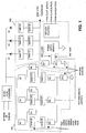
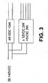
- a 48 VDC DC-DC converter is provided with, for example, an input voltage of 36-140 volts DC.
- other input and output voltages to and from the DC converter are also possible.
- 50-90 volts DC could also be provided as the input voltage to the 48 DC-DC converter.
- the output of the 48 VDC DC-DC converter in FIG. 1 is provided to two power monitoring circuit sections that guarantee the vitality of the power supply.
- the two power monitoring circuits are represented as PM1 and PM2 as shown in FIG. 1 and each provides a reference voltage to a power supply monitor device, which is included as part of the control system of the vital power supply system.
- the power supply monitor provides over-voltage and under-voltage protection, based on the outputs of the power monitoring circuits.
- the "Power Good” output of the power supply monitor is asserted low and the fault is latched. If the fault condition clears up, the latch controlling the "Power Good” circuit in the power supply monitor is cleared once the condition is detected and debounced.
- An "out-of-tolerance" condition causes the power supply monitor to switch a logic level of the "Power Good” signal to a level that indicates the power is not good which, for example, turns ON an LED indicator mounted on the front panel of.the VPS, indicating a problem.
- the "Power Good” signal is optically isolated, replicated and transmitted to the Peripheral Interface Communications Control (PICC) modules in the Peripheral Processing Unit (MPU) (not shown).
- PICC Peripheral Interface Communications Control
- MPU Peripheral Processing Unit
- the PICC and PPU are subsystems that are necessary for controlling both driverless and driver operated trains.
- a PICC which is part of the control system of the vital power supply, is a DSP based 3U-Euro card that controls the peripheral equipment attached to the train, monitors status, speed sensors, accelerometers, provides safety features and vital check back signals necessary for Automatic Train Control System Applications.
- the PPU is the interface that directly connects to the train control circuits and train line to monitor and collect the status of the control signals, speed of train, conditions of the train power supplies and propulsion systems etc.
- Power monitoring circuit PM2 is referred to herein as the output voltage tolerance test circuit since it monitors the output voltage of the 48 VDC supply
- circuit PM1 is referred to as the input voltage tolerance test circuit since its main function is to monitor the voltage being input to the output voltage test circuit, determine if the voltage is adequate, and modify the tolerance of the determination.
- the tolerance levels associated with circuit PM1 are controllably adjusted such that various voltage specifications can be accommodated.
- circuits PM1 and PM2 shown in FIG. 1 A description of circuits PM1 and PM2 shown in FIG. 1 will now be provided.
- circuit PM2 i.e., the output voltage test circuit
- PhotoMOS switches, S1-S6, shown on the top, right-hand side of FIG. 1 are selectively enabled by three Peripheral Interface Communications Control (PICC) modules (not shown), as discussed below.
- the three PICC modules each receive a respective copy of the "Power Good” signal, i.e., Power Good #1, #2 and #3, the logic state of which indicates whether or not an adequate 48 VDC voltage is being delivered from the 48 VDC converter and whether an adequate voltage is being provided to the load, e.g., the RATP Transponder in the present embodiment.
- the PICCs which include respective DSPs, receive their respective replicas of the "Power Good” signal and generate enable signals based on the logic state of the "Power Good” signal.
- the PICCs determine the control state of the enable signals based on a programmed algorithm and the values of the "Power Good” signal and various other inputs as required.
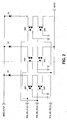
- the enable signals thus generated are provided to the various switches of PM1 and PM2, the details of which are shown in FIG. 2 . Use and effect of the enable signals as they pertain to the respective switches of PM1 and PM2 is described below.
- a reference voltage is derived that indicates the value of the voltage being supplied to the load, e.g., the 48VDC provided to the transponder. More particularly, as shown on the right-hand side of FIG. 1 , pairs of switches (S1, S2) and or (S3, S4) and or (S5, S6) or all three pairs enable the 48VDC power to be supplied to the load.
- FIG. 2 illustrates a detailed representation of the switches provided in PM2. That is, in regard to PM2, switches SW1-SW6 in FIG. 2 represent switches S1-S6 of FIG. 1 , respectively.
- the output of the 48VDC converter is provided respectively, to the three switch circuits comprising S1-S2, S3-S4 and S5-S6, respectively.
- resistors R11 and R12 are precision resistors and comprise a voltage divider which is used to provide a sample reference voltage, for example, 3.3VDC, which is derived from the output of the 48VDC power source after the switches S1-S6.
- the sample reference voltage is provided to the power supply monitor IC which determines, based on the value of the reference signal, what the logic state of the "Power Good" signal will be.
- Each of the PICCs receives a replica of the "Power Good" logic signal and after performing their respective processing in respective DSPs, provides respective enable signals ENA_48_PICC1, ENA_48_PICC2 and ENA_488_PICC3, as shown in FIG. 2 , to controllable enable the switches.
- each of switches SW1-SW6 is controllably enabled by a particular enable signal.
- SW1 and SW2 are controlled by enable signal ENA_48V_PICC1, which comes from PICC1;
- SW3 and SW4 are controlled by enable signal ENA_48V_PICC2, which comes from PICC2;
- SW5 and SW6 are controlled by enable signal ENA_48V_PICC3, which comes from PICC3.
- the 48VDC input voltage shown at the top of FIG. 2 is selectively provided through the switch pairs at the bottom of FIG. 2 based on the relative positions of switches SW1-SW6. If all switches SW1-SW6 are enabled, the input voltage is provided through all three switch pairs. However, if, for example, SW1 is not enabled, (because PICC1 has not generated a valid enable signal, ENA_48V_PICC1) switches SW1 and SW2 will not be enabled, thus, both switch pairs SW1/SW4 and SW2/SW5 will be unable to provide the input voltage as shown near the bottom of FIG. 2 . Under these conditions, the only path through which the input voltage can be provided to the output is through switch pair SW3/SW6.
- PICC2 fails to provide an enable signal, i.e., ENA_48V_PICC2
- switches SW3 and SW4 will be disabled and the only path through which the input voltage can be provided to the output is through switch pair SW2/SW5.
- the reference voltage e.g., 3.3 VDC
- the reference voltage is generated at the input to the power supply monitor only if at least two of the three PICCs generate their respective enable signals for the switches. That is, if two or more of the PICCs fail to generate their respective enable signal, there will be no path through which the 48VDC output of the DC-DC .converter can traverse to provide an input to the voltage divider comprising R11 and R12, to generate the reference voltage.
- the reference voltage is 3.3 VDC, based on the respective values of R11 and R12 and the 48 VDC output voltage of the DC-DC converter.
- the 3.3 VDC reference can be obtained by selecting appropriate ratio of resistor values for R11 and R12 that depends on the output voltage desired to meet the particular application.
- the power monitoring circuit PM2 if the output of the 48VDC power source is either above or below a rated tolerance, as determined by the power supply monitor based on the value of the reference voltage generated by voltage divider R11 and R12, the power supply monitor will generate an over voltage or under-voltage condition, respectively, and control the logic state of the "Power Good” signal, accordingly.
- the "Power Good” signal is replicated and sent to each of the respective PICCs which in turn, inform their respective main processors (MPU).
- the main processors include, for example, Pentium II or III class based 3U-Euro-cards that function under the TAS Operating System Software designed for train control applications.
- the PICC modules inform MPU counterparts via CAN (Controller Area Network) individually. For example, as mentioned above, the status of the power supply is provided to the MPU and, if necessary, the MPU cause a corrective action based on the fault management system implemented for the intended application.
- the fault management system is a unique piece of software that is application specific.
- a fault management system implemented for this application is designed to resolve problems by degrading the system in a controlled and safe way.
- the fault management system will, for example, inform the train driver there is a serious issue that has to be resolved. Further, at the next train stop the propulsion systems will be disabled so the train cannot be move until the problem is resolved at the station.
- the fault management system in a driverless train would inform the subway system operators that there is a problem with a specific train on a specific line, the location, speed, direction of travel and the nearest station stop possible. The level of sophistication and the extent of control is strictly a matter of choice selected by the application.
- switches S8-S13 of PM1 are each configured identically to the switch configuration shown in FIG. 2 . That is, unlike the switches in PM1 where each switch S1-S8 corresponded to SW1-SW8 of FIG. 2 , respectively, the switches in PM1 each comprise all six switches SW1-SW6 of FIG. 2 . A more detailed description of the operation of switches S8-S13 is provided below.
- the switches, S8-S13, in PM1 are each configured similar to the six switches illustrated in FIG. 2 and they each operate as follows.
- each switch, S8-S13 is controllably enabled by three enable signals generated by the three respective PICCs.
- each of the switches is controlled by ENA_48V_PICC1, ENA_48V_PICC2 and ENA_48V_PICC3. Accordingly, various switch conditions can be achieved by selectively enabling switches S8-S13.
- a 5 volt reference voltage is increased or decreased based on whether or not certain switches, S8-S13, are enabled and whether resistors R2, R5 and R8 are placed within the respective current paths.
- the equivalent resistance of the resistor network of PM1 changes and, thus, the equivalent potential at the junction of R9 and R10 changes. If the voltage at the junction of R9 and R10 drops below the preferred 5VDC level, an under-voltage condition is determined in the power supply monitor and the Power Good" signal output from the power supply monitor indicates that power is not good.
- the replication circuit takes the "Power Good” logic signal from the power supply monitor and passes it through the three independent opto-isolator circuits producing three identical replicas of the "Power Good” signal, each galvanically isolated from the others, and supplies them to the three respective PICC modules.
- resistors R2, R5 and R8, respectively are bypassed and R1 in series with R3, R4 in series with R6, and/or R7 in series with R9, provide three parallel current paths.
- the equivalent resistance of the PM1 circuit is then reduced to two thirds or one third the value of R9, depending on which switches are enabled and which ones are disabled. Further, lowering the equivalent value of the resistor network causes the potential at the junction of R9 and R10 to increase above a 5VDC reference level, which causes an out of tolerance condition, i.e., "over-voltage", at the 5V input to the power supply monitor illustrated as part of PM2.
- the PICCs provide their respective processors with their copy of the "Power Good" logic signal and the processors determine which switches to enable and which ones to disable, i.e., by providing the appropriate level on the respective enable signals associated with the switches.
- switch S8 would be disabled by providing the necessary signal level on at least two of the three enable signals that control S8. As understood from FIG. 2 , it takes at least two of the three enable signals to be in the same logic state to control the switch one way or another. That is, if only PICC1 were to attempt to disable, i.e., open, a particular switch, the path through SW3/SW6 would still be closed.
- Each of the switches S8-S13 operates in similar fashion. That is, if two or three of the enable signals from the respective PICCs attempt to open or close a switch, the switch can be controlled, accordingly. However, if less than two of the PICCs are in agreement and, thus, and less than two enable signals attempt to control the switch, the desired function can not be performed. Accordingly, based on the respective logic levels of the enable signals, ENA_4 8V_PICC1, ENA_48V_PICC2 and ENA_4 8V_PICC3, different resistor network configurations can be achieved in PM1 by switching in, or out, resistor R2, R5 and R8, accordingly.
- a vital power supply comprises commercial-off-the-shelf (COTS) power supplies and utilizes DC-DC converters qualified to CENELEC requirements.
- COTS commercial-off-the-shelf
- DC-DC converters qualified to CENELEC requirements.
- available COTS ⁇ 12VDC, 48VDC and 5VDC DC-DC converters are placed on a single Euro card, such as a 3U or 6U card. Since the converters are small enough, the monitoring circuits, as described above, and replication of the "Power Good" output and power shut-down circuits fit on the same Euro card as the converters.
- the power monitoring circuits, power supply monitor and replicating circuits in the second embodiment are the same as those discussed above in regard to the first embodiment and, thus, further detailed description of these circuits is not provided.
- a favorable "Power Good” logic signal is generated, for example, by the power supply monitor if there are no over-voltage or under-voltage conditions with the three supplies, i.e., the 5 VDC, + 12VDC and -12 VDC outputs, that it monitors. Should a fault condition occur on any one of the three output voltages the power supply monitor causes the "Power Good" logic signal output to indicate that power is not good.
- the replicating opto-isolator circuits convert this single output signal into three optically isolated signals that are made available to the three PICC modules that a fault has occurred.
- power shut down circuits are also provided.
- the two PhotoMOS drivers energized, for example, by signals ENA_48_PICC1 and ENA_4 8_PICC2 are required for the +48VDC output voltage to be made available to an external load (not shown).
- the three PICC modules have to "vote” by enabling the voltage paths through three diodes (shown on the top right hand side of FIG. 1 ) for the power to be available. Should a fault condition occur with the vital power supply; the power supply monitor asserts an inverted "Power Good" signal indicating that the power is not good.
- the signal is replicated by the opto-isolator circuits and communicated to the PICC modules.
- the PICCs provide the "Power Good" signal to their respective processors and it is determined which switches will be enabled and which ones will be disabled. Accordingly, it takes at least two of the three PICCs to shut-down power. For instance, as described above, if only PICC1 were to vote to shut down power, thus, sending an appropriate level on its enable signal, and each of PICC2 and PICC3 send opposite enable signals, the power will not be shut down.
- Advantages provided by the second embodiment include using COTS components that are already COTS qualified; the addition of monitoring, replicating and shutdown functional circuits are much easier; wide input voltage, e.g., 36-140VDC, are provided to accommodate, for example, the 55-90 VDC required by systems such as RATP. Additional benefits are that the present embodiment is cost efficient and the VPS system fits on a 3U Eurocard. Lastly, the present embodiment allows a wide range of DC-DC products from multiple sources to be used.
Landscapes
- Engineering & Computer Science (AREA)
- Power Engineering (AREA)
- Business, Economics & Management (AREA)
- Emergency Management (AREA)
- Power Sources (AREA)
- Measurement And Recording Of Electrical Phenomena And Electrical Characteristics Of The Living Body (AREA)
Claims (10)
- Stromversorgungssystem zum Versorgen einer Last mit Strom, wobei das System aufweist:einen Spannungswandler zum Erzeugen einer gewünschten Spannung;erste und zweite Vitalitätsüberwachungsschaltungen zum Überwachen der von dem Spannungswandler erzeugen Spannung und zum Erzeugen jeweiliger Referenzspannungen;ein Steuersystem umfassend zwei oder mehr Verarbeitungseinheiten, die funktionsfähig mit den Vitalitätsüberwachungsschaltungen verbunden sind, wobei das Steuersystem so betreibbar ist, dass es eine Vitalität des Wandlers auf der Basis von Referenzspannungen von den Vitalitätsüberwachungsschaltungen bestimmt und weiterhin so betreibbar ist, dass es den der Last zugeführten Strom auf der Basis einer Bestimmung, den Strom von mindestens zwei der Verarbeitungseinheiten abzuschalten, abschaltet,dadurch gekennzeichnet, dassdie erste Vitalitätsüberwachungsschaltung zwei oder mehr Schaltungszweige aufweist, wobei jeder Zweig einen oder mehr Schalter aufweist, die jeweils eine offene und eine geschlossene Stellung und einen oder mehr Widerstände haben, dass weiterhin die jeweilige Referenzspannung von der ersten Vitalitätsüberwachungsschaltung durch die Schalterstellungen gesteuert wird, unddass alle Schalter der ersten Vitalitätsüberwachungsschaltung identisch sind und die Stellungen der Schalter durch jeweilige Eingaben von mindestens zwei der Verarbeitungseinheiten gesteuert werden.
- Stromversorgungssystem nach Anspruch 1, wobei das Steuersystem weiterhin eine Stromversorgungsüberwachung aufweist, die so betreibbar ist, dass sie die jeweiligen Referenzspannungen von der ersten und zweiten Vitalitätsüberwachungsschaltung empfängt.
- Stromversorgungssystem nach Anspruch 1, wobei die Widerstände der ersten Vitalitätsüberwachungsschaltung einen Spannungsteiler bilden zum Steuern des Spannungspegels der Referenzspannung der ersten Vitalitätsüberwachungsschaltung und wobei der Wert des Spannungsteilers auf der Basis der Schalterstellungen bestimmt wird.
- Stromversorgungssystem nach Anspruch 1, wobei die zweite Vitalitätsüberwachungsschaltung zwei oder mehr Schaltungszweige aufweist, wobei jeder Zweig zwei oder mehr Schalter aufweist, die jeweils eine offene und eine geschlossene Stellung haben.
- Stromversorgungssystem nach Anspruch 4, wobei die Schalter alle von einer jeweiligen Verarbeitungseinheit gesteuert werden.
- Stromversorgungssystem nach Anspruch 4, wobei jeder Schaltungszweig ein jeweiliges Schalterpaar aufweist und jedes Schalterpaar von zwei unterschiedlichen der Verarbeitungseinheiten gesteuert wird.
- Stromversorgungssystem nach Anspruch 2, wobei die Stromversorgungsüberwachung ein Power-Good Signal erzeugt, das anzeigt, ob der Strom von dem Wandler gut ist und wobei das Power-Good Signal auf den jeweiligen Referenzspannungen von der ersten und zweiten Vitalitätsüberwachungsschaltung basiert.
- Stromversorgungssystem nach Anspruch 7, weiterhin umfassend eine Replikationsschaltung, die so betreibbar ist, dass sie das Power-Good Signal von der Stromversorgungsüberwachung empfängt und mehrere galvanisch isolierte Kopien für jede der jeweiligen Verarbeitungseinheiten erzeugt.
- Stromversorgungssystem nach Anspruch 1, wobei der Wandler mindestens vier Ausgangsspannungen hat;
wobei eine erste und eine zweite der Vitalitätsüberwachungsschaltungen jeweils den Ausgangsspannungen zum Überwachen jeder Ausgangsspannung entsprechen;
wobei das Steuersystem zwei oder mehr Verarbeitungseinheiten aufweist, die funktionsfähig mit den Vitalitätsüberwachungsschaltungen verbunden sind, wobei das Steuersystem betreibbar ist, um eine Vitalität jeder der Ausgangsspannungen des Wandlers auf der Basis von Referenzspannungen von den Vitalitätsüberwachungsschaltungen zu bestimmen und weiterhin betreibbar ist, um eine oder mehr der Ausgangsspannungen auf der Basis einer Bestimmung, die Spannung von mindestens zwei der Verarbeitungseinheiten abzuschalten, abzuschalten. - Stromversorgungsanordnung zum Versorgen einer Last mit Strom, umfassend:mindestens zwei Stromversorgungssysteme nach Anspruch 1.
Applications Claiming Priority (4)
| Application Number | Priority Date | Filing Date | Title |
|---|---|---|---|
| US49859503P | 2003-08-29 | 2003-08-29 | |
| US498595P | 2003-08-29 | ||
| US920414 | 2004-08-18 | ||
| US10/920,414 US20050046440A1 (en) | 2003-08-29 | 2004-08-18 | Fault tolerant vital power supply system |
Publications (3)
| Publication Number | Publication Date |
|---|---|
| EP1511167A2 EP1511167A2 (de) | 2005-03-02 |
| EP1511167A3 EP1511167A3 (de) | 2008-07-23 |
| EP1511167B1 true EP1511167B1 (de) | 2016-02-17 |
Family
ID=34108121
Family Applications (1)
| Application Number | Title | Priority Date | Filing Date |
|---|---|---|---|
| EP04020257.4A Expired - Lifetime EP1511167B1 (de) | 2003-08-29 | 2004-08-26 | Fehlertolerantes Stromversorgungssystem |
Country Status (2)
| Country | Link |
|---|---|
| US (1) | US20050046440A1 (de) |
| EP (1) | EP1511167B1 (de) |
Families Citing this family (7)
| Publication number | Priority date | Publication date | Assignee | Title |
|---|---|---|---|---|
| US7466894B2 (en) * | 2005-05-23 | 2008-12-16 | Semiconductor Components Industries, L.L.C. | Power supply output monitor |
| US7590890B2 (en) * | 2006-08-23 | 2009-09-15 | Micrel, Inc. | Hot-swap power controller generating sequenced power-good signals |
| CN101369008B (zh) * | 2007-08-17 | 2010-12-08 | 鸿富锦精密工业(深圳)有限公司 | 冗余电源供应器的热切换测试系统及方法 |
| CN106300944B (zh) * | 2016-08-06 | 2018-12-14 | 杰华特微电子(张家港)有限公司 | 过流控制电路、过流控制方法及应用其的电源系统 |
| US11031804B2 (en) * | 2017-11-06 | 2021-06-08 | Nxp B.V. | Power controller |
| CN109783282B (zh) * | 2017-11-15 | 2022-06-28 | 纬联电子科技(中山)有限公司 | 计算机装置以及电源异常检测方法 |
| CN111830858B (zh) * | 2019-04-23 | 2025-09-16 | 联合汽车电子有限公司 | 电子控制系统 |
Family Cites Families (26)
| Publication number | Priority date | Publication date | Assignee | Title |
|---|---|---|---|---|
| JPS54137649A (en) * | 1978-04-18 | 1979-10-25 | Tokyo Electric Power Co Inc:The | Digital protective relay device |
| US4438498A (en) * | 1981-07-13 | 1984-03-20 | Tektronix, Inc. | Power supply output monitoring method and apparatus |
| US4967347A (en) * | 1986-04-03 | 1990-10-30 | Bh-F (Triplex) Inc. | Multiple-redundant fault detection system and related method for its use |
| JPH0771381B2 (ja) * | 1991-08-09 | 1995-07-31 | 株式会社ピーエフユー | 電源供給系評価装置 |
| US5525913A (en) * | 1994-10-19 | 1996-06-11 | Intel Corporation | Power validation tool for microprocessor systems |
| US5613064A (en) * | 1995-01-13 | 1997-03-18 | Curtin; Keith W. | Output network for a fault tolerant control system |
| US5866956A (en) * | 1995-06-06 | 1999-02-02 | Dekko Engineering, Inc. | Apparatus for and method of monitoring and controlling a power system |
| US5610532A (en) * | 1995-07-31 | 1997-03-11 | Magl Power Inc. | Isolated DC fault current sensor |
| US5710701A (en) * | 1995-07-31 | 1998-01-20 | Deli Usa, L.P. | Method and apparatus for power supply testing |
| US5789934A (en) * | 1996-05-23 | 1998-08-04 | Hewlett-Packard Company | Test circuit including a power supply with a current transformer to monitor capacitor output current |
| JP3390824B2 (ja) * | 1997-03-19 | 2003-03-31 | 株式会社日立製作所 | 多重化制御装置及びその障害回復方法 |
| JPH10288634A (ja) * | 1997-04-16 | 1998-10-27 | Nec Ic Microcomput Syst Ltd | 電源電圧検出回路 |
| JP3045763U (ja) * | 1997-07-30 | 1998-02-13 | 船井電機株式会社 | 電源電圧の異常状態表示装置 |
| JPH1164041A (ja) * | 1997-08-12 | 1999-03-05 | Mitsubishi Electric Corp | 物理量センサ |
| JP3063708B2 (ja) * | 1997-11-05 | 2000-07-12 | 日本電気株式会社 | 無停止電源システム並びにこれに用いる被バックアップ装置及びコンピュータを被バックアップ装置として動作させるためのプログラムを記録した記録媒体 |
| US6456106B1 (en) * | 1997-12-08 | 2002-09-24 | Srmos, Inc. | Method and circuit for detection of primary switches status in isolated DC/DC converters |
| US6198302B1 (en) * | 1998-04-02 | 2001-03-06 | Lucent Technologies Inc. | System and method for testing power supplies |
| JP3482873B2 (ja) * | 1998-05-20 | 2004-01-06 | 株式会社デンソー | 負荷駆動装置 |
| TW381212B (en) * | 1998-06-16 | 2000-02-01 | Asustek Comp Inc | Detector for standby power supply capacity |
| US6181029B1 (en) * | 1998-11-06 | 2001-01-30 | International Business Machines Corporation | Method of controlling battery back-up for multiple power supplies |
| JP3866436B2 (ja) * | 1999-03-18 | 2007-01-10 | 株式会社東芝 | 半導体装置及びこれを備えた半導体システム |
| JP2000324804A (ja) * | 1999-04-28 | 2000-11-24 | Ando Electric Co Ltd | 電源供給システムの不良電源検出方法及び装置 |
| CA2277686A1 (en) * | 1999-07-14 | 2001-01-14 | Milltronics Ltd. | An intrinsically safe universal switching power supply |
| CA2439128C (en) * | 2001-02-26 | 2012-02-14 | Legic Identsystems Ag | Method for operating non-contact identification media |
| US6504395B1 (en) * | 2001-08-30 | 2003-01-07 | Teradyne, Inc. | Method and apparatus for calibration and validation of high performance DUT power supplies |
| US6778122B2 (en) * | 2002-12-23 | 2004-08-17 | Institute Of Microelectronics | Resistor string digital to analog converter with differential outputs and reduced switch count |
-
2004
- 2004-08-18 US US10/920,414 patent/US20050046440A1/en not_active Abandoned
- 2004-08-26 EP EP04020257.4A patent/EP1511167B1/de not_active Expired - Lifetime
Also Published As
| Publication number | Publication date |
|---|---|
| US20050046440A1 (en) | 2005-03-03 |
| EP1511167A3 (de) | 2008-07-23 |
| EP1511167A2 (de) | 2005-03-02 |
Similar Documents
| Publication | Publication Date | Title |
|---|---|---|
| EP0215348B1 (de) | Redundantes Stromversorgungssystem | |
| US4400792A (en) | Dual-channel data processing system for railroad safety purposes | |
| US6121693A (en) | Distributed power system | |
| US6385562B1 (en) | Method and apparatus for monitoring a plant with several functional units | |
| EP1511167B1 (de) | Fehlertolerantes Stromversorgungssystem | |
| US6150736A (en) | Redundant electrical power source, distribution and consumption system | |
| US7112896B2 (en) | Power system with load matrix | |
| RU2419123C1 (ru) | Управляющий вычислительный комплекс маневровой автоматической локомотивной сигнализации | |
| RU174331U1 (ru) | Шкаф устройства интервального регулирования движения поездов на перегоне системы | |
| DE3223779A1 (de) | Fehlersichere adersparende lichtsignalsteuereinrichtung | |
| RU2388636C2 (ru) | Микропроцессорная система автоблокировки | |
| RU172264U1 (ru) | Мобильный восстановительный комплекс электрической централизации | |
| Sansyzbay et al. | Development of an algorithm for a national microprocessor-based centralization system with a modular architecture KZ-MPC-MA featuring advanced intelligent control functions | |
| US6777830B1 (en) | System for reliable prevention of the restarting of a machine | |
| Spunei et al. | Automatic block signaling installation failure diagnosis with LCOBla | |
| EP1175719B1 (de) | Anordnung zur zuverlässigen vermeidung vom wiederanfahren einer maschine | |
| RU2790210C1 (ru) | Модульный восстановительный пункт регулирования движения поездов | |
| De Beck et al. | The Programmable Railway Signalling Interlocking | |
| CN101082653B (zh) | 飞行器功率故障仿真设备和方法 | |
| EP4101680A1 (de) | Energieverteilungssystem, steuerungssystem, eisenbahntransportsystem und verfahren zum betreiben eines energieverteilungssystems | |
| RU2847828C1 (ru) | Двухканальная отказоустойчивая система для контроля состояния и управления объектами станции и прилегающих перегонов | |
| Bagnasco et al. | Requirements and Design for a Distributed Computerized System for Safety and Control Applications | |
| JPH10338134A (ja) | 列車の信号保安制御装置 | |
| Sonneck et al. | Assessment and Certification of Safety-Critical Digital Architectures—the ACRuDA Project | |
| Ford | The Static Transfer Switch |
Legal Events
| Date | Code | Title | Description |
|---|---|---|---|
| PUAI | Public reference made under article 153(3) epc to a published international application that has entered the european phase |
Free format text: ORIGINAL CODE: 0009012 |
|
| AK | Designated contracting states |
Kind code of ref document: A2 Designated state(s): AT BE BG CH CY CZ DE DK EE ES FI FR GB GR HU IE IT LI LU MC NL PL PT RO SE SI SK TR |
|
| AX | Request for extension of the european patent |
Extension state: AL HR LT LV MK |
|
| RAP1 | Party data changed (applicant data changed or rights of an application transferred) |
Owner name: ALCATEL LUCENT |
|
| PUAL | Search report despatched |
Free format text: ORIGINAL CODE: 0009013 |
|
| AK | Designated contracting states |
Kind code of ref document: A3 Designated state(s): AT BE BG CH CY CZ DE DK EE ES FI FR GB GR HU IE IT LI LU MC NL PL PT RO SE SI SK TR |
|
| AX | Request for extension of the european patent |
Extension state: AL HR LT LV MK |
|
| 17P | Request for examination filed |
Effective date: 20080814 |
|
| 17Q | First examination report despatched |
Effective date: 20090112 |
|
| AKX | Designation fees paid |
Designated state(s): DE FR GB IT |
|
| RAP1 | Party data changed (applicant data changed or rights of an application transferred) |
Owner name: ALCATEL LUCENT |
|
| RAP1 | Party data changed (applicant data changed or rights of an application transferred) |
Owner name: ALCATEL LUCENT |
|
| REG | Reference to a national code |
Ref country code: DE Ref legal event code: R079 Ref document number: 602004048633 Country of ref document: DE Free format text: PREVIOUS MAIN CLASS: H02M0007480000 Ipc: H02M0003158000 |
|
| GRAP | Despatch of communication of intention to grant a patent |
Free format text: ORIGINAL CODE: EPIDOSNIGR1 |
|
| RIC1 | Information provided on ipc code assigned before grant |
Ipc: H02M 3/158 20060101AFI20150529BHEP Ipc: H02J 9/06 20060101ALI20150529BHEP Ipc: H02M 1/32 20070101ALN20150529BHEP |
|
| INTG | Intention to grant announced |
Effective date: 20150618 |
|
| GRAS | Grant fee paid |
Free format text: ORIGINAL CODE: EPIDOSNIGR3 |
|
| GRAA | (expected) grant |
Free format text: ORIGINAL CODE: 0009210 |
|
| RAP1 | Party data changed (applicant data changed or rights of an application transferred) |
Owner name: THALES S.A. |
|
| AK | Designated contracting states |
Kind code of ref document: B1 Designated state(s): DE FR GB IT |
|
| REG | Reference to a national code |
Ref country code: GB Ref legal event code: FG4D |
|
| REG | Reference to a national code |
Ref country code: DE Ref legal event code: R096 Ref document number: 602004048633 Country of ref document: DE |
|
| REG | Reference to a national code |
Ref country code: FR Ref legal event code: PLFP Year of fee payment: 13 |
|
| REG | Reference to a national code |
Ref country code: DE Ref legal event code: R097 Ref document number: 602004048633 Country of ref document: DE |
|
| PLBE | No opposition filed within time limit |
Free format text: ORIGINAL CODE: 0009261 |
|
| STAA | Information on the status of an ep patent application or granted ep patent |
Free format text: STATUS: NO OPPOSITION FILED WITHIN TIME LIMIT |
|
| 26N | No opposition filed |
Effective date: 20161118 |
|
| REG | Reference to a national code |
Ref country code: FR Ref legal event code: PLFP Year of fee payment: 14 |
|
| REG | Reference to a national code |
Ref country code: FR Ref legal event code: PLFP Year of fee payment: 15 |
|
| PGFP | Annual fee paid to national office [announced via postgrant information from national office to epo] |
Ref country code: IT Payment date: 20220712 Year of fee payment: 19 Ref country code: GB Payment date: 20220714 Year of fee payment: 19 Ref country code: DE Payment date: 20220712 Year of fee payment: 19 |
|
| PGFP | Annual fee paid to national office [announced via postgrant information from national office to epo] |
Ref country code: FR Payment date: 20220721 Year of fee payment: 19 |
|
| REG | Reference to a national code |
Ref country code: DE Ref legal event code: R119 Ref document number: 602004048633 Country of ref document: DE |
|
| GBPC | Gb: european patent ceased through non-payment of renewal fee |
Effective date: 20230826 |
|
| PG25 | Lapsed in a contracting state [announced via postgrant information from national office to epo] |
Ref country code: GB Free format text: LAPSE BECAUSE OF NON-PAYMENT OF DUE FEES Effective date: 20230826 |
|
| PG25 | Lapsed in a contracting state [announced via postgrant information from national office to epo] |
Ref country code: IT Free format text: LAPSE BECAUSE OF NON-PAYMENT OF DUE FEES Effective date: 20230826 Ref country code: GB Free format text: LAPSE BECAUSE OF NON-PAYMENT OF DUE FEES Effective date: 20230826 Ref country code: FR Free format text: LAPSE BECAUSE OF NON-PAYMENT OF DUE FEES Effective date: 20230831 Ref country code: DE Free format text: LAPSE BECAUSE OF NON-PAYMENT OF DUE FEES Effective date: 20240301 |