EP1511048B1 - Redundanter Schalter mit Torsionsnachgiebigkeit und Lichtbogenlöschmasse - Google Patents
Redundanter Schalter mit Torsionsnachgiebigkeit und Lichtbogenlöschmasse Download PDFInfo
- Publication number
- EP1511048B1 EP1511048B1 EP04012894A EP04012894A EP1511048B1 EP 1511048 B1 EP1511048 B1 EP 1511048B1 EP 04012894 A EP04012894 A EP 04012894A EP 04012894 A EP04012894 A EP 04012894A EP 1511048 B1 EP1511048 B1 EP 1511048B1
- Authority
- EP
- European Patent Office
- Prior art keywords
- spanner
- switch
- recited
- nubs
- contact block
- Prior art date
- Legal status (The legal status is an assumption and is not a legal conclusion. Google has not performed a legal analysis and makes no representation as to the accuracy of the status listed.)
- Expired - Fee Related
Links
Images


Classifications
-
- H—ELECTRICITY
- H01—ELECTRIC ELEMENTS
- H01H—ELECTRIC SWITCHES; RELAYS; SELECTORS; EMERGENCY PROTECTIVE DEVICES
- H01H1/00—Contacts
- H01H1/12—Contacts characterised by the manner in which co-operating contacts engage
- H01H1/14—Contacts characterised by the manner in which co-operating contacts engage by abutting
- H01H1/20—Bridging contacts
-
- H—ELECTRICITY
- H01—ELECTRIC ELEMENTS
- H01H—ELECTRIC SWITCHES; RELAYS; SELECTORS; EMERGENCY PROTECTIVE DEVICES
- H01H13/00—Switches having rectilinearly-movable operating part or parts adapted for pushing or pulling in one direction only, e.g. push-button switch
- H01H13/50—Switches having rectilinearly-movable operating part or parts adapted for pushing or pulling in one direction only, e.g. push-button switch having a single operating member
- H01H13/503—Stacked switches
-
- H—ELECTRICITY
- H01—ELECTRIC ELEMENTS
- H01H—ELECTRIC SWITCHES; RELAYS; SELECTORS; EMERGENCY PROTECTIVE DEVICES
- H01H1/00—Contacts
- H01H2001/0005—Redundant contact pairs in one switch for safety reasons
Definitions
- the invention relates to switch assemblies, and in particular relates to a reliable contact block with a double break spanner.
- Electrical switches such as pushbuttons or rotary switches, and the like, used for the control of industrial equipment, are typically mounted onto a front panel of a cabinet so that the manipulated portion of the switch (termed the "pushbutton operator") projects out from and is accessible at the front of the cabinet.
- a hole of sufficient diameter may be punched in the cabinet to accommodate the threaded portion of the operator
- the threaded portion is inserted through the hole, and secured to the panel with a threaded retaining nut.
- the panel is thus sandwiched between the operator and the retaining nut.
- a latch assembly is mounted on the end of the operator protruding inside the panel and a contact block or a plurality of contact blocks are mounted onto the other side of the latch assembly.
- the contact blocks are electrically connected to the circuit or circuits that the switch is to control.
- Contact blocks typically include housings that contain normally open and/or normally closed contacts.
- a normally open contact may be used, for example, when a user wishes to activate a specified function by actuating the operator, thereby closing the normally open contact.
- a plunger returns to its normal position, thereby opening the normally open contact and terminating the controlled function.
- a normally closed contact may be used when a user wishes to stop an ongoing function.
- a normally closed contact is an Emergency Stop (E-Stop) function which is activated when the user wishes to immediately terminate the controlled function due, e.g., to a malfunction in the process or the development of a situation that may cause damage to the product line or the operating equipment.
- E-Stop Emergency Stop
- the normally closed contact opens and remains open until the operator is returned to its normal state, thereby closing the normally closed contact and resuming the controlled function.
- a conventional switch 20 including a spanner 21 that is disposed above a pair of contact plates 24.
- Spanner 21 is a double break spanner, meaning that both outer ends 22 engage a contact plate 24 such that the circuit is broken if either outer end becomes disengaged from the corresponding contact plate.
- each contact plate is aligned with an outer end 22 of spanner 21.
- Spanner 21 and contact plates 24 are of the type that are installed into a contact block (not shown) in the general orientation illustrated.
- a switch operator of a pushbutton may be depressed (in a normally open switch) to bias spanner 21 downwardly along the direction of Arrow A until the outer ends 22 engage the corresponding contact plates 24 to operate a controlled function.
- a contact 26 is in the form of a conductive nub that protrudes upwardly from each contact plate 24 and towards a corresponding outer end 22 to provide a contact location between the spanner 21 and contact plates 24 when the switch 20 is closed.
- the pushbutton is released to allow the spanner 21 to translate upwardly away from contact plates 24 under a spring force along the direction of Arrow B to disengage the outer ends 22 from the contact plates 24 when operation of the controlled function is to be discontinued. It has been recognized, however, that the accumulation of a nonconductive mass (such as dirt, dust and the like) may become lodged between the contact 26 and outer ends of spanner 22, which prevents current from flowing through the closed switch 20. Electrical conduction between contact plates 24 was thus not reliably established in conventional switch 20.
- switch 28 addresses the potential presence of nonconductive masses that could compromise the reliability of switch 20 illustrated in Fig. 1.
- switch 28 includes a spanner 30 having a slot 32 extending longitudinally partially through each outer end 34 to produce a pair of bifurcated fingers 36a and 36b at each end.
- Each finger 36 is independently vertically flexible with respect to the spanner 30 and therefore provides a redundant contact that engages a flat contact plate 38.
- a contact protrudes downwardly from the lower surface of each finger 36 towards the contact plate 38.
- a switch is provided that is of the type that may be installed in a contact block engaging a pushbutton operator via a latch assembly.
- the switch includes a contact defining a first and second end. The first end is connected to an external device controlled by the switch. A first and second nub extends outwardly from the second end.
- a laterally extending conductive spanner has a body connected to an outer end that is aligned with the first and second nubs of each second end, respectively.
- a circuit is formed when the spanner is electrically connected to the second end.
- the outer ends of the spanner are wider than the central portion so as to render the spanner torsionally compliant.
- Fig. 1 is a perspective view of the spanner portion of a control block constructed in accordance with the conventional techniques
- Fig. 2 is a perspective view of another spanner portion of a control block constructed in accordance with conventional techniques
- Fig. 3 is a side elevation view of a switch assembly constructed in accordance with the preferred embodiment having a portion of the control block cutaway, wherein the control block is in an open position;
- Fig. 4 is a perspective view of the spanner portion of the contact block illustrated in Fig. 3;
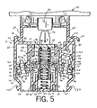
- Fig. 5 is a side elevation view similar to Fig. 3 but with the contact block in a closed position;
- Fig. 6 is a sectional side elevation view of the contact block taken along line 6-6 of Fig. 3;
- Fig. 7 is a sectional side elevation view of the contact block taken along line 7-7 of Fig. 6;
- Fig. 8 is a sectional side elevation view of the contact block taken along line 8-8 of Fig. 6, wherein a nonconductive mass lodged between one of the contact locations;
- Fig. 9 is a sectional side elevation view of a pair of contact blocks vertically stacked to operate in tandem.
- Fig. 10 is a sectional side elevation view of a plurality of contact blocks directly connected to a pushbutton to operate in tandem.
- a contact block 52 is removably connected to a switch operator 54 via a latch assembly 50.
- contact block 52 includes a generally rectangular housing 56 that is connected to a pair of upper flanges 58 that extend upwardly and inwardly from the housing to provide a catch that engages mating flanges 60 extending downwardly from the latch assembly 50.
- Latch assembly 50 includes a rotatable collar 61 that removably engages the cylindrical shaft 62 of a switch operator 54 to the latch assembly 50.
- U.S. Pat. No. 6,376,785 entitled "Removable Latch Assembly for an Electrical Switch".
- a release tab 64 extends outwardly from one of the flanges 58 that is configured to engage the head of a screwdriver, for instance, when it is desired to pull flange 58 out of engagement from flange 60 to disconnect contact block 52 from latch assembly 50.
- Switch operator 54 includes a pushbutton 66 located at a head 68 at one end of cylindrical shaft 62.
- the pushbutton 66 is attached to a stem 70 that extends axially through the shaft 62 to communicate the action of the pushbutton 66 to a plunger 72 in the contact block 52.
- a sheet panel 74 preferably made of sheet metal, has a hold (not shown) that receives the shaft 62, such that pushbutton 66 extends from the outer surface of panel 74, and the contact block 52 extends inwardly from the inner surface of a panel 74.
- External threads 76 are formed on the portion of the shaft 62 passing through the hole in panel 74.
- the head 68 remaining on the outside of the panel 74 when the shaft 62 is inserted into the hole, is drawn against the panel by a retaining nut 78, placed over the shaft inside of the panel, and tightened on the threads 76.
- the panel is thus sandwiched between the nut 78 and an inner face of the head 68.
- pushbutton 66 and latch assembly 50 have been described, it should be noted that any suitable apparatus for connecting the switch operator 54 to a contact block 52 may be used such that actuation of the switch operator in turn actuates the contact block plunger.
- Housing 56 of contact block 52 retains a switch assembly 55 that is in a normally open position.
- Housing 56 includes opposing front and rear walls 80 that are connected at their outer ends to side walls 82. Walls 80 and 82 are connected at their lower ends to a base 83, and are connected at their upper ends to an upper wall 85.
- a pair of contact assemblies 84 is formed at each lateral end of walls 80 and are separated by a centrally disposed axially extending column 86 that comprises a void disposed between walls 80 of adjacent contact assemblies 84.
- axially is used herein synonymously with “vertical” and defines a direction between contact block 52 and pushbutton 66.
- laterally is used herein to define a direction extending perpendicular to side walls 82.
- transverse is used herein to define a direction extending perpendicular to front and rear walls 80.
- Each contact assembly 84 includes a lower retaining wall 88 that extends upwardly from base 83 parallel to side walls 82 at a distance inwardly of side walls 82.
- the upper end 90 of each retaining wall 88 provides a seat for the inner end 92 of an electrically conducting plate 93.
- a pair of corresponding lower guide walls 94 extends upwardly from base 83 a distance less than lower retaining wall 88, and is connected to the adjacent lower retaining wall 88 via a crossbar 96 to ensure structural integrity.
- a pair of upper retaining walls 98 extends downwardly from upper wall 85 parallel to side walls 82 at a distance inwardly of side walls 82.
- the lower end of each upper retaining wall 98 is connected to a mounting wall 100 that extends laterally outwardly to the corresponding side wall 82.
- a pair of corresponding upper guide walls 102 extends downwardly from upper wall 85 a distance less than upper retaining walls 98, and is connected to the adjacent upper retaining wall 98 via a crossbar 104 to ensure structural integrity.
- An angled wall 107 is connected to the interface 106 of mounting wall 100 and one of the side walls 82.
- Wall 107 extends generally upwardly and then generally inwardly and is connected to the upper end of corresponding upper retaining wall 98 to provide structural support for release tab 64.
- the interface 106 provides a hinge that enables the corresponding side wall 82 to flex outwardly in when release tab 64 is engaged.
- Each mounting wall 100 defines an aperture 108 extending through the wall 100 in a direction perpendicular to the wall 100.
- Each electrically conducting plate 93 defines an outer end 110 that extends along the bottom surface of mounting wall 100.
- a cylindrical flange 112 extends generally upwardly from outer end 110 and into aperture 108.
- Flange 112 defines an internally threaded bore.
- Flange 112 receives a screw 114 having a middle threaded portion 116, a lower threaded portion 120 proximal the screw tip, and an upper threaded portion 118 proximal the screw head.
- a V-shaped conducting electrical connector 122 includes first and second walls 124 joined at an apex whose concave surface faces plate 93.
- Apex 124 receives the upper unthreaded portion 118 of screw 114, which has a smaller diameter than the outer diameter of threads 116.
- Flange 112 receives the threaded portion 116, such that the lower unthreaded portion 120 extends beyond flange 112.
- Screw 114 may be rotated clockwise to tighten connector 122 against plate 93, or counterclockwise to translate connector 122 away from plate 93.
- An electrical lead is placed between each connector 122 and plate 93 prior to tightening the respective connector against the plate.
- Connector 122 is sized too large to fit through a gap 125 disposed between the lower end of side wall 82 and lower retaining wall 88. Unthreaded portions 120 and 118 are spaced apart a sufficient distance such that, when screw 114 is rotated counterclockwise until threads 116 become disengaged from flange 112, connector 122 is disposed above gap 125. The mechanical interference between threads 116 and connector 122 coupled with the interference between connector and gap 125 prevents the screw 114 from being completely removed from contact block 52.
- Column 86 is occupied by a housing 130 that carries an electrically conducting laterally extending spanner 126 that, in combination with inner ends 92 of plates 93, provides a normally open switch 133.
- spanner 126 defines lateral outer ends 127 having corresponding lower surfaces 129 that engage the upper surfaces 95 of inner ends 92.
- a pair of domed conductive nubs (electrical contacts) 99 and 101 protrude upwardly from ends 92 and are transversely aligned to provide redundant contact points for spanner 126.
- Nubs 99 and 101 are preferably formed integrally with ends 92.
- Spanner 126 is generally made of copper, however, the lower surfaces 129 of outer ends 127 include a silver coating 131 to increase the electrical contact with nubs 99 and 101. Silver has been found to conduct electricity sufficiently so as to assist in heat dissipation at the outer ends 127 of the spanner, for example when an arc is present. It should be appreciated, however, that spanner 126 could be made of any suitable conductor, and that the outer ends may be coated with any suitable conductor or, alternatively still, the coating 131 may be eliminated. If coating 131 is present, then outer ends 127 have a greater vertical thickness than the remainder of spanner 126. Spanner 126 advantageously is torsionally compliant, as is described in more detail below.
- Plunger 72 extends upwardly from the upper wall 132 of housing 130.
- a pair of opposing side walls 134 have corresponding proximal ends 136 that are connected to the transverse outer edges 138 of wall 132 (See also Fig. 10).
- Side walls 134 extend downwardly from upper wall 132 and terminate at distal ends 140.
- the distal ends 140 retain a plug 142, which may be snap-fit between walls 134.
- Distal ends 140 of walls 134 extend downwardly a slight distance past plug 142, and are separated from each other a distance slightly greater than the transverse thickness of base 83 to enable contact blocks 52 to be vertically stacked, as will be described in more detail below.
- the upper surface 144 of plug 142 provides a seat for spanner 126.
- the lateral outer ends of each wall 134 are flared inwardly towards the opposing wall 134 to define flanges 143.
- Flanges 143 provide a guide for an upper spring 145 that is disposed in housing 130 such that the upper end 146 of spring 145 rests against the lower surface of upper wall 132, and the lower end 148 of spring 145 biases spanner 126 against the upper surface 144 of plug 142.
- a bore 149 extends axially upwardly through the lower surface 146 of plug 142. Bore 149 extends towards, but not all the way to, the upper surface 144.
- Bore 149 is sized to receive the upper end 150 of a lower spring 152 whose lower end 154 is in contact with base 83 of contact block housing 56. Lower spring 152 thus biases housing 130 upwardly such that plunger 72 engages the lower end of stem 70 and spanner 126 is disengaged from plates 93 when contact block 52 and operator 54 are initially installed in latch 50.
- Spanner 126 which is carried by the housing 130, is thus also biased downwardly until outer ends 127 engage the inner ends 92 of plates 93.
- upper spring 145 provides compliance such that housing 130 may continue to be biased downwardly against the force of upper spring 145, which compresses after spanner 126 engages plates 93.
- Spring 145 thus provides a force that biases spanner 126 against plates 93.
- the biasing force of spring 145 increases as housing 126 is increasingly depressed. The downward movement of housing 126 is limited by the stroke length of pushbutton 66, or by interference between the lower surface 146 of plug 142 and base 83.
- switch 133 is configured to provide a redundant electrical contact, and furthermore to resist failure due to arcing at the interface between outer ends 127 and plates 93, as experienced in conventional switch assemblies.
- spanner 126 includes a central laterally extending beam 156 that defines opposing lateral outer ends 127. Each lateral end 127 has opposing transverse outer ends 135 and 123 that are vertically aligned with nubs 99 and 101, respectively.
- a pair of protrusions 158 extends transversely outwardly from a middle portion 160 of beam 156 to a location proximal walls 134. Protrusions 158 extend laterally between flanges so as to stabilize the position of spanner 126 and furthermore to provide guides for axial spanner translation in housing 130.
- Beam 156 has a width (transverse thickness) at locations 162 between protrusions 158 and outer ends 127 that is less than the width of ends 127. Ends 127 are thus T-shaped with respect to the beam sections 162. Ends 127 extend further transversely outwardly than protrusions 158 such that the entire beam 156 has a reduced width with respect to outer ends 127.
- a nonconductive mass 161 such as a piece of dirt, lint, and the like, may become lodged between one of the nubs 99 and transverse outer end 135. Accordingly, electrical contact is unattainable between spanner 126 and nub 99.
- the mass 161 would cause the adjacent transverse outer end 123 to a raised position above, and out of contact with, corresponding nub 101. In such devices, the switch would be unable to close, and control of the external device would be lost.
- the portions 162 of spanner 126 have reduced transverse thicknesses relative to the corresponding lateral outer ends 127.
- spanner 126 is made of a compliant material and has a reduced axial thickness (within the range of.25 mm). Accordingly, when one transverse outer end 135 is raised with respect to corresponding nub 99, the force of upper spring 145 acting on the middle portion 160 of spanner 126 is translated to the other transverse outer end 123 so as to bias end 123 against the corresponding nub 101. Redundant contacts are thus established at each lateral outer end 127 between transverse outer ends 135 and 123, and nubs 99 and 101, respectively.
- Nonconductive mass 161 furthermore does not affect the ability of the opposite outer end 127 of spanner 126 to contact corresponding nubs 99 and 101.
- transverse outer ends 123 or 135 When switch 133 is again opened, one of the transverse outer ends 123 or 135 will, if only for a minute period of time, become disengaged from the corresponding nub prior to the other transverse outer end. For instance, outer end 135 may become disengaged from nub 99 prior to outer end 123 becoming disengaged from nub 101. An arc may thus form at the interface between the remaining end 123 and nub 101.
- Transverse outer ends 135 and 123 are not bifurcated, however, meaning that lateral outer end 127 is a solid member that includes both transverse outer ends. Accordingly, even though an arc may be produced at outer end 123 when the switch 133 is opened, the increased thermal mass of lateral outer end 127 enables spanner 126 to absorb the arc while maintaining its structural integrity.
- sections 162 have a reduced width compared to the width of outer ends 127, and further have a reduced width compared to the width of middle portion 160.
- the reduced width of sections 162 is achieved by forming a corresponding pair of notches 163 between outer ends 127 and middle portion 160.
- notches 163 ensure that heat that accumulates at outer ends 127 thus has a reduced path of conductivity via sections 162.
- the middle portion 160 thus does not become heated as rapidly as conventional spanners, thereby further reducing potentially damaging thermal effects on nearby plastic parts.
- each contact block housing 56 includes a pair of lower flanges 164 that flare laterally outwardly from the lower end of side walls 82 (see Fig. 5).
- Contact blocks 52 may be vertically stacked by connecting lower flanges 164 to upper flanges 58.
- Plunger 72 comprises a pair of fingers 73 (See Fig. 10) that are transversely displaced a greater distance than the transverse thickness of base 83.
- the plunger 72 of lower contact block 52B thus fits over the base 83 of upper contact block 52A so as to engage the lower end of walls 134 of upper contact block A.
- the vertically stacked contact blocks 52A and 52B act in tandem in response to actuation of a single pushbutton 66 to control multiple external devices, or multiple functions of a single external device.
- a plurality of contact blocks 52C, 52D, and 52E are mounted onto a single latch assembly 50 in a transverse orientation such that front and rear walls 80 of each contact block abut each other.
- Stem 70 extends transversely so as to engage both fingers 73 of plunger 72 of the middle contact block 52D along with one of the fingers of the outer contact blocks 52C and 52E. Accordingly, when pushbutton 66 is actuated, the plungers 72 of all three contact blocks 52C-52E are depressed.
- Pushbuttons 52A-52E may individually be normally open as described above, or normally closed as appreciated by one having ordinary skill in the art.
- a switch is provided that is of the type that may be installed in a contact block engaging a pushbutton operator via a latch assembly.
- the switch includes a spanner that engages a pair of terminals, each having a pair of contacts.
- the outer ends of the spanner are wider than the central portion so as to render the spanner torsionally compliant.
- the wide outer ends provide a sufficient thermal mass to absorb an arc that may be created when the switch is opened.
Claims (16)
- Schalter zur Installation in einem Kontaktblock, der über einen Sperraufbau mit einem Stellorgan im Eingriff steht, wobei der Schalter aufweist:Ein leitendes Element (92), das ein erstes und ein zweites Ende festlegt, wobei das erste Ende für eine elektrische Verbindung mit einem externen Gerät konfiguriert ist, das durch den Schalter gesteuert ist, gekennzeichnet durcherste (99) und zweite (101) leitende Noppen, die sich von dem zweiten Ende auswärts erstrecken, undeinen sich seitlich erstreckenden, leitfähigen Spanner (126) mit einem sich seitlich erstreckenden, zentralen Balken (156), der mit einem seitlichen Außenende (127) verbunden ist, das mit den ersten und zweiten leitenden Noppen des zweiten Endes des leitenden Elements fluchtet;wobei ein Stromkreis gebildet ist, wenn der Spanner mit dem zweiten Ende elektrisch verbunden ist; undwobei das seitliche Außenende des Spanners massiv und in Querrichtung breiter als der zentrale Balken ist, um dem Spanner torsionsmäßige Nachgiebigkeit zu verleihen.
- Schalter nach Anspruch 1, wobei der Spanner normalerweise von den Noppen weg über eine Federkraft vorgespannt ist, und wobei das Stellorgan einbezogen ist, den Spanner in eine eingerückte Stellung relativ zu den Noppen vorzuspannen.
- Schalter nach Anspruch 1, wobei der Spanner normalerweise mit den Noppen über eine Federkraft im Eingriff steht, und wobei das Stellorgan zur Vorspannung des Spanners in eine ausgerückte Stellung relativ zu den Noppen einbezogen ist.
- Schalter nach Anspruch 1, wobei sich das seitliche Außenende zwischen den ersten und zweiten Noppen erstreckt, ohne gabelförmig zu sein.
- Schalter nach Anspruch 1, wobei der Spanner Kupfer umfasst.
- Schalter nach Anspruch 1, wobei eine Oberfläche des seitlichen Außenendes des Spanners mit einem leitfähigen Material beschichtet ist.
- Schalter nach Anspruch 6, wobei das leitfähige Material Silber aufweist.
- Schalteraufbau zum Steuern eines externen Geräts, wobei der Schalteraufbau aufweist:Ein Stellorgan;einen Kontaktblock in mechanischer Verbindung mit dem Stellorgan, wobei der Kontaktblock aufweist:wobei ein Stromkreis mit dem externen Gerät gebildet ist, wenn das Außenende des Spanners mit dem zweiten Ende des leitenden Elements elektrisch verbunden ist.i. Ein leitendes Element (92) mit einem ersten Ende und einem zweiten Ende, wobei das erste Ende für eine elektrische Verbindung mit dem externen Gerät ausgelegt ist, gekennzeichnet durchii. erste (99) und zweite (101) leitende Noppen, die sich von dem zweiten Ende auswärts erstrecken; undiii. einen leitfähigen Spanner (126) mit einem sich seitlich erstreckenden, zentralen Balken, der mit einem seitlichen Außenende verbunden ist, das mit dem zweiten Ende des leitfähigen Elements derart fluchtet, dass es sowohl mit den ersten wie mit den Noppen im Eingriff steht, wenn der Schaltaufbau geschlossen ist, wobei das seitliche Außenende ein massiver, einheitlicher Körper ist, und wobei dieses Ende in Querrichtung breiter als der zentrale Balken ist, um dem Spanner torsionsmäßige Nachgiebigkeit zu verleihen,
- Schalteraufbau nach Anspruch 8, wobei der Spanner normalerweise relativ zu dem leitenden Element offen steht.
- Schalteraufbau nach Anspruch 8, wobei der Spanner normalerweise relativ zu dem leitenden Element geschlossen ist.
- Schalteraufbau nach Anspruch 8, wobei der Kontaktblock ein erster Kontaktblock ist, wobei zusätzlich ein zweiter Kontaktblock vorgesehen ist, der mit dem ersten Kontaktblock derart verbunden ist, dass eine Betätigung des Schaltaufbaus des ersten Kontaktblocks außerdem einen Schaltaufbau des zweiten Kontaktblocks betätigt.
- Schalteraufbau nach Anspruch 8, wobei sich der Kontaktblock mit dem Stellorgan über einen Verriegelungsaufbau in mechanischer Verbindung befindet.
- Schalteraufbau nach Anspruch 12, außerdem aufweisend mehrere Kontaktblöcke, die mit dem Verriegelungsaufbau verbunden und durch das Stellorgan direkt in Eingriff genommen sind.
- Schalteraufbau nach Anspruch 8, wobei der massive, einheitliche Körper des Außenendes einen Lichtbogen löscht, der erzeugt wird, wenn der Spanner von zumindest einer der entsprechenden Noppen außer Eingriff kommt durch erhöhte thermische Masse auf Grund seiner Quererstreckung.
- Schalteraufbau nach Anspruch 8, wobei der zentrale Balken des Spanners einen mittleren Abschnitt festlegt, der von dem seitlichen Außenende um eine Noppe versetzt ist.
- Schalter nach Anspruch 1 bzw. Schalteraufbau nach Anspruch 8, außerdem aufweisend:Ein zweites leitendes Element, das ein erstes und ein zweites Ende festlegt; und erste und zweite leitende Noppen, die sich auswärts von dem zweiten Ende des zweiten leitfähigen Elements erstrecken;wobei der sich seitlich erstreckende leitfähige Spanner ein zweites seitliches Ende derart aufweist, dass der zentrale Balken zwischen den seitlichen Außenenden des Spanners zu liegen kommt, wobei das zweite seitliche Außenende mit den ersten und zweiten Noppen des zweiten Endes des zweiten leitenden Elements fluchtet, und wobei die beiden Außenenden der Spanner und Querrichtung breiter sind als der zentrale Balken, um dem Spanner torsionsmäßige Nachgiebigkeit zu verleihen.
Applications Claiming Priority (2)
| Application Number | Priority Date | Filing Date | Title |
|---|---|---|---|
| US10/455,875 US6987235B2 (en) | 2003-06-06 | 2003-06-06 | Redundant switch having torsional compliance and arc-absorbant thermal mass |
| US455875 | 2003-06-06 |
Publications (3)
| Publication Number | Publication Date |
|---|---|
| EP1511048A2 EP1511048A2 (de) | 2005-03-02 |
| EP1511048A3 EP1511048A3 (de) | 2005-06-01 |
| EP1511048B1 true EP1511048B1 (de) | 2007-01-24 |
Family
ID=33490034
Family Applications (1)
| Application Number | Title | Priority Date | Filing Date |
|---|---|---|---|
| EP04012894A Expired - Fee Related EP1511048B1 (de) | 2003-06-06 | 2004-06-01 | Redundanter Schalter mit Torsionsnachgiebigkeit und Lichtbogenlöschmasse |
Country Status (4)
| Country | Link |
|---|---|
| US (1) | US6987235B2 (de) |
| EP (1) | EP1511048B1 (de) |
| CA (1) | CA2469515C (de) |
| DE (1) | DE602004004457T2 (de) |
Cited By (1)
| Publication number | Priority date | Publication date | Assignee | Title |
|---|---|---|---|---|
| WO2015089598A1 (pt) * | 2013-12-19 | 2015-06-25 | Weg Drives And Controls - Automação Ltda. | Chave operadora de emergência com dente incorporado ao corpo e método de operação da chave |
Families Citing this family (13)
| Publication number | Priority date | Publication date | Assignee | Title |
|---|---|---|---|---|
| GB0414587D0 (en) * | 2004-06-30 | 2004-08-04 | Eja Ltd | Improvements in or relating to switch contacts |
| DE102005010661B4 (de) * | 2005-03-08 | 2006-12-21 | Siemens Ag | Befehlsschalter, insbesondere NOT-AUS-Schalter |
| EP1801830A1 (de) * | 2005-12-20 | 2007-06-27 | Siemens Aktiengesellschaft | Befehlsgerät mit Schaltelementüberwachung |
| DE602005009233D1 (de) * | 2005-12-20 | 2008-10-02 | Siemens Ag | Vorrichtung mit einer Steueranordnung und einem Schaltgerät |
| US20080041727A1 (en) * | 2006-08-18 | 2008-02-21 | Semitool, Inc. | Method and system for depositing alloy composition |
| US7256363B1 (en) * | 2006-09-18 | 2007-08-14 | Lear Corporation | Intermediate switch actuator array |
| ES2354826T3 (es) * | 2006-09-28 | 2011-03-18 | Siemens Aktiengesellschaft | Aparato de mando con dispositivo de control. |
| DE102009036054B4 (de) * | 2009-08-04 | 2012-01-19 | Siemens Aktiengesellschaft | Kontaktanordnung für ein elektormagnetisches Schaltgerät |
| FR2981789B1 (fr) * | 2011-10-20 | 2013-11-01 | Schneider Electric Ind Sas | Dispositif de coupure electrique comportant un pont mobile de contact |
| CN102592870B (zh) * | 2012-02-27 | 2014-08-20 | 湖北天运汽车电器系统有限公司 | 汽车驾驶室举升控制开关 |
| ITMI20121188A1 (it) * | 2012-07-06 | 2014-01-07 | Comepi S R L | Struttura di interruttore elettrico, particolarmente per dispositivi a pulsante di comando |
| US9613761B2 (en) | 2013-12-19 | 2017-04-04 | Eaton Electrical Ip Gmbh & Co. Kg | Contact element |
| JP6338805B1 (ja) * | 2017-11-17 | 2018-06-06 | 三菱電機株式会社 | 開閉装置 |
Family Cites Families (13)
| Publication number | Priority date | Publication date | Assignee | Title |
|---|---|---|---|---|
| NL31164C (de) * | 1928-02-14 | |||
| US2300993A (en) * | 1940-06-19 | 1942-11-03 | Gen Electric | Control device |
| CH413953A (de) | 1964-12-15 | 1966-05-31 | Inventio Ag | Verschlusseinrichtung für mindestens eine Kontaktbrücke eines Tastschalters |
| FR1443954A (fr) | 1965-03-26 | 1966-07-01 | Cem Comp Electro Mec | Blocs interrupteurs de commande perfectionnés |
| US3436697A (en) * | 1966-09-21 | 1969-04-01 | Bliss Co | Electromagnetic load relay having an insulated barrier between contacts |
| DE1615888C3 (de) * | 1967-05-09 | 1975-02-20 | Siemens Ag, 1000 Berlin Und 8000 Muenchen | Elektrisches Schaltgerät |
| US3448226A (en) * | 1967-06-05 | 1969-06-03 | Cutler Hammer Inc | Compact electrical contact block with electrically isolated bridging contacts |
| US3490588A (en) | 1967-07-11 | 1970-01-20 | Little Computers Inc | Card sorting apparatus |
| DE2844578C2 (de) * | 1978-10-13 | 1984-06-07 | Fa. Georg Schlegel, 7941 Dürmentingen | Befehlstaster |
| EP0428782B1 (de) * | 1989-11-23 | 1994-06-01 | Square D Company (Deutschland) Gmbh | Elektrisches Gerät, insbesondere Befehls- oder Meldegerät |
| US5744766A (en) | 1996-07-24 | 1998-04-28 | Allen-Bradley Company, Inc. | Slide or reciprocating switch with s-shaped bridging-or spanner contact |
| US6198058B1 (en) * | 1999-09-27 | 2001-03-06 | Rockwell Technologies, Llc | Switch contact mechanism |
| US6376785B1 (en) | 1999-09-27 | 2002-04-23 | Rockwell Automation Technologies, Inc. | Removable latch assembly for an electrical switch |
-
2003
- 2003-06-06 US US10/455,875 patent/US6987235B2/en not_active Expired - Lifetime
-
2004
- 2004-06-01 DE DE602004004457T patent/DE602004004457T2/de active Active
- 2004-06-01 EP EP04012894A patent/EP1511048B1/de not_active Expired - Fee Related
- 2004-06-01 CA CA002469515A patent/CA2469515C/en not_active Expired - Fee Related
Cited By (1)
| Publication number | Priority date | Publication date | Assignee | Title |
|---|---|---|---|---|
| WO2015089598A1 (pt) * | 2013-12-19 | 2015-06-25 | Weg Drives And Controls - Automação Ltda. | Chave operadora de emergência com dente incorporado ao corpo e método de operação da chave |
Also Published As
| Publication number | Publication date |
|---|---|
| EP1511048A3 (de) | 2005-06-01 |
| DE602004004457T2 (de) | 2007-10-25 |
| US6987235B2 (en) | 2006-01-17 |
| EP1511048A2 (de) | 2005-03-02 |
| CA2469515C (en) | 2008-08-19 |
| CA2469515A1 (en) | 2004-12-06 |
| US20040245083A1 (en) | 2004-12-09 |
| DE602004004457D1 (de) | 2007-03-15 |
Similar Documents
| Publication | Publication Date | Title |
|---|---|---|
| EP1511048B1 (de) | Redundanter Schalter mit Torsionsnachgiebigkeit und Lichtbogenlöschmasse | |
| US6198058B1 (en) | Switch contact mechanism | |
| EP0391257B1 (de) | Kapazitiv gekoppelter Verbinder | |
| EP1998407B1 (de) | Netzanschlüsse zur Verbindung mit Bussen | |
| EP2180487B1 (de) | Mikroschalter | |
| CZ2002390A3 (cs) | Vícepólové bezpečnostní spínací zařízení | |
| US7786398B2 (en) | Command switch, in particular an emergency stop switch | |
| US5898355A (en) | Switch breaker having an arc prevention mechanism | |
| US10446337B2 (en) | Modularized structure of switch wire connection device | |
| JP4022803B2 (ja) | 一体型スイッチ操作カムを有するコネクタ | |
| EP0222181A1 (de) | Überstromschutzschalter | |
| JP3067588B2 (ja) | ブレーカスイッチ | |
| US20020158734A1 (en) | Handle operating mechanism of circuit breaker | |
| EP2290667B1 (de) | Bewegliche verschiebbare Schützanordnung für Schutzschalter | |
| US11088474B2 (en) | Modularized structure of switch wire connection device | |
| CA2287437C (en) | Switch activating mechanism | |
| SK4432001A3 (en) | Electric appliance switch comprising a fuse seat | |
| US4139754A (en) | Stationary contact combination | |
| US3525837A (en) | Movable contact structure for a molded-case electric circuit breaker | |
| US9117606B2 (en) | Multi-instruction switch for enhancing electrical insulation | |
| CN219677177U (zh) | 介电测试开关及断路器 | |
| JP7289231B2 (ja) | 回路遮断器 | |
| JP7271287B2 (ja) | スイッチ装置 | |
| KR910000717Y1 (ko) | 전자렌지의 조리받침용 트레이를 이용한 스위치구동장치 | |
| JP4387075B2 (ja) | 回路遮断器 |
Legal Events
| Date | Code | Title | Description |
|---|---|---|---|
| PUAI | Public reference made under article 153(3) epc to a published international application that has entered the european phase |
Free format text: ORIGINAL CODE: 0009012 |
|
| AK | Designated contracting states |
Kind code of ref document: A2 Designated state(s): AT BE BG CH CY CZ DE DK EE ES FI FR GB GR HU IE IT LI LU MC NL PL PT RO SE SI SK TR |
|
| AX | Request for extension of the european patent |
Extension state: AL HR LT LV MK |
|
| PUAL | Search report despatched |
Free format text: ORIGINAL CODE: 0009013 |
|
| AK | Designated contracting states |
Kind code of ref document: A3 Designated state(s): AT BE BG CH CY CZ DE DK EE ES FI FR GB GR HU IE IT LI LU MC NL PL PT RO SE SI SK TR |
|
| AX | Request for extension of the european patent |
Extension state: AL HR LT LV MK |
|
| 17P | Request for examination filed |
Effective date: 20051108 |
|
| AKX | Designation fees paid |
Designated state(s): DE FR IT |
|
| GRAP | Despatch of communication of intention to grant a patent |
Free format text: ORIGINAL CODE: EPIDOSNIGR1 |
|
| GRAS | Grant fee paid |
Free format text: ORIGINAL CODE: EPIDOSNIGR3 |
|
| GRAA | (expected) grant |
Free format text: ORIGINAL CODE: 0009210 |
|
| AK | Designated contracting states |
Kind code of ref document: B1 Designated state(s): DE FR IT |
|
| REF | Corresponds to: |
Ref document number: 602004004457 Country of ref document: DE Date of ref document: 20070315 Kind code of ref document: P |
|
| ET | Fr: translation filed | ||
| PLBE | No opposition filed within time limit |
Free format text: ORIGINAL CODE: 0009261 |
|
| STAA | Information on the status of an ep patent application or granted ep patent |
Free format text: STATUS: NO OPPOSITION FILED WITHIN TIME LIMIT |
|
| 26N | No opposition filed |
Effective date: 20071025 |
|
| REG | Reference to a national code |
Ref country code: FR Ref legal event code: PLFP Year of fee payment: 12 |
|
| REG | Reference to a national code |
Ref country code: FR Ref legal event code: PLFP Year of fee payment: 13 |
|
| REG | Reference to a national code |
Ref country code: FR Ref legal event code: PLFP Year of fee payment: 14 |
|
| REG | Reference to a national code |
Ref country code: FR Ref legal event code: PLFP Year of fee payment: 15 |
|
| PGFP | Annual fee paid to national office [announced via postgrant information from national office to epo] |
Ref country code: DE Payment date: 20210519 Year of fee payment: 18 Ref country code: FR Payment date: 20210519 Year of fee payment: 18 Ref country code: IT Payment date: 20210519 Year of fee payment: 18 |
|
| REG | Reference to a national code |
Ref country code: DE Ref legal event code: R119 Ref document number: 602004004457 Country of ref document: DE |
|
| PG25 | Lapsed in a contracting state [announced via postgrant information from national office to epo] |
Ref country code: FR Free format text: LAPSE BECAUSE OF NON-PAYMENT OF DUE FEES Effective date: 20220630 |
|
| PG25 | Lapsed in a contracting state [announced via postgrant information from national office to epo] |
Ref country code: DE Free format text: LAPSE BECAUSE OF NON-PAYMENT OF DUE FEES Effective date: 20230103 |
|
| P01 | Opt-out of the competence of the unified patent court (upc) registered |
Effective date: 20230404 |
|
| PG25 | Lapsed in a contracting state [announced via postgrant information from national office to epo] |
Ref country code: IT Free format text: LAPSE BECAUSE OF NON-PAYMENT OF DUE FEES Effective date: 20220601 |