EP2290667B1 - Bewegliche verschiebbare Schützanordnung für Schutzschalter - Google Patents
Bewegliche verschiebbare Schützanordnung für Schutzschalter Download PDFInfo
- Publication number
- EP2290667B1 EP2290667B1 EP10173722A EP10173722A EP2290667B1 EP 2290667 B1 EP2290667 B1 EP 2290667B1 EP 10173722 A EP10173722 A EP 10173722A EP 10173722 A EP10173722 A EP 10173722A EP 2290667 B1 EP2290667 B1 EP 2290667B1
- Authority
- EP
- European Patent Office
- Prior art keywords
- movable contactor
- plates
- connection plates
- connection
- circuit breaker
- Prior art date
- Legal status (The legal status is an assumption and is not a legal conclusion. Google has not performed a legal analysis and makes no representation as to the accuracy of the status listed.)
- Not-in-force
Links
Images

Classifications
-
- H—ELECTRICITY
- H01—ELECTRIC ELEMENTS
- H01H—ELECTRIC SWITCHES; RELAYS; SELECTORS; EMERGENCY PROTECTIVE DEVICES
- H01H1/00—Contacts
- H01H1/58—Electric connections to or between contacts; Terminals
- H01H1/5833—Electric connections to or between contacts; Terminals comprising an articulating, sliding or rolling contact between movable contact and terminal
-
- H—ELECTRICITY
- H01—ELECTRIC ELEMENTS
- H01H—ELECTRIC SWITCHES; RELAYS; SELECTORS; EMERGENCY PROTECTIVE DEVICES
- H01H73/00—Protective overload circuit-breaking switches in which excess current opens the contacts by automatic release of mechanical energy stored by previous operation of a hand reset mechanism
- H01H73/02—Details
- H01H73/04—Contacts
- H01H73/045—Bridging contacts
-
- H—ELECTRICITY
- H01—ELECTRIC ELEMENTS
- H01H—ELECTRIC SWITCHES; RELAYS; SELECTORS; EMERGENCY PROTECTIVE DEVICES
- H01H1/00—Contacts
- H01H1/12—Contacts characterised by the manner in which co-operating contacts engage
- H01H1/14—Contacts characterised by the manner in which co-operating contacts engage by abutting
- H01H1/22—Contacts characterised by the manner in which co-operating contacts engage by abutting with rigid pivoted member carrying the moving contact
-
- H—ELECTRICITY
- H01—ELECTRIC ELEMENTS
- H01H—ELECTRIC SWITCHES; RELAYS; SELECTORS; EMERGENCY PROTECTIVE DEVICES
- H01H73/00—Protective overload circuit-breaking switches in which excess current opens the contacts by automatic release of mechanical energy stored by previous operation of a hand reset mechanism
- H01H73/02—Details
- H01H73/04—Contacts
Definitions
- the present invention relates to a circuit breaker, and particularly, to a slide type movable contactor assembly for a circuit breaker having a slidable contact structure between a movable contactor and conducting members.
- a circuit breaker or a molded case circuit breaker is an electric device which is installed at an electric power distributing line of a building, a factory, a ship or the like so as to open or close a normal circuit, automatically break a circuit upon occurrence of fault currents, such as electric shortage current, quickly extinguish arc generated, and handle relatively low voltages less than several hundreds of volt.
- a stranded wire made of flexible copper is typically used. Between electric connecting conductors with such stranded wire and the movable contactor, additional connecting conductors may be employed for rotatably supporting the movable contactor.
- circuit breaker having a slide type movable contactor assembly having a structure, in which the movable contactor is inserted between two conductive connection plates and a rotational shaft is installed through the movable contactor and the connection plates such that the movable contactor slidably rubs against the connection plates during a circuit opening/closing operation, as the structure of connecting the additional connecting conductors and the movable contactor and simultaneously rotatably supporting the movable contactor.
- the present invention relates the slide type movable contact assembly for the circuit breaker.
- the movable contactor is much strongly contacted with the connection plates in a conductive state, whereas slightly contacting the connection plates upon the circuit breaking operation for allowing the movable contactor to be smoothly slidable with rubbing against the connection plates.
- Document US 2 303 914 discloses a device according to the preamble of claim 1.
- a slide type movable contactor assembly for a circuit breaker, the assembly including a movable contactor rotatable based upon a rotational shaft, connection plates configured to allow rotation of the movable contactor and simultaneously provide a conduction path by a contact with the movable contactor; and bimetal plates installed at side surfaces of the connection plates, respectively, and curved towards the connection plates in response to a temperature increase in a conduction state to press the connection plates so as to increase a contact pressure of the connection plates onto the movable contactor.
- the object of the present invention may be achieved by providing a slide type movable contactor assembly for a circuit breaker, the assembly including a movable contactor rotatable based upon a rotational shaft, connection plates configured to allow rotation of the movable contactor and simultaneously provide a conduction path by a contact with the movable contactor, bimetal plates installed at side surfaces of the connection plates, respectively, and curved towards the connection plates in response to a temperature increase in a conduction state to press the connection plates so as to increase a contact pressure of the connection plates onto the movable contactor, a rotational shaft inserted through the connection plates, the bimetal plates and the movable contactor and providing a rotation support point to the movable contactor, and a connection base configured to connect the connection plates and the bimetal plates to each other by means of connecting means and support the same.
- FIG. 1 is a perspective view diagonally showing down an assembled state of a slide type movable contactor assembly for a circuit breaker according to the present invention
- FIG. 2 which is an exploded view of the slide type movable contactor assembly for the circuit breaker according to the present invention.
- a slide type movable contactor assembly for a circuit breaker may comprise a movable contactor 1, connection plates 2 and bimetal plates 6.
- the slide type movable assembly for the circuit breaker according to the preferred embodiment of the present invention may further comprise a rotational shaft 5, a connection base 3 and a pair of connection rivets 4.
- the movable contactor 1 may be rotatable, about the rotational shaft 5, to a circuit closing position where it contacts a corresponding stationary contactor (not shown) or a circuit opening position where it is separated from the stationary contactor.
- the rotation of the movable contactor 1 may be achieved by a manual manipulation using a manual manipulation handle, or by an automatic operation (i.e., a trip operation) using an elastic energy discharged by a trip spring of a switching mechanism in response to a trigger operation of a trip mechanism.
- connection plates 2 may be provided in pair, and located at both sides of the movable contactor 1 so as to allow rotation of the movable contactor 1 and simultaneously contact the movable contactor 1 to provide a conduction path.
- the pair of connection plates 2 are provided such that the movable contactor 1 can be interposed between the pair of connection plates 2 to be contactable with the same at its both side surfaces.
- providing the conduction path indicates that a current flows via a stationary contactor (not shown), the movable contactor 1, the connection plates 2 and a stranded wire (not shown) as a conductor all electrically connected to, for example, an electrical power source of an electric power circuit, and then consequently flows via a terminal electrically connected to, for example, an electrical load of the electric power circuit, so as to allow electrical power supply.
- the connection plates 2 may be made of a conductive material. Also, referring to FIG.
- each of the connection plates 2 may include a through hole formed at a front end portion thereof for allowing insertion of the rotational shaft 5, and two rivet holes formed at a rear end portion thereof for allowing insertion of connection rivets 4, which secure the connection plates 2 with the connection base 3.
- the present invention may not be limited to the configuration shown in this embodiment.
- the bimetal plates 6, corresponding to a characteristic part of the present invention, may be installed at both side surfaces of the connection plates 2, respectively.
- the bimetal plates 6 are means for pressing the connection plates 2 by bending toward the connection plates 2, in response to an increase in a temperature in a conduction state, so as to increase a contact pressure of the connection plates 2 onto the movable contactor 1.
- the bimetal plates 6 may be provided in pair and installed to be contactable with outer surfaces of the pair of connection plates 2, respectively. Hence, as the temperature increases more in the conduction state, the bimetal plates 6 press the connection plates 2 to be closely contacted to the movable contactor 1, thereby decreasing a contact resistance between the connection plates 2 and the movable contactor 1, resulting in prevention of a temperature increase due to the decrease of heat generation between the connection plates 2 and the movable contactor 1 in the conduction state. Consequently, the breakdown of the circuit breaker due to deterioration and melting of the movable contactor 1 or the connection plates 2 caused by the temperature increase and the thusly occurred severe damage on the circuit breaker can be prevented beforehand.
- each of the bimetal plates 6 may include a through hole formed at a front end portion thereof for allowing insertion of the rotational shaft 5, and two rivet holes formed at a rear end portion thereof for allowing insertion of the connection rivets 4.
- the present invention may not be limited to the configuration shown in this embodiment.
- the rotational shaft 5 may be installed to be inserted through the front end portions of the pair of bimetal plates 6, the front end portions of the pair of connection plates 2 and a rear portion of the movable contactor 1.
- the rotational shaft 5 may also provide a rotation support point to the movable contactor 1.
- the length of the rotational shaft 5 may be decided to be greater than the sum of a thickness of the movable contactor 1, each thickness of the pair of connection plates 2 and each thickness of the pair of bimetal plates 6. Therefore, upon completely inserting the rotational shaft 5 through the movable contactor 1, the pair of connection plates 2 and the pair of bimetal plates 6, both end portions of the rotational shaft 5 may externally protrude from both outer side surfaces of the pair of bimetal plates 6.
- connection base 3 may be provided for supporting the pair of bimetal plates 6 and the pair of connection plates 2.
- the connection base 3 may preferably be configured as an electric conductor, so it may be connectable with stranded wires which electrically connect the connection plates 2 to terminals (not shown), thereby creating a conduction path to the terminal sequentially via the movable contactor 1, the connection plate 2, the connection base 3 and the stranded wire.
- the connection base 3 may be secured with a lower surface of an outer case, typically made of an electrically insulating material, of the circuit breaker, by means of connecting means, such as screws.
- the connection base 3, referring to FIG. 3 may be provided with a pair of through holes for inserting a pair of connection rivets 4 therethrough.
- connection rivets 4 may be used for allowing the connection plates 2 and the bimetal plates 6 to be supported by the connection base 3 at fixed positions.
- the pair of connection rivets 4 are inserted through the pair of through holes of the connection base 3 via the rivet holes of the connection plates 2 and the bimetal plates 6, and then both protruded end portions of the connection rivets 4 are pressed by a not shown pressing tool or a not shown pressing machine, thereby supporting the rear end portions of the connection plates 2 and the bimetal plates 6 to be closely contacted to the connection base 3.
- the rotational shaft 5 is inserted through a shaft hole formed through a rear end portion of the movable contactor 1, to prepare an assembly of the movable contactor 1 and the rotational shaft 5.
- the rotational shaft 5, the pair of connection plates 2 and the pair of bimetal plates 6 are assembled by inserting the rotational shaft 5 through the front through holes of the pair of connection plates 2 and those of the pair of bimetal plates 6.
- the pair of rivets 4 are inserted into the rear rivet holes of the pair of connection plates 2 and the pair of bimetal plates 6 and the through holes of the connection base 3. Afterwards, both protruded end portions of each rivet 4 are pressed the not shown pressing tool or the not shown pressing machine, thereby completely assembling the slide type movable contactor assembly for the circuit breaker according to the present invention.
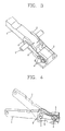
- a trip operation i.e., a circuit breaking operation
- a force that the movable contactor 1 rotates to be separated from the stationary contactor (not shown) in response to an elastic energy discharged by a trip spring (not shown) is much stronger than a frictional force which is generated when the pair of connection plates 2 are closely contacted to the side surfaces of the rear end portion of the movable contactor 1, referring to FIG. 4 , the movable contactor 1 can be fast separated from the stationary contactor to break a circuit.
- the slide type movable contactor assembly for the circuit breaker according to the present invention can employ bimetal plates, configured to press connection plates by bending toward the connection plates in response to a temperature increase due to heat generated between the movable contactor and the connection plates in a conduction state, whereby the temperature increase due to lowering of a contact pressure between the movable contactor and the connection plates in the conduction state can be minimized.
- the slide type movable contactor assembly for the circuit breaker can employ bimetal plates, configured to press connection plates by bending toward the connection plates in response to a the temperature increase due to heat generated between the movable contactor and the connection plates in a conduction state, accordingly, the failure of the circuit breaker due to deterioration, melting of the movable contactor or the connection plates caused by the temperature increase and the thusly occurred severe damage on the circuit breaker can be prevented beforehand.
Landscapes
- Physics & Mathematics (AREA)
- Electromagnetism (AREA)
- Breakers (AREA)
- Thermally Actuated Switches (AREA)
Claims (4)
- Verschiebbare bewegliche Schütz-Anordnung für Schutzschalter, aufweisend:ein beweglicher Schütz (1), der basierend auf einer Drehwelle drehbar ist;gekennzeichnet durchVerbindungsplatten (2), die eingerichtet sind, um eine Drehung des beweglichen Schutzes zu ermöglichen und gleichzeitig einen Leitungsweg durch einen Kontakt mit dem beweglichen Schütz bereitzustellen; undBimetall-Platten (6), die jeweils an beiden Seitenoberflächen der Verbindungsplatten installiert sind, und zu den Verbindungsplatten hin biegbar sind in Antwort auf eine Temperaturerhöhung in einem leitenden Zustand, um die Verbindungsplatten so zu drücken, dass sich ein Kontaktdruck der Verbindungsplatten auf den beweglichen Schütz erhöht.
- Anordnung nach Anspruch 1, wobei die Verbindungsplatten als Paar bereitgestellt werden und installiert werden, um jeweils mit beiden Seitenoberflächen des beweglichen Schützes kontaktfähig zu sein,
wobei die Bimetall-Platten als Paar bereitgestellt werden und installiert werden, um jeweils mit äußeren Oberflächen der Verbindungsplatten kontaktfähig zu sein. - Anordnung nach Anspruch 1, weiterhin aufweisend:eine Drehwelle (5), die durch die Verbindungsplatten, die Bimetall-Platten und den beweglichen Schütz eingeführt wird, und Bereitstellen eines Drehstützpunktes an den beweglichen Schütz; undeine Verbindungsbasis (3), die eingerichtet ist, um die Verbindungsplatten und die Bimetall-Platten miteinander mittels Verbindungsmittel zu verbinden und um dieselben zu stützen.
- Anordnung nach Anspruch 3, wobei das Verbindungsmittel eine Niete (4) aufweist.
Applications Claiming Priority (1)
| Application Number | Priority Date | Filing Date | Title |
|---|---|---|---|
| KR1020090082177A KR101463043B1 (ko) | 2009-09-01 | 2009-09-01 | 회로차단기의 슬라이드형 가동접촉자 어셈블리 |
Publications (2)
| Publication Number | Publication Date |
|---|---|
| EP2290667A1 EP2290667A1 (de) | 2011-03-02 |
| EP2290667B1 true EP2290667B1 (de) | 2012-07-18 |
Family
ID=43216898
Family Applications (1)
| Application Number | Title | Priority Date | Filing Date |
|---|---|---|---|
| EP10173722A Not-in-force EP2290667B1 (de) | 2009-09-01 | 2010-08-23 | Bewegliche verschiebbare Schützanordnung für Schutzschalter |
Country Status (6)
| Country | Link |
|---|---|
| US (1) | US20110048911A1 (de) |
| EP (1) | EP2290667B1 (de) |
| JP (1) | JP5038472B2 (de) |
| KR (1) | KR101463043B1 (de) |
| CN (1) | CN102005342A (de) |
| ES (1) | ES2391725T3 (de) |
Families Citing this family (4)
| Publication number | Priority date | Publication date | Assignee | Title |
|---|---|---|---|---|
| KR101752300B1 (ko) * | 2011-08-18 | 2017-07-11 | 엘에스산전 주식회사 | 배선용 차단기의 가동접촉자 어셈블리 |
| KR101318338B1 (ko) | 2012-07-10 | 2013-10-16 | 제일전기공업 주식회사 | 차단기 |
| US10732223B2 (en) * | 2017-09-14 | 2020-08-04 | Schweitzer Engineering Laboratories, Inc. | Circuit breaker health monitoring |
| CN110299253A (zh) * | 2019-07-12 | 2019-10-01 | 山东鲁冶瑞宝电气自动化有限公司 | 一种具有自行修复功能的电气触头 |
Family Cites Families (39)
| Publication number | Priority date | Publication date | Assignee | Title |
|---|---|---|---|---|
| DE965855C (de) * | 1937-12-17 | 1957-06-27 | Siemens Ag | Einrichtung an kontaktgebenden, relativ zueinander verschiebbaren Teilen, insbesondere bei Messerschaltern |
| US2303914A (en) * | 1939-09-09 | 1942-12-01 | Westinghouse Electric & Mfg Co | Circuit interrupter |
| US4123737A (en) * | 1976-11-08 | 1978-10-31 | Heinemann Electric Company | Bimetallic circuit breaker |
| US4166988A (en) * | 1978-04-19 | 1979-09-04 | General Electric Company | Compact three-pole circuit breaker |
| US4245203A (en) * | 1978-10-16 | 1981-01-13 | Westinghouse Electric Corp. | Circuit interrupter with pivoting contact arm having a clinch-type contact |
| JPS5936811Y2 (ja) * | 1979-10-12 | 1984-10-11 | 株式会社東海理化電機製作所 | サ−キツトブレ−カ− |
| FR2616583B1 (fr) * | 1987-06-09 | 1995-01-06 | Merlin Gerin | Mecanisme de commande d'un disjoncteur electrique miniature |
| JPS63308820A (ja) * | 1987-06-10 | 1988-12-16 | Fuji Electric Co Ltd | 回路遮断器の接触子装置 |
| US5146194A (en) * | 1988-10-12 | 1992-09-08 | Westinghouse Electric Corp. | Screw adjustable clinch joint with bosses |
| US5157369A (en) * | 1991-11-07 | 1992-10-20 | Rototech Electrical Components, Inc. | Circuit breaker switch |
| FR2688626B1 (fr) * | 1992-03-13 | 1994-05-06 | Merlin Gerin | Disjoncteur a boitier moule a pont de contacts freine en fin de course de repulsion. |
| US5552755A (en) * | 1992-09-11 | 1996-09-03 | Eaton Corporation | Circuit breaker with auxiliary switch actuated by cascaded actuating members |
| DE4334577C1 (de) * | 1993-10-11 | 1995-03-30 | Kloeckner Moeller Gmbh | Kontaktsystem für eine Strombegrenzungseinheit |
| IT1292453B1 (it) * | 1997-07-02 | 1999-02-08 | Aeg Niederspannungstech Gmbh | Gruppo rotante di contatti per interrutttori di alta portata |
| JP3794163B2 (ja) * | 1998-04-21 | 2006-07-05 | 三菱電機株式会社 | 回路遮断器 |
| US6114641A (en) * | 1998-05-29 | 2000-09-05 | General Electric Company | Rotary contact assembly for high ampere-rated circuit breakers |
| US6084489A (en) * | 1998-09-08 | 2000-07-04 | General Electric Company | Circuit breaker rotary contact assembly locking system |
| JP3609281B2 (ja) * | 1998-11-10 | 2005-01-12 | 三菱電機株式会社 | 回路遮断器 |
| EP1098343B1 (de) * | 1999-11-03 | 2005-09-21 | AEG Niederspannungstechnik GmbH & Co. KG | Drehkontaktanordnung für Schutzschalter |
| US6310307B1 (en) * | 1999-12-17 | 2001-10-30 | General Electric Company | Circuit breaker rotary contact arm arrangement |
| US6429759B1 (en) * | 2000-02-14 | 2002-08-06 | General Electric Company | Split and angled contacts |
| US6204743B1 (en) * | 2000-02-29 | 2001-03-20 | General Electric Company | Dual connector strap for a rotary contact circuit breaker |
| US6639168B1 (en) * | 2000-03-17 | 2003-10-28 | General Electric Company | Energy absorbing contact arm stop |
| CN2435829Y (zh) * | 2000-06-28 | 2001-06-20 | 胡广生 | 带温度补偿的隔离刀闸装置 |
| JP4186415B2 (ja) * | 2000-11-30 | 2008-11-26 | 富士電機機器制御株式会社 | 回路しゃ断器の過負荷引外し装置 |
| US6563407B2 (en) * | 2001-08-21 | 2003-05-13 | Siemens Energy & Automation, Inc. | Pivot joint for a movable contact arm in a molded case circuit breaker |
| KR100390461B1 (ko) * | 2001-08-23 | 2003-07-04 | 엘지산전 주식회사 | 회로 차단기의 트립장치부 섭동구조 |
| JP2003123611A (ja) * | 2001-10-10 | 2003-04-25 | Mitsubishi Electric Corp | 回路遮断器 |
| JP2004227900A (ja) | 2003-01-22 | 2004-08-12 | Terasaki Electric Co Ltd | 回路遮断器 |
| US6965292B2 (en) * | 2003-08-29 | 2005-11-15 | General Electric Company | Isolation cap and bushing for circuit breaker rotor assembly |
| US6878890B1 (en) * | 2003-12-19 | 2005-04-12 | Eaton Corporation | Circuit breaker lockable fastener securing a movable contact to its terminal mounting |
| US7005594B2 (en) * | 2004-04-16 | 2006-02-28 | Ls Industrial Systems Co., Ltd. | Movable contactor assembly of circuit breaker |
| KR100574788B1 (ko) * | 2004-10-07 | 2006-04-27 | 엘에스산전 주식회사 | 배선용 차단기의 접촉자 어셈블리 |
| KR100618610B1 (ko) * | 2004-12-07 | 2006-09-08 | 엘에스산전 주식회사 | 배선용 차단기의 한류기구 장치 |
| JP2007194058A (ja) | 2006-01-19 | 2007-08-02 | Fuji Electric Holdings Co Ltd | 回路遮断器 |
| US7217895B1 (en) * | 2006-07-06 | 2007-05-15 | Eaton Corporation | Electrical switching apparatus contact assembly and movable contact arm therefor |
| EP1926112A1 (de) * | 2006-11-23 | 2008-05-28 | ABB Technology AG | Elektrisches Kontaktsystem für ein elektrisches Schaltgerät |
| CN201066667Y (zh) * | 2007-05-29 | 2008-05-28 | 浙江正泰电器股份有限公司 | 一种塑壳断路器的触头系统 |
| US7667150B2 (en) * | 2008-03-04 | 2010-02-23 | Siemens Industry, Inc. | Moveable arm for a circuit breaker and method for making the same |
-
2009
- 2009-09-01 KR KR1020090082177A patent/KR101463043B1/ko active IP Right Grant
-
2010
- 2010-08-18 US US12/858,696 patent/US20110048911A1/en not_active Abandoned
- 2010-08-23 ES ES10173722T patent/ES2391725T3/es active Active
- 2010-08-23 EP EP10173722A patent/EP2290667B1/de not_active Not-in-force
- 2010-08-27 JP JP2010191144A patent/JP5038472B2/ja not_active Expired - Fee Related
- 2010-08-31 CN CN2010102692225A patent/CN102005342A/zh active Pending
Also Published As
| Publication number | Publication date |
|---|---|
| JP2011054569A (ja) | 2011-03-17 |
| CN102005342A (zh) | 2011-04-06 |
| JP5038472B2 (ja) | 2012-10-03 |
| US20110048911A1 (en) | 2011-03-03 |
| ES2391725T3 (es) | 2012-11-29 |
| KR20110024263A (ko) | 2011-03-09 |
| KR101463043B1 (ko) | 2014-11-18 |
| EP2290667A1 (de) | 2011-03-02 |
Similar Documents
| Publication | Publication Date | Title |
|---|---|---|
| US8264306B2 (en) | Movable contactor assembly for current limiting type molded case circuit breaker | |
| EP1914766B1 (de) | Beweglicher Kontaktträger für einen Leistungsschalter und Herstellungsverfahren für einen Finger davon | |
| EP2315228B1 (de) | Formgehäuse-Schutzschalter mit Sofortauslösungsmechanismus | |
| US8178804B2 (en) | Movable contactor for air circuit breaker with contact spring protecting mechanism | |
| WO2017186061A1 (zh) | 断路器触头系统及断路器 | |
| EP2290667B1 (de) | Bewegliche verschiebbare Schützanordnung für Schutzschalter | |
| EP2561535B1 (de) | Stromschalter | |
| EP0100367A1 (de) | Ausschalter | |
| US11024478B2 (en) | Overheating destructive disconnecting method for switch | |
| EP2685480B1 (de) | Kontaktanordnung eines Schalters | |
| US10141125B2 (en) | Contact for bus plug switches | |
| US5837950A (en) | Drawer type circuit breaker with drawer contacts biased against contact arcuate portions and external connection terminals | |
| JP5041542B2 (ja) | 回路遮断器のバイメタル調整構造 | |
| CN217485323U (zh) | 一种引弧装置和断路器 | |
| KR20210084627A (ko) | 이중 브레이크 포인트 차단기의 가동접촉자 기구 | |
| CN218447618U (zh) | 切换开关装置及双电源转换开关装置 | |
| KR101414592B1 (ko) | 소형 배선용 차단기의 트립장치 | |
| CN214477296U (zh) | 一种断路器的动触头系统 | |
| EP1346385B1 (de) | Automatischer strombegrenzender schutzschalter | |
| JP5093158B2 (ja) | 回路遮断器 | |
| KR100390461B1 (ko) | 회로 차단기의 트립장치부 섭동구조 | |
| CN115458348A (zh) | 切换开关装置及双电源转换开关装置 | |
| JPH04368746A (ja) | 回路遮断器 | |
| JPH08298064A (ja) | 回路遮断器 |
Legal Events
| Date | Code | Title | Description |
|---|---|---|---|
| PUAI | Public reference made under article 153(3) epc to a published international application that has entered the european phase |
Free format text: ORIGINAL CODE: 0009012 |
|
| AK | Designated contracting states |
Kind code of ref document: A1 Designated state(s): AL AT BE BG CH CY CZ DE DK EE ES FI FR GB GR HR HU IE IS IT LI LT LU LV MC MK MT NL NO PL PT RO SE SI SK SM TR |
|
| AX | Request for extension of the european patent |
Extension state: BA ME RS |
|
| 17P | Request for examination filed |
Effective date: 20110822 |
|
| GRAP | Despatch of communication of intention to grant a patent |
Free format text: ORIGINAL CODE: EPIDOSNIGR1 |
|
| RIC1 | Information provided on ipc code assigned before grant |
Ipc: H01H 73/04 20060101ALN20120217BHEP Ipc: H01H 1/22 20060101ALN20120217BHEP Ipc: H01H 1/58 20060101AFI20120217BHEP |
|
| GRAS | Grant fee paid |
Free format text: ORIGINAL CODE: EPIDOSNIGR3 |
|
| GRAA | (expected) grant |
Free format text: ORIGINAL CODE: 0009210 |
|
| AK | Designated contracting states |
Kind code of ref document: B1 Designated state(s): AL AT BE BG CH CY CZ DE DK EE ES FI FR GB GR HR HU IE IS IT LI LT LU LV MC MK MT NL NO PL PT RO SE SI SK SM TR |
|
| REG | Reference to a national code |
Ref country code: GB Ref legal event code: FG4D |
|
| REG | Reference to a national code |
Ref country code: CH Ref legal event code: EP |
|
| REG | Reference to a national code |
Ref country code: AT Ref legal event code: REF Ref document number: 567198 Country of ref document: AT Kind code of ref document: T Effective date: 20120815 Ref country code: IE Ref legal event code: FG4D |
|
| REG | Reference to a national code |
Ref country code: DE Ref legal event code: R096 Ref document number: 602010002226 Country of ref document: DE Effective date: 20120913 |
|
| REG | Reference to a national code |
Ref country code: ES Ref legal event code: FG2A Ref document number: 2391725 Country of ref document: ES Kind code of ref document: T3 Effective date: 20121129 |
|
| REG | Reference to a national code |
Ref country code: NL Ref legal event code: VDEP Effective date: 20120718 |
|
| REG | Reference to a national code |
Ref country code: AT Ref legal event code: MK05 Ref document number: 567198 Country of ref document: AT Kind code of ref document: T Effective date: 20120718 |
|
| REG | Reference to a national code |
Ref country code: LT Ref legal event code: MG4D Effective date: 20120718 |
|
| PG25 | Lapsed in a contracting state [announced via postgrant information from national office to epo] |
Ref country code: HR Free format text: LAPSE BECAUSE OF FAILURE TO SUBMIT A TRANSLATION OF THE DESCRIPTION OR TO PAY THE FEE WITHIN THE PRESCRIBED TIME-LIMIT Effective date: 20120718 Ref country code: CY Free format text: LAPSE BECAUSE OF FAILURE TO SUBMIT A TRANSLATION OF THE DESCRIPTION OR TO PAY THE FEE WITHIN THE PRESCRIBED TIME-LIMIT Effective date: 20120718 Ref country code: LT Free format text: LAPSE BECAUSE OF FAILURE TO SUBMIT A TRANSLATION OF THE DESCRIPTION OR TO PAY THE FEE WITHIN THE PRESCRIBED TIME-LIMIT Effective date: 20120718 Ref country code: AT Free format text: LAPSE BECAUSE OF FAILURE TO SUBMIT A TRANSLATION OF THE DESCRIPTION OR TO PAY THE FEE WITHIN THE PRESCRIBED TIME-LIMIT Effective date: 20120718 Ref country code: NO Free format text: LAPSE BECAUSE OF FAILURE TO SUBMIT A TRANSLATION OF THE DESCRIPTION OR TO PAY THE FEE WITHIN THE PRESCRIBED TIME-LIMIT Effective date: 20121018 Ref country code: FI Free format text: LAPSE BECAUSE OF FAILURE TO SUBMIT A TRANSLATION OF THE DESCRIPTION OR TO PAY THE FEE WITHIN THE PRESCRIBED TIME-LIMIT Effective date: 20120718 Ref country code: IS Free format text: LAPSE BECAUSE OF FAILURE TO SUBMIT A TRANSLATION OF THE DESCRIPTION OR TO PAY THE FEE WITHIN THE PRESCRIBED TIME-LIMIT Effective date: 20121118 Ref country code: BE Free format text: LAPSE BECAUSE OF FAILURE TO SUBMIT A TRANSLATION OF THE DESCRIPTION OR TO PAY THE FEE WITHIN THE PRESCRIBED TIME-LIMIT Effective date: 20120718 |
|
| PG25 | Lapsed in a contracting state [announced via postgrant information from national office to epo] |
Ref country code: SI Free format text: LAPSE BECAUSE OF FAILURE TO SUBMIT A TRANSLATION OF THE DESCRIPTION OR TO PAY THE FEE WITHIN THE PRESCRIBED TIME-LIMIT Effective date: 20120718 Ref country code: LV Free format text: LAPSE BECAUSE OF FAILURE TO SUBMIT A TRANSLATION OF THE DESCRIPTION OR TO PAY THE FEE WITHIN THE PRESCRIBED TIME-LIMIT Effective date: 20120718 Ref country code: PL Free format text: LAPSE BECAUSE OF FAILURE TO SUBMIT A TRANSLATION OF THE DESCRIPTION OR TO PAY THE FEE WITHIN THE PRESCRIBED TIME-LIMIT Effective date: 20120718 Ref country code: PT Free format text: LAPSE BECAUSE OF FAILURE TO SUBMIT A TRANSLATION OF THE DESCRIPTION OR TO PAY THE FEE WITHIN THE PRESCRIBED TIME-LIMIT Effective date: 20121119 Ref country code: GR Free format text: LAPSE BECAUSE OF FAILURE TO SUBMIT A TRANSLATION OF THE DESCRIPTION OR TO PAY THE FEE WITHIN THE PRESCRIBED TIME-LIMIT Effective date: 20121019 Ref country code: SE Free format text: LAPSE BECAUSE OF FAILURE TO SUBMIT A TRANSLATION OF THE DESCRIPTION OR TO PAY THE FEE WITHIN THE PRESCRIBED TIME-LIMIT Effective date: 20120718 |
|
| PG25 | Lapsed in a contracting state [announced via postgrant information from national office to epo] |
Ref country code: MC Free format text: LAPSE BECAUSE OF NON-PAYMENT OF DUE FEES Effective date: 20120831 Ref country code: NL Free format text: LAPSE BECAUSE OF FAILURE TO SUBMIT A TRANSLATION OF THE DESCRIPTION OR TO PAY THE FEE WITHIN THE PRESCRIBED TIME-LIMIT Effective date: 20120718 |
|
| PG25 | Lapsed in a contracting state [announced via postgrant information from national office to epo] |
Ref country code: CZ Free format text: LAPSE BECAUSE OF FAILURE TO SUBMIT A TRANSLATION OF THE DESCRIPTION OR TO PAY THE FEE WITHIN THE PRESCRIBED TIME-LIMIT Effective date: 20120718 Ref country code: DK Free format text: LAPSE BECAUSE OF FAILURE TO SUBMIT A TRANSLATION OF THE DESCRIPTION OR TO PAY THE FEE WITHIN THE PRESCRIBED TIME-LIMIT Effective date: 20120718 Ref country code: RO Free format text: LAPSE BECAUSE OF FAILURE TO SUBMIT A TRANSLATION OF THE DESCRIPTION OR TO PAY THE FEE WITHIN THE PRESCRIBED TIME-LIMIT Effective date: 20120718 Ref country code: EE Free format text: LAPSE BECAUSE OF FAILURE TO SUBMIT A TRANSLATION OF THE DESCRIPTION OR TO PAY THE FEE WITHIN THE PRESCRIBED TIME-LIMIT Effective date: 20120718 |
|
| REG | Reference to a national code |
Ref country code: IE Ref legal event code: MM4A |
|
| PLBE | No opposition filed within time limit |
Free format text: ORIGINAL CODE: 0009261 |
|
| STAA | Information on the status of an ep patent application or granted ep patent |
Free format text: STATUS: NO OPPOSITION FILED WITHIN TIME LIMIT |
|
| PG25 | Lapsed in a contracting state [announced via postgrant information from national office to epo] |
Ref country code: SK Free format text: LAPSE BECAUSE OF FAILURE TO SUBMIT A TRANSLATION OF THE DESCRIPTION OR TO PAY THE FEE WITHIN THE PRESCRIBED TIME-LIMIT Effective date: 20120718 |
|
| 26N | No opposition filed |
Effective date: 20130419 |
|
| PG25 | Lapsed in a contracting state [announced via postgrant information from national office to epo] |
Ref country code: IE Free format text: LAPSE BECAUSE OF NON-PAYMENT OF DUE FEES Effective date: 20120823 Ref country code: BG Free format text: LAPSE BECAUSE OF FAILURE TO SUBMIT A TRANSLATION OF THE DESCRIPTION OR TO PAY THE FEE WITHIN THE PRESCRIBED TIME-LIMIT Effective date: 20121018 |
|
| REG | Reference to a national code |
Ref country code: DE Ref legal event code: R097 Ref document number: 602010002226 Country of ref document: DE Effective date: 20130419 |
|
| PG25 | Lapsed in a contracting state [announced via postgrant information from national office to epo] |
Ref country code: AL Free format text: LAPSE BECAUSE OF FAILURE TO SUBMIT A TRANSLATION OF THE DESCRIPTION OR TO PAY THE FEE WITHIN THE PRESCRIBED TIME-LIMIT Effective date: 20120718 Ref country code: MT Free format text: LAPSE BECAUSE OF FAILURE TO SUBMIT A TRANSLATION OF THE DESCRIPTION OR TO PAY THE FEE WITHIN THE PRESCRIBED TIME-LIMIT Effective date: 20120718 |
|
| PG25 | Lapsed in a contracting state [announced via postgrant information from national office to epo] |
Ref country code: TR Free format text: LAPSE BECAUSE OF FAILURE TO SUBMIT A TRANSLATION OF THE DESCRIPTION OR TO PAY THE FEE WITHIN THE PRESCRIBED TIME-LIMIT Effective date: 20120718 |
|
| PG25 | Lapsed in a contracting state [announced via postgrant information from national office to epo] |
Ref country code: SM Free format text: LAPSE BECAUSE OF FAILURE TO SUBMIT A TRANSLATION OF THE DESCRIPTION OR TO PAY THE FEE WITHIN THE PRESCRIBED TIME-LIMIT Effective date: 20120718 Ref country code: LU Free format text: LAPSE BECAUSE OF NON-PAYMENT OF DUE FEES Effective date: 20120823 |
|
| PG25 | Lapsed in a contracting state [announced via postgrant information from national office to epo] |
Ref country code: HU Free format text: LAPSE BECAUSE OF FAILURE TO SUBMIT A TRANSLATION OF THE DESCRIPTION OR TO PAY THE FEE WITHIN THE PRESCRIBED TIME-LIMIT Effective date: 20100823 |
|
| REG | Reference to a national code |
Ref country code: CH Ref legal event code: PL |
|
| PG25 | Lapsed in a contracting state [announced via postgrant information from national office to epo] |
Ref country code: LI Free format text: LAPSE BECAUSE OF NON-PAYMENT OF DUE FEES Effective date: 20140831 Ref country code: CH Free format text: LAPSE BECAUSE OF NON-PAYMENT OF DUE FEES Effective date: 20140831 |
|
| PG25 | Lapsed in a contracting state [announced via postgrant information from national office to epo] |
Ref country code: MK Free format text: LAPSE BECAUSE OF FAILURE TO SUBMIT A TRANSLATION OF THE DESCRIPTION OR TO PAY THE FEE WITHIN THE PRESCRIBED TIME-LIMIT Effective date: 20120718 |
|
| REG | Reference to a national code |
Ref country code: FR Ref legal event code: PLFP Year of fee payment: 7 |
|
| REG | Reference to a national code |
Ref country code: FR Ref legal event code: PLFP Year of fee payment: 8 |
|
| REG | Reference to a national code |
Ref country code: FR Ref legal event code: PLFP Year of fee payment: 9 |
|
| PGFP | Annual fee paid to national office [announced via postgrant information from national office to epo] |
Ref country code: FR Payment date: 20200609 Year of fee payment: 11 |
|
| PGFP | Annual fee paid to national office [announced via postgrant information from national office to epo] |
Ref country code: GB Payment date: 20200608 Year of fee payment: 11 |
|
| PGFP | Annual fee paid to national office [announced via postgrant information from national office to epo] |
Ref country code: DE Payment date: 20200605 Year of fee payment: 11 Ref country code: ES Payment date: 20200911 Year of fee payment: 11 |
|
| PGFP | Annual fee paid to national office [announced via postgrant information from national office to epo] |
Ref country code: IT Payment date: 20200813 Year of fee payment: 11 |
|
| REG | Reference to a national code |
Ref country code: DE Ref legal event code: R119 Ref document number: 602010002226 Country of ref document: DE |
|
| GBPC | Gb: european patent ceased through non-payment of renewal fee |
Effective date: 20210823 |
|
| PG25 | Lapsed in a contracting state [announced via postgrant information from national office to epo] |
Ref country code: IT Free format text: LAPSE BECAUSE OF NON-PAYMENT OF DUE FEES Effective date: 20210823 Ref country code: GB Free format text: LAPSE BECAUSE OF NON-PAYMENT OF DUE FEES Effective date: 20210823 Ref country code: FR Free format text: LAPSE BECAUSE OF NON-PAYMENT OF DUE FEES Effective date: 20210831 Ref country code: DE Free format text: LAPSE BECAUSE OF NON-PAYMENT OF DUE FEES Effective date: 20220301 |
|
| REG | Reference to a national code |
Ref country code: ES Ref legal event code: FD2A Effective date: 20221027 |
|
| PG25 | Lapsed in a contracting state [announced via postgrant information from national office to epo] |
Ref country code: ES Free format text: LAPSE BECAUSE OF NON-PAYMENT OF DUE FEES Effective date: 20210824 |