EP1510747A1 - Vacuum thermal insulating material, process for producing the same and refrigerator including the same - Google Patents
Vacuum thermal insulating material, process for producing the same and refrigerator including the same Download PDFInfo
- Publication number
- EP1510747A1 EP1510747A1 EP03730754A EP03730754A EP1510747A1 EP 1510747 A1 EP1510747 A1 EP 1510747A1 EP 03730754 A EP03730754 A EP 03730754A EP 03730754 A EP03730754 A EP 03730754A EP 1510747 A1 EP1510747 A1 EP 1510747A1
- Authority
- EP
- European Patent Office
- Prior art keywords
- heat insulator
- vacuum heat
- core
- binding agent
- fibers
- Prior art date
- Legal status (The legal status is an assumption and is not a legal conclusion. Google has not performed a legal analysis and makes no representation as to the accuracy of the status listed.)
- Granted
Links
Images

Classifications
-
- F—MECHANICAL ENGINEERING; LIGHTING; HEATING; WEAPONS; BLASTING
- F16—ENGINEERING ELEMENTS AND UNITS; GENERAL MEASURES FOR PRODUCING AND MAINTAINING EFFECTIVE FUNCTIONING OF MACHINES OR INSTALLATIONS; THERMAL INSULATION IN GENERAL
- F16L—PIPES; JOINTS OR FITTINGS FOR PIPES; SUPPORTS FOR PIPES, CABLES OR PROTECTIVE TUBING; MEANS FOR THERMAL INSULATION IN GENERAL
- F16L59/00—Thermal insulation in general
- F16L59/06—Arrangements using an air layer or vacuum
- F16L59/065—Arrangements using an air layer or vacuum using vacuum
-
- F—MECHANICAL ENGINEERING; LIGHTING; HEATING; WEAPONS; BLASTING
- F25—REFRIGERATION OR COOLING; COMBINED HEATING AND REFRIGERATION SYSTEMS; HEAT PUMP SYSTEMS; MANUFACTURE OR STORAGE OF ICE; LIQUEFACTION SOLIDIFICATION OF GASES
- F25D—REFRIGERATORS; COLD ROOMS; ICE-BOXES; COOLING OR FREEZING APPARATUS NOT OTHERWISE PROVIDED FOR
- F25D23/00—General constructional features
- F25D23/06—Walls
- F25D23/065—Details
-
- F—MECHANICAL ENGINEERING; LIGHTING; HEATING; WEAPONS; BLASTING
- F25—REFRIGERATION OR COOLING; COMBINED HEATING AND REFRIGERATION SYSTEMS; HEAT PUMP SYSTEMS; MANUFACTURE OR STORAGE OF ICE; LIQUEFACTION SOLIDIFICATION OF GASES
- F25D—REFRIGERATORS; COLD ROOMS; ICE-BOXES; COOLING OR FREEZING APPARATUS NOT OTHERWISE PROVIDED FOR
- F25D2201/00—Insulation
- F25D2201/10—Insulation with respect to heat
- F25D2201/12—Insulation with respect to heat using an insulating packing material
-
- F—MECHANICAL ENGINEERING; LIGHTING; HEATING; WEAPONS; BLASTING
- F25—REFRIGERATION OR COOLING; COMBINED HEATING AND REFRIGERATION SYSTEMS; HEAT PUMP SYSTEMS; MANUFACTURE OR STORAGE OF ICE; LIQUEFACTION SOLIDIFICATION OF GASES
- F25D—REFRIGERATORS; COLD ROOMS; ICE-BOXES; COOLING OR FREEZING APPARATUS NOT OTHERWISE PROVIDED FOR
- F25D2201/00—Insulation
- F25D2201/10—Insulation with respect to heat
- F25D2201/14—Insulation with respect to heat using subatmospheric pressure
-
- F—MECHANICAL ENGINEERING; LIGHTING; HEATING; WEAPONS; BLASTING
- F25—REFRIGERATION OR COOLING; COMBINED HEATING AND REFRIGERATION SYSTEMS; HEAT PUMP SYSTEMS; MANUFACTURE OR STORAGE OF ICE; LIQUEFACTION SOLIDIFICATION OF GASES
- F25D—REFRIGERATORS; COLD ROOMS; ICE-BOXES; COOLING OR FREEZING APPARATUS NOT OTHERWISE PROVIDED FOR
- F25D2500/00—Problems to be solved
- F25D2500/02—Geometry problems
-
- Y—GENERAL TAGGING OF NEW TECHNOLOGICAL DEVELOPMENTS; GENERAL TAGGING OF CROSS-SECTIONAL TECHNOLOGIES SPANNING OVER SEVERAL SECTIONS OF THE IPC; TECHNICAL SUBJECTS COVERED BY FORMER USPC CROSS-REFERENCE ART COLLECTIONS [XRACs] AND DIGESTS
- Y10—TECHNICAL SUBJECTS COVERED BY FORMER USPC
- Y10T—TECHNICAL SUBJECTS COVERED BY FORMER US CLASSIFICATION
- Y10T428/00—Stock material or miscellaneous articles
- Y10T428/23—Sheet including cover or casing
- Y10T428/231—Filled with gas other than air; or under vacuum
Definitions
- the present invention relates to a vacuum heat insulator using a core formed to be plate-shaped, an adiabatic body, an adiabatic box body, an adiabatic door, a storage house, and a refrigerator, to which the vacuum heat insulator is applied, a method of manufacturing the vacuum heat insulator, and a method of manufacturing the core for the vacuum heat insulator.
- heat insulators having an excellent adiabatic performance (heat insulating efficiency) are demanded for thermally insulated equipments such as refrigerators, freezers, automatic vending machines, etc. from the viewpoint of efficient use of heat.
- heat insulators fiber materials such as glass wool, etc. and foam such as urethane foam, etc. are used. In order to enhance these heat insulators in adiabatic property, it is necessary to increase the heat insulator in thickness. Since there is a limitation to a space, into which heat insulators can be filled, however, such measures cannot be applied in case of the necessity for space saving and effective spatial use.
- Vacuum heat insulators are ones, in which a core is covered by an exterior covering having a gas-barrier quality, an interior of the exterior covering is reduced in pressure, and an opening of the exterior covering is fused.
- Conventional vacuum heat insulators include one, in which an aggregate of inorganic fibers such as glass wool, etc. is cured by a binding agent to be used for a core.
- Such vacuum heat insulators are described in, for example, United States Patent Publication No. 4,726,974 and Japanese Patent Unexamined Publication No.H8-28776. Since an aggregate of inorganic fibers is cured by means of a binding agent, the vacuum heat insulator has a sufficient strength and a sufficient planarity to be excellent in handling quality.
- such a vacuum heat insulator has the adiabatic performance (thermal conductivity) of about 0.007 W/mK at the degree of vacuum of 1.33 Pa, the adiabatic performance is same as that of a vacuum heat insulator in which powder filling is used as a core. Thus it is demanded to enhance the adiabatic performance beyond such adiabatic performance.
- a vacuum heat insulator according to the present invention includes a core molded to be plate-shaped with the use of a binding agent.
- the vacuum heat insulator assumes any one of the following configurations.
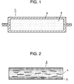
- Fig. 1 is a cross sectional view showing a vacuum heat insulator according to a first exemplary embodiment of the present invention.
- Vacuum heat insulator 1 according to this embodiment includes core 2 and exterior covering 3 covering the same.
- Exterior covering 3 includes a gas-barrier film having a gas-barrier layer and a thermal fusing layer. An interior of exterior covering 3 is reduced in pressure. An opening of exterior covering 3 is thermally fused.
- Core 2 is formed by curing an inorganic fiber aggregate, which is laminated by a dry process to have an average fiber diameter of 5 ⁇ m, by means of a binding agent to make the same plate-shaped.
- a method of manufacturing vacuum heat insulator 1 will be simply described below. After core 2 is dried at 140°C for one hour, it is inserted into exterior covering 3. After an interior of exterior covering 3 is reduced to 13.3 Pa in pressure, its opening is bonded by thermal fusing.
- the adiabatic performance (thermal conductivity) of vacuum heat insulator 1 fabricated in this manner is measured at an average temperature 24°C to be 0.0035 W/mK. Void diameter between fibers is calculated by the mercury porosity analysis to present 40 ⁇ m. Since core 2 cured by a binding agent to be made plate-shaped is used, surfaces of vacuum heat insulator 1 is sufficiently planar and also sufficient in stiffness.
- Void diameter corresponding to those respective pressures, under which mercury is injected, is obtained from an amount of mercury on the basis of Formula 1. Void diameter is determined by calculation from the void diameter distribution ranging from 0.1 ⁇ m to 40 ⁇ m.
- Core 2 of vacuum heat insulator 1 is formed from an aggregate of inorganic fibers, Core 2 has a thickness of 15 mm. Core 2 has a void diameter of 40 ⁇ m and a percentage of the voids of 94 %. Core 2 has a decreasing rate of 10 % in thickness due to reduction in pressure, and has a density (bulk density) of 150 kg/m 3 , and pressure in vacuum heat insulator 1 is 13.3 Pa.
- an apparent thermal conductivity is the sum of gas thermal conductivity ( ⁇ g), solid thermal conductivity ( ⁇ s), radiation thermal conductivity ( ⁇ r), and convection thermal conductivity ( ⁇ c), and is represented by Formula 2.
- ⁇ app ⁇ g + ⁇ s + ⁇ r + ⁇ c
- thermal conduction through fibers decreases.
- Thermal conduction through contact points of adjacent fibers is also decreased and contact resistance is increased. Thereby, solid thermal conduction is decreased.
- An increase in percentage of the voids leads to an increase in ratio, at which gas thermal conduction occupies all thermal conduction.
- gaseous molecules are limited in movement and a component of gas thermal conduction is decreased, so that gas thermal conduction is decreased.
- inorganic fibers are decreased in productivity.
- Such inorganic fibers become tangled in a complex manner to be increased in probability, in which they present a fiber arrangement in parallel to a direction of thermal conduction, to be increased in quantity of thermal conduction.
- the average fiber diameter is fine, complex tangling is liable to generate an aggregate and to lead to an increase in percentage of the voids while voids in and between the aggregate are increased.
- the average fiber diameter over 10 ⁇ m inorganic fibers are increased in productivity but quantity of thermal conduction through fibers is increased. Further, because of a decrease in contact resistance, solid thermal conduction is increased.
- An increase in fiber diameter leads to an increase in void diameter between fibers. Based on these matters, by using an aggregate of inorganic fibers having an average fiber diameter of at least 0.1 ⁇ m but at most 10 ⁇ m, a vacuum heat insulator is enhanced in adiabatic performance without deterioration in productivity.
- a core having 80 % or more of percentage of the voids and at most 40 ⁇ m of void diameter between fibers It is preferable to use a core having 80 % or more of percentage of the voids and at most 40 ⁇ m of void diameter between fibers. With such arrangement, the solid thermal conduction is decreased, gas thermal conduction is made dominant, and the gas thermal conduction is decreased.
- a vacuum heat insulator By curing an aggregate of inorganic fibers with the use of a binder agent, a vacuum heat insulator being excellent in surface flatness and stiffness is obtained and sharply improved in service condition, productivity, and quality of handling.
- Core 2 according to this embodiment is structured such that a decreasing rate of thickness due to reduction in pressure becomes 10 % or lower. Therefore, vacuum heat insulator 1 is restricted in dimensional change before and after fabrication. That is, vacuum heat insulator 1 is sharply improved in dimensional stability.
- Moisture adsorbents and gas adsorbents may be charged into vacuum heat insulator 1. With such a manner, the vacuum heat insulator is enhanced in reliability.
- the mechanism of adsorption may be any one of physical adsorption, chemical adsorption, occulusion, sorption, etc. while substances acting as a non-evaporation type getter are favorable.
- physical adsorbents include synthetic zeolite, activated carbon, activated alumina, silica gel, dawsonite, hydrotalcite, etc.
- a fibrous material of core 2 can make use of fiber of an inorganic material, such as glass wool, ceramic fiber, rock wool, glass fiber, alumina fiber, silica-alumina fiber, silica fiber, silicone carbide fiber, etc. having an average fiber diameter of at least 0.1 ⁇ m but at most 10 ⁇ m. Taking account of productivity, at least 0.8 ⁇ m but at most 10 ⁇ m is desirable. Although the fiber length is not specifically specified, at most 500 mm and further at most 200 mm are desirable.
- While a fiber aggregate laminated by the dry process is used for core 2, it is not limited to the dry process.
- the core is not limited to a laminate.
- heat transfer between respective layers is hard to occur.
- a continuous porous structure is formed in entire core 2, and expansion of an air remaining between layers of exterior covering 3 and core 2 at the time of reduction in pressure is prevented by the continuous porous structure. Therefore, it is possible to avoid a situation in which fused edges of exterior covering 3 are broken, so that quality is made stable.
- exterior covering 3 one capable of cutting off between core 2 and an outside air is used.
- a laminate material of metallic foil made of stainless steel, aluminum, iron, etc. and plastic film is used.
- Such a laminate material is composed of at least a gas-barrier layer and a thermally fusing layer.
- a surface protecting layer or the like may be provided, if required.
- the gas-barrier layer it is possible to use metallic foil, plastic film on which metal, inorganic oxide, diamond-like carbon, or the like is deposited, or the like. Materials are not specifically limitative provided that they are used for the purpose of lessening gas permeation. Metal deposit films are desirable in order to restrict heat leak and to provide an excellent adiabatic performance. While foil made of aluminum, stainless steel, iron, etc.
- a material for metal deposition is not specifically limited to aluminum, cobalt, nickel, zinc, copper, silver, a mixture thereof, etc.
- a backing film being subjected to metallic deposition polyethylene terephthalate, ethylene-vinyl alcohol copolymer resin, polyethylene naphthalate, nylon, polyamide, polyimide, etc. are preferred.
- a material for deposition of inorganic oxide is not limited silica, alumina, etc.
- thermal fusing layer Used as a thermal fusing layer are a low-density polyethylene film, a high-density polyethylene film, a non-drawn polyethylene terephthalate film, a polypropylene film, a polyacrylonitrile film, an ethylene-vinyl alcohol copolymer film, a mixture thereof, etc.
- the layer is not limited to these films. It is suitable that the thermal fusing layer have a thickness of 25 to 60 ⁇ m. This is because it is directed to providing balance among stability of a sealing quality in a process of pressure reduction and sealing, restriction on entry of gases from end surfaces of thermally fused portions, and heat leak from surfaces due to thermal conduction in case of a metallic foil as the gas-barrier layer.
- Drawn products of a polyethylene terephthalate film or a polypropylene film are used for the surface protective layer.
- a nylon film outside thereof flexibility is improved and durability against folding is improved.
- Metallic containers made of iron sheet, stainless sheet, zinc sheet, or the like may be used for exterior covering 3.
- Exterior covering 3 may be bag-shaped like four-side sealed bags, gusset bags, L-shaped bags, pillow bags, center tape sealed bags, or the like and is not specifically limitative.
- Metallic sheet may be formed to be rectangular-shaped for use.
- a linear low-density polyethylene film (referred below to as LLDPE) having a thickness of 50 ⁇ m is used as the thermal fusing layer.
- Used as the gas-barrier layer is a film formed by sticking two films, each having evaporated aluminum together at evaporated aluminum surfaces.
- One of the films is an ethylene-vinyl alcohol copolymer film (referred below to as EVOH) having a thickness of 15 ⁇ m with an evaporated aluminum of a film thickness of 450 angstrom thereon.
- the other of the films is a polyethylene terephthalate film (referred below to as PET) having a thickness of 12 ⁇ m with an evaporated aluminum of a film thickness of 450 angstrom thereon.
- LLDPE of the thermal fusing layer and EVOH of the gas-barrier layer are dry-laminated to constitute one of exterior coverings 3.
- the other of exterior coverings 3 uses LLDPE having a thickness of 50 ⁇ m as the thermal fusing layer, and an aluminum foil having a thickness of 6 ⁇ m thereon as the gas-barrier layer.
- Nylon having a thickness of 12 ⁇ m is used thereon as the protective layer and nylon having a thickness of 12 ⁇ m is used as the outermost layer.
- a method of manufacturing a vacuum heat insulator includes first fabricating exterior covering 3, thereafter inserting core 2 into exterior covering 3, reducing pressure in the same, and sealing the same.
- core 2 and an exterior covering composed of a roll-shaped or sheet-shaped laminate film may be placed in a decompression tank, andvacuumheat insulator 1 maybe fabricated by thermally fusing the exterior covering after the exterior covering is put in a state of being placed along core 2.
- Vacuum heat insulator 1 may be manufactured by directly reducing pressure in exterior covering 3 with core 2 inserted thereinto and sealing the opening of exterior covering 3.
- Vacuum heat insulator 1 may be manufactured by inserting board-shaped core 1 into a container which is formed from a metallic sheet, connecting a vacuum pump and the metallic container by means of a pipe to reduce pressure in the container, and thereafter sealing and cutting the pipe. In this manner, there are various methods but the method is not limitative.
- the core may be dried prior to insertion into the exterior covering, and adsorbents may be inserted together with the core when inserted into the exterior covering.
- Vacuum heat insulator 1 is the same in fundamental constitution as that of the first exemplary embodiment shown in Fig. 1. This embodiment is different from the first exemplary embodiment in the structure of core 2.
- Core 2 in this embodiment is formed by coating an inorganic fiber aggregate which is laminated by the dry process to have an average fiber diameter of 7 ⁇ m, with a solid component of a phenol resin of 10 wt % as a binding agent and curing the same to make the same plate-shaped.
- the adiabatic performance (thermal conductivity) of vacuum heat insulator 1 fabricated in this manner is measured at an average temperature 24°C to be 0.0041 W/mK. Curing is adequately achieved since addition of the binding agent is 10 wt %. Since a decreasing rate of the thickness of core 2 due to reduction in pressure becomes 6 %, atmospheric compression is small when vacuum heat insulator 1 is made, and the dimensional stability is sharply improved.
- Core 2 of vacuum heat insulator 1 is composed of an aggregate of inorganic fibers having a fiber diameter of 7 ⁇ m and has a thickness of 15 mm. Core 2 has a void diameter of 40 ⁇ m and a percentage of the voids of 92 %. A decreasing rate of the thickness of core 2 due to reduction in pressure is 6 %, a density (bulk density) of the core is 200 kg/m 3 , and pressure in vacuum heat insulator 1 is 13.3 Pa.
- a binding agent in this embodiment includes an organic binder having at least a thermosetting property.
- Fatty acid denatured alkyd resins, amino resins, epoxy resins, polyamide resins, urethane resins, acrylic resins, petroleum resins, urea resins, melamine resins, xylene resins, furan resins, etc. in addition to phenol resins may be used as such organic binder.
- An addition of the binding agent is appropriately 8 to 20 wt % relative to a weight of the core and preferably 10 wt %.
- this embodiment includes an organic binder having at least a thermosetting property in addition to the constitution of the first exemplary embodiment.
- an aggregate of inorganic fibers prior to curing of the binding agent can be subjected to compression molding into an optional shape with the use of a molding die.
- the binding agent is cured by heating, so that the molded core is made stable in shape.
- Vacuum heat insulator 1 is the same in fundamental constitution as that of the first exemplary embodiment shown in Fig. 1. This embodiment is different from the first exemplary embodiment in the structure of core 2.
- Core 2 in this embodiment is formed by coating an inorganic fiber aggregate which is laminated by the dry process to have an average fiber diameter of 0.8 ⁇ m, with a phenol resin of 10 wt % as a solid component and curing the same to make the same plate-shaped.
- the adiabatic performance (thermal conductivity) of vacuum heat insulator 1 fabricated in this manner is measured at an average temperature 24°C to be 0.0024 W/mK. Curing is adequately achieved since addition of the binding agent is 10 wt %. Since a decreasing rate of the thickness of core 2 due to reduction in pressure is 5 %, atmospheric compression is small when vacuum heat insulator 1 is made, and the dimensional stability is sharply improved.
- Core 2 of vacuum heat insulator 1 is composed of an aggregate of inorganic fibers having a fiber diameter of 0.8 ⁇ m and has a thickness of 15 mm. Core 2 has a void diameter of 9 ⁇ m and a percentage of the voids of 92 %. A decreasing rate of the thickness of core 2 due to reduction in pressure is 5 %, a density (bulk density) of the core is 200 kg/m 3 , and pressure in vacuum heat insulator 1 is 13.3 Pa.
- a vacuum heat insulator which is easy to mold, stable in shape, and excellent in adiabatic property, is obtained in the same manner as in the second exemplary embodiment.
- Vacuum heat insulator 1 is the same in fundamental constitution as that of the first exemplary embodiment shown in Fig. 1.
- This Embodiment is different from the first exemplary embodiment in the structure of core 2.
- Core 2 in this embodiment is formed by coating an inorganic fiber aggregate which is laminated by the dry process to have an average fiber diameter of 3.5 ⁇ m, with a binding agent of 10 wt % as a solid component and curing the same to make the same plate-shaped.
- the binding agent includes water glass differently from the first and second embodiments.
- the adiabatic performance (thermal conductivity) of vacuum heat insulator 1 fabricated in this manner is measured at an average temperature 24°C to be 0.0029 W/mK. Curing is adequately achieved since addition of the binding agent is 10 wt %. Since a decreasing rate of the thickness of core 2 due to reduction in pressure is 10 %, atmospheric compression is small when vacuum heat insulator 1 is made, and the dimensional stability is sharply improved.
- Core 2 of vacuum heat insulator 1 is composed of an aggregate of inorganic fibers having a fiber diameter of 3.5 ⁇ m and has a thickness of 15 mm. Core 2 has a void diameter of 30 ⁇ m and a percentage of the voids of 90 %. A decreasing rate of the thickness of core 2 due to reduction in pressure is 10 %, a density (bulk density) of the core is 250 kg/m 3 , and pressure in vacuum heat insulator 1 is 13.3 Pa.
- a vacuum heat insulator which is easy to mold, stable in shape, and excellent in adiabatic property, is obtained in the same manner as in the second embodiment. Since the density (bulk density) of the core is 250 kg/ m 3 , the core is further increased in stiffness to lead an increase in mechanical strength when vacuum heat insulator 1 is made, so that shape stability is improved in use.
- the binder in this embodiment includes an inorganic binder having at least a thermosetting property.
- Alumina sol, colloidal silica, organo-silica sol, sodium silicate, lithium silicate, potassium silicate, silica magnesium oxide, gypsum, boric acid compounds, phosphoric acid compounds, alkyl silicate, etc. in addition to water glass may be used as such inorganic binder.
- Boric acid base compounds include respective hydrates of boric acid, metaboric acid, boric oxide and tetra sodium borate, or anhydrates of sodium borate group, ammonium borate group, lithium borate group, manganese borate group, calcium borate group, aluminum borate group, zinc borate group, perborate group, alkylborate group, boroxine derivatives, etc.
- Phosphoric acid compounds include phosphoric acid, phosphorus oxides such as diphosphate pentaoxide or the like, or monobasic phosphate, dibasic phosphate, tribasic phosphate, pyrophosphate, tripolyphosphate, metaphosphate, etc., and their sodium salt, potassium salt, ammonium salt, magnesium salt, aluminum salt, etc.
- glassforming substances, or water soluble substances are preferable to include, for example, boric acid, metaboric acid, boric oxide, borax, or phosphoric acid, monobasic aluminum phosphate, sodium hexametaphosphorate, etc.
- One or two or more of the substances described above are mixed, or other binding agents are mixed, or they are diluted to be used as a binding agent for moldings to fabricate a core.
- An addition of the binding agent is appropriately 0.1 to 20 wt % relative to a weight of the core and preferably 1 to 10 wt %.
- organic binder described with respect to the second and third embodiments and the inorganic binder described above may be combined to be used a binding agent.
- Vacuum heat insulator 1 is the same in fundamental constitution as that of the first exemplary embodiment shown in Fig. 1.
- This embodiment is the same in fundamental materials as those in the second exemplary embodiment.
- This embodiment is different from the second embodiment in the density of core 2. That is, according to this embodiment, an inorganic fiber aggregate which is laminated by the dry process to have an average fiber diameter of 0.8 ⁇ m is coated with a solid component of a binding agent of 10 wt % and cured to be made plate-shaped, and its density (bulk density) is 250 kg/m 3 .
- the adiabatic performance (thermal conductivity) of vacuum heat insulator 1 fabricated in this manner is measured at an average temperature 24°C to be 0.0023 W/mK. Curing is adequately achieved since addition of the binding agent is 10 wt %. Further, since a decreasing rate of the thickness of core 2 due to reduction in pressure is 2 %, atmospheric compression is small when vacuum heat insulator 1 is made, and the dimensional stability is sharply improved.
- Core 2 of vacuum heat insulator 1 is composed of an aggregate of inorganic fibers having a fiber diameter of 0.8 ⁇ m and has a thickness of 15 mm. Core 2 has a void diameter of 8 ⁇ m and a percentage of the voids of 90 %. A decreasing rate of the thickness of core 2 due to reduction in pressure is 2 %, a density (bulk density) of the core is 250 kg/m 3 , and pressure in vacuum heat insulator 1 is 13.3 Pa.
- a vacuum heat insulator which is easy to mold, stable in shape, and excellent in adiabatic property, is obtained in the same manner as in the fourth exemplary embodiment.
- Core 2 appropriately has a density of 100 to 400 kg/m 3 and preferably 150 to 250 kg/m 3 .
- density of the core exceeds 400 kg/m 3 , shape stability is further improved but solid thermal conduction is increased to lead to a decrease in adiabatic performance and an increase in weight, which makes handling hard.
- density of the core is less than 100 kg/m 3 , vacuum heat insulator 1 is decreased in strength. This is the same with other embodiments.
- a binding agent used in this embodiment may include an inorganic binder in the same manner as in the fourth exemplary embodiment.
- a core of the vacuum heat insulator has a thickness of 15 mm, a void diameter of 35 ⁇ m and a percentage of the voids of 93 %.
- a decreasing rate of the thickness of the core due to reduction in pressure is 80 %, a density (bulk density) of the core is 180 kg/m 3 , and pressure in the vacuum heat insulator is 13.3 Pa.
- the thermal conductivity of the vacuum heat insulator is favorably 0. 0022 W/mK
- surfaces of the vacuum heat insulator become wavy and the vacuum heat insulator is not sufficient in performance with respect to surface flatness and stiffness because the inorganic fiber aggregate is not cured by a binding agent.
- the decreasing rate of the thickness of the core due to reduction in pressure is as large as 80 %, and the vacuum heat insulator is poor in dimensional stability to be unfit for use.
- an inorganic fiber aggregate having an average fiber diameter of 0.8 ⁇ m is used as a core of a vacuum heat insulator and dried and compressed after being immersed in water.
- the inorganic fiber includes ceramic fibers or the like of which components are not soluble in water. Fabrication is performed in the same manner as the first exemplary embodiment with respect to other matters.
- a core of the vacuum heat insulator has a thickness of 15 mm, a void diameter of 10 ⁇ m and a percentage of the voids of 92 %.
- a decreasing rate of the thickness of the core due to reduction in pressure is 40 %, a density of the core is 200 kg/m 3 , and pressure in the vacuum heat insulator is 13.3 Pa.
- the thermal conductivity of the vacuum heat insulator is favorably 0.0028 W/mK
- surfaces of the vacuum heat insulator become wavy and the vacuum heat insulator is not sufficient in performance with respect to surface flatness and stiffness because the inorganic fiber aggregate is not cured by a binding agent.
- a decreasing rate of the thickness of the core due to reduction in pressure is as large as 40 %, and the vacuum heat insulator is poor in dimensional stability.
- a core of the vacuum heat insulator has a thickness of 15 mm, a void diameter of 20 ⁇ m and a percentage of the voids of 97 %.
- a decreasing rate of the thickness of the core due to reduction in pressure is 66 %, a density of the core is 65 kg/m 3 , and pressure in the vacuum heat insulator is 13.3 Pa.
- the thermal conductivity of the vacuum heat insulator is favorably 0.0041 W/mK
- the density of the core is 65 kg/m 3
- the core is not sufficient in stiffness. Since the density of the core is 65 kg/m 3 , the decreasing rate of the thickness of the core due to reduction in pressure is as large as 66 %, and the vacuum heat insulator is poor in dimensional stability.
- a core of a vacuum heat insulator includes an inorganic fiber aggregate having an average fiber diameter of 4.5 ⁇ m and a density of the core is 700 kg/m 3 . Fabrication is performed in the same manner as the first exemplary embodiment with respect to other matters.
- the core of the vacuum heat insulator has a thickness of 15 mm, a void diameter of 35 ⁇ m and a percentage of the voids of 72 %.
- a decreasing rate of the thickness of the core due to reduction in pressure is 1 %, a density of the core is 700 kg/m 3 , and pressure in the vacuum heat insulator is 13.3 Pa.
- the core of the vacuum heat insulator is harder than needed. Therefore, the decreasing rate of the thickness of the core due to reduction in pressure becomes 1 %, so that the vacuum heat insulator is improved in dimensional stability but sharply decreased in workability. While the core is further increased in stiffness and the vacuum heat insulator is enhanced in dimensional stability when being formed, solid thermal conduction is increased because solid point contact is increased. Therefore, as compared with a core containing no binding agent, the adiabatic performance is sharply decreased and the thermal conductivity is 0.0058 W/mK.
- an inorganic fiber aggregate used for a core of a vacuum heat insulator be formed to be plate-shaped and cured by a binding agent. It is found that inorganic fibers preferably have an average fiber diameter of at least 0.1 ⁇ m but at most 10 ⁇ m, voids defined by inorganic fibers have a void diameter of at most 40 ⁇ m and a core have a percentage of the voids of at least 80 %. The reason for this has been described with respect to the first exemplary embodiment and so a detailed explanation is omitted.
- a vacuum heat insulator can be made excellent in surface flatness and stiffness and sharply improved in service condition, productivity, and quality of handling.
- the core when a core has a density of at least 100 kg/m 3 but at most 400 kg/m 3 , the core can be increased in stiffness while maintained in adiabatic performance, and the vacuum heat insulator is increased in mechanical strength when made and enhanced in shape stability in use.
- At least an organic binder, or at least an inorganic binder is preferable as a binding agent to fix an inorganic fiber aggregate in a molded form.
- a binding agent is more preferable to have a thermosetting property.
- An inorganic fiber aggregate is described as being used for a core of a vacuum heat insulator.
- a material of fibers is not limited thereto but may be an organic material.
- Organic fibers including natural fibers such as cotton, etc. and synthetic fibers such as polyester, nylon, aramid, etc. can be used for the organic fibers.
- Fig. 1 Across sectional view of a vacuum heat insulator according to a sixth exemplary embodiment of the invention is the same as Fig. 1 in the first exemplary embodiment, and the sixth exemplary embodiment is the same in fundamental constitution except a core as the first exemplary embodiment.
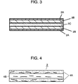
- Fig. 2 is a cross sectional view of a core of the vacuum heat insulator according to the sixth exemplary embodiment of the present invention.
- Molded body 4 is molded by laminating glass wool having an average fiber diameter of 5 ⁇ m, an average fiber length of 10 mm, and a true specific gravity of 2.5 g/cm 3 to a predetermined shape.
- Binding agent 5 is prepared by dissolving water glass of 10 wt % in water of 90 wt %. The water solution of water glass having the same weight as that of glass wool is used. The water solution of water glass is sprayed onto both surfaces of molded body 4 by means of a spray device, and then is pressed in a hot blast circulating furnace at 450°C for 20 minutes. Thus core 2 having a thickness of 15 mm and a density of 235 kg/m 3 is obtained. Core 2 has a thermal conductivity of 0.35 W/mK.
- a central layer of core 2 fabricated in the above manner is small in content of binding agent 5, and a large quantity of binding agent 5 is cured nearer to a surface layer to form a hardened layer on the surface.
- the core has a surface hardness of 65. In observing an appearance of the surface of core 2 with an optical microscope, fibers crossing one another are bound and cured by the binding agent as shown in Fig. 5.
- Hardness is defined by a value obtained when hardness of a surface of a core is measured by a durometer, and it is meant that the larger the value the harder and the smaller the value the softer.
- Vacuum heat insulator 1 is fabricated in the following manner. First, core 2 is dried in a drying furnace at 140°C for one hour. Thereafter, core 2 is inserted into exterior covering 3. An interior of the exterior covering is reduced in pressure up to 3 Pa and sealed.
- the thermal conductivity of vacuum heat insulator 1 is 0.0022 W/mK at an average temperature 24°C.
- the surface hardness is 70.
- the thermal conductivity under conditions of passage of 10 years is 0.0050 W/mK at an average temperature 24°C.
- core 2 has a surface hardness of 60.
- Vacuum heat insulator 1 according to a seventh exemplary embodiment is the same in fundamental constitution as that of the sixth exemplary embodiment. This embodiment is different from the sixth exemplary embodiment in a binding agent for a core and a molding method.
- Binding agent 5 used for a core according to this embodiment is prepared by dissolving a boric acid of 3 wt % in water of 97 wt %.
- the water solution of boric acid having the same weight as that of glass wool is used.
- the water solution of boric acid is sprayed onto both surfaces of a molded body 4 by means of a spray device, and then is once pressed at a room temperature of around 25°C. Subsequently, it is pressed in a hot blast circulating furnace at 350°C for 20 minutes, and thus a core 2 having a thickness of 15 mm, a density of 200 kg/m 3 , a thermal conductivity of 0.34 W/mK is obtained.
- a central layer of core 2 is also bound by a slight quantity of binding agent 5, and the binding agent is increased in quantity toward a surface layer. That is, the core according to this embodiment is also formed on a surface thereof with a hardened layer. Core 2 has a surface hardness of 45.
- Vacuum heat insulator 1 making use of such core 2 has a thermal conductivity of 0.0020 W/mK at an average temperature 24°C, a thickness of 14 mm with 1 mm compressed, and a density of 214 kg/m 3 .
- the surface hardness is 60.
- the vacuum heat insulator is disassembled and a weight of the core is measured, from results of which a density may be calculated.
- the thermal conductivity under conditions of passage of 10 years is 0.012 W/mK at an average temperature 24°C.
- core 2 has a surface hardness of 35.
- the binding agent includes a boric acid and pressing at room temperature is performed prior to heating compression, so that the binding agent remains also in the inside of the core and is cured inside the surface layer without generation of migration. Therefore, an interior of the core is enhanced in stiffness and as a whole in strength.
- laminated fibers coated with the binding agent prior to heating compression are compressed at a lower temperature than 100°C. Compression at room temperature in which moisture is hard to evaporate, is more preferable.
- heating compression is performed at temperature of 100°C or higher, which aims at evaporation of moisture and curing of the binding agent, so heating at a higher temperature than the curing temperature of the binding agent is desirable. 600°C or lower is preferable from the viewpoint of preventing the binding agent from permeating into the laminate excessively and fusion of fibers at the time of heating compression.
- fibers coated with a binding agent at the time of fiberization are used to fabricate a molded body, a plate-shaped body having a uniform distribution of the binding agent in the molded body is easily obtained and so it is difficult to obtain a molded body having a concentration gradient.
- fibers are laminated in a predetermined configuration and a binding agent is coated on at least one surface of the laminated fibers.
- the laminated fibers are once compressed at a lower temperature than 100°C, that is, a temperature lower than or equal to the evaporating temperature of moisture.
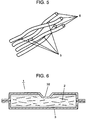
- FIG. 3 is a cross sectional view showing a core of a vacuum heat insulator according to this embodiment.
- core 2 is divided into front and back surface layers of 1 mm in a through-thickness direction to provide skin layers 2A, and a remaining inner layer of the core is divided into three layers, that is, two outer layers to constitute intermediate layers 2B, and an innermost layer to constitute central layer 2C.
- Samples having a weight of 1 g are collected from skin layers 2A, intermediate layers 2B, and central layer 2C to be torn to small pieces, and pure water of 100 ml is added to the respective samples of 1 g, shaken lightly, and mixed.
- the binding agent is eluted by ultrasonic bath for 15 minutes and its effluent is filtered.
- a quantity of boron eluted in the filtrate is found by ICP emission spectroscopic analysis method. Table 1 indicates the results.
- An eluted quantity per each sample of 1 g is 3190 ⁇ g for skin layers 2A, 2050 ⁇ g for intermediate layers 2B, and 995 ⁇ g for central layer 2C.
- the binding agent is contained in ratios per each layer of 1g such that 28.5 % of the total quantity of the binding agent is contained in skin layer 2A, 17.7 % is contained in intermediate layer 2B, 7.7 % is contained in central layer 2C, 17.7 % is contained in intermediate layer 2B on the opposite side, and 28.5 % is contained in skin layer 2A on a front side thereof.
- Analytical value of quantity of boron ( ⁇ g/g) Correction value of quantity of boron ( ⁇ g/g) Concentration distribution of boric acid (%) Skin layer 2A (upper side) 3190 3013 28.5 Intermediate layer 2B (upper side) 2050 1873 17.7 Central layer 2C 995 818 7.6 Intermediate layer 2B (lower side) 2050 1873 17.7 Skin layer 2A (lower side) 3190 3013 28.5 Glass wool 4 182 - -
- concentration distribution of the binding agent are exemplary, the values are preferably varied in a through-thickness direction, and the surface layers of the core are more preferably larger in concentration of the binding agent than an interior thereof.
- skin layers 2A be preferably larger in concentration of the binding agent than central layer 2C
- intermediate layer 2B be preferably larger in concentration of the binding agent than skin layers 2A
- intermediate layer 2B be preferably smaller in concentration of the binding agent than central layer 2C.
- Ratios, in which the core is divided, are not specifically prescribed.
- the above analytical method is exemplary, and provided that distribution of quantities of the binding agent is found, the analytical method is not specifically prescribed. It is enough to find that the binding agent is varied in concentration when visually seeing a cross section of a core.
- Vacuum heat insulator 1 is the same in fundamental constitution as that of the seventh exemplary embodiment.
- a core includes plate-shaped molded bodies of multi-layered structure.
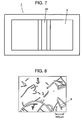
- Fig. 4 is a cross sectional view of a core of a vacuum heat insulator according to this embodiment.
- core 2 includes three plate-shaped molded bodies (referred below to as molded bodies) 4A, 4B having substantially the same thickness.
- Two molded bodies 4A include glass wool which has an average fiber diameter of 5 ⁇ m, an average fiber length of 10 mm, and a true specific gravity of 2.5 g/cm 3 , and are formed by laminating to predetermined shapes, and a binding agent is added to the molded bodies.
- the binding agent is prepared by dissolving a boric acid of 5 wt % in water of 95 wt %.
- the water solution of boric acid having the same weight as that of glass wool is used.
- the water solution of boric acid is sprayed onto both surfaces of the molded bodies by means of a spray device, and then is pressed at room temperature. They are pressed in a hot blast circulating furnace at 350°C for 20 minutes, and molded bodies 4A having a thickness of 5 mm and a density of 230 kg/m 3 are obtained.
- Another molded body 4B is formed by subjecting glass wool which has an average fiber diameter of 5 ⁇ m and an average fiber length of 10 mm, to compressing and heating at 350°C without the use of a binding agent, and has a thickness of 5 mm and a density of 220 kg/m 3 .
- Three plate-shaped molded bodies 4A, 4B are used to be overlapped such that molded bodies 4A with a boric acid are disposed outside and molded body 4B with only glass wool is disposed inside, thus providing core 2.
- Molded body 4A is disposed on the surface is a cured layer. Its surface hardness is 45.
- Entire core 2 has a density of 190 kg/m 3 and a thermal conductivity of 0.34 W/mK.
- Vacuum heat insulator 1 with such core 2 has a thermal conductivity of 0.0019 W/mK at an average temperature 24°C and a surface hardness of 60.
- the thermal conductivity under conditions of passage of 10 years is 0.014 W/mK at an average temperature 24°C.
- core 2 has a surface hardness of 35.
- the plate-shaped molded bodies with a boric acid binding agent are provided for the surface layers and the plate-shaped molded body with only glass wool is provided for the central layer, a core having a small solid thermal conductivity and an excellent adiabatic performance is obtained because of absence of a binding agent in the central layer.
- a comparative example is the same in fundamental constitution as that of the sixth exemplary embodiment.
- a core is prepared by spraying a binding agent on fiber surfaces of glass wool which has an average fiber diameter of 5 ⁇ m after fiberization, so that the binding agent evenly adheres the surfaces.
- the binding agent is prepared by dissolving a phenol resin of 10 wt % in water of 90 wt %.
- a water solution of phenol resin having the same weight as that of glass wool is used.
- the raw stock with the binding agent is laminated to a predetermined density, and pressed in a hot blast circulating furnace at 200°C for 20 minutes in a manner to have a density of 200 kg/m 3 .
- the core fabricated in this manner is dried in a drying furnace at 140°C for one hour, and inserted into an exterior covering, and an interior of the exterior covering is reduced in pressure to 3 Pa and sealed.
- the vacuum heat insulator of the above comparative example has a thermal conductivity of 0.0040 W/mK at an average temperature 24°C.
- the thermal conductivity under conditions of passage of 10 years is 0.021 W/mK at an average temperature 24°C. Since a phenol resin is used for the binding agent and evenly cured in the core, both the initial capacity and the capacity with passage of time are degraded as compared with the sixth exemplary embodiment.
- the binding agent is evenly cured, the initial performance is degraded and a long period of time for exhaustion at the time of fabrication of the vacuum heat insulator is needed as compared with the seventh exemplary embodiment.
- the core In molding a core by the use of fibers such as glass wool, etc. and a binding agent, the core has a large solid thermal conductivity when the binding agent is dispersed throughout the glass wool to put individual fibers in a bound state over an interior of the fiber molded body.
- portions in which the binding agent is small in concentration are provided according to the sixth to eighth exemplary embodiments, whereby the solid thermal conductivity becomes small and the adiabatic performance is improved.
- the portions in which the binding agent is small in concentration are decreased in resistance to exhaustion, so that a period of time required for evacuation is shortened and the vacuum heat insulator is enhanced in productivity.
- the surface layers are preferably larger in concentration of the binding agent than the inner layer in a through-thickness direction of the core. That is, it is preferable to form cured layers on the surfaces.
- the construction in addition to the above effect, it is possible to obtain a core having an excellent surface flatness and a vacuum heat insulator being excellent in outward appearance.
- core 2 may include a board made of organic or inorganic fibers, a board formed by solidification of powder, etc. and is not specifically limitative.
- a core including a board made of a fibrous material can use a known material such as inorganic fibers, or organic fibers including natural fibers such as cotton, etc. and synthetic fibers such as polyester, nylon, aramid, etc as described in the first exemplary embodiment.
- a core including a board formed by solidification of powder can use inorganic powder such as silica, pearlite, carbon black, etc.
- inorganic powder such as silica, pearlite, carbon black, etc.
- known materials are usable as by solidifying organic powder such as powder of synthetic resins, etc. by means of a fiber binding agent, or inorganic or organic liquid binding agent.
- a fibrous material for a core is preferable.
- Use of a fibrous material makes it possible to obtain a vacuum heat insulator which is easy to mold, small in solid thermal conductivity, that is, has excellent in moldability and adiabatic property.
- a fibrous material for a core on surfaces of which a binding agent is high in concentration and cured layers are provided.
- cured layers may be formed only on surface layers of a molded body and almost a small quantity of binding agent having permeated inside is moved to the surface layers due to migration to form little cured layers inside. In this case, it is feared that crack is generated inside and an entire molded body is decreased in strength.
- a plate-shaped molded body by forming fibers into a plate shape, thereafter coating a binding agent on surfaces thereof, and subjecting the formed fiber to compressing and heating.
- layers having a high concentration owing to curing of the coated binding agent are formed on the surface layers.
- a small quantity of binding agent permeated inside does not migrate so much but is cured inside the surface layers. Consequently, it is possible to obtain a molded body in which the binding agent is varied in concentration in a through-thickness direction and a small quantity of binding agent is cured inside, and which is excellent in strength.
- Inorganic fibers are desirable in terms of heat resistance at the time of compressing and heating. Especially, glass wool and glass fiber are preferable because of a high weather resistance and a favorable water resistance. In particular, inorganic fibers made of boron containing glass are desirable because of excellent weather resistance and water resistance.
- the fibers are not specifically limited in fiber diameter.
- the fiber diameter desirably ranges from 0.1 to 20 ⁇ m, preferably from 1 to 10 ⁇ m, and further preferably from 2 to 7 ⁇ m.
- fibers having an average fiber length of 5 to 15 mm are preferably used from the viewpoint of preventing peel of the laminate but not limitative.
- Non-woven web may be used in the same manner as in the first exemplary embodiment.
- the powder described above may be added to a fibrous material for a core.
- a fibrous material for a core Known materials such as pulverized pieces of a foam resin such as urethane foam, phenol foam, styrene foam, etc. may be used appropriately.
- Inorganic or organic binding agents described with respect to the second to fourth exemplary embodiment are usable as a binding agent.
- organic binding agents formed of thermoplastic resins such as vinyl acetate, acrylic resins, etc., or natural adhesives, etc. will do. It is also possible to mix these materials for use, or to dilute them with water or a known organic solvent for use.
- the binding agent preferably contains at least one of boric acid, borate, or phosphoric acid, phosphate, or heated products thereof. Some ones of these substance themselves form a glassy substance and have a good affinity for glass fibers to be hard to migrate.
- a method of adhering a binding agent to a core material includes adhering by coating or spraying a binding agent or its diluted solution. Concretely, a binding agent is sprayed after a core material is molded to some extent, and thereafter compressing and heating is performed, thereby enabling obtaining a molded body, in which the binding agent is varied in concentration in a through-thickness direction of the plate-shaped molded body.
- a binding agent or its diluted solution is sprayed at the time of fiberization.
- Fibers in which a binding agent is large in concentration are arranged in certain portions of a plate-shaped molded body, and fibers, in which a binding agent is small in concentration or a binding agent is absent, are arranged in the remaining portions.
- a fiber laminated body is solidified by compressing and heating or the like.
- a core varied in concentration in a through-thickness direction is also obtained by combining two or more of a plate-shaped molded body, in which a binding agent is large in concentration, and a plate-shaped molded body, in which a binding agent is small in concentration.
- a binding agent adhering in a manner that the agent has a concentration in which a solid of the binding agent is at least 0.1 wt % but at most 20 wt % relative to the binding agent. This is because as a binding agent is increased in quantity, an increase in gases generated from the binding agent and an increase in solid thermal conductivity are feared to have adverse influences on the adiabatic performance of a vacuum heat insulator. On the other hand, a fiber laminated body is insufficiently solidified when a binding agent is small in quantity.
- a binding agent is different in concentration at least between certain portions and other certain portions in a through-thickness direction of a core. It aims at producing an effect that those portions in which a binding agent is small in concentration are decreased in solid thermal conductivity and resistance to exhaustion, and those portions in which a binding agent is large in concentration are given stiffness of a board.
- those portions in which a binding agent is large in concentration preferably define at least one surface layer of a core or both surface layers. This is because a finished vacuum heat insulator is excellent in strength and favorable in surface flatness.
- a core be molded to have a density of 100 kg/m 3 to 400 kg/m 3 , and density may be varied inside.
- a core more preferably has a density of from 120 to 300 kg/m 3 and further preferably from 150 to 250 kg/m 3 . The reason for this is the same as in the fifth exemplary embodiment.
- Core 2 preferably has a surface hardness of 15 to 70 and desirably preferably a surface hardness in the range of 20 to 40. With the surface hardness of 15 or more, it is possible to ensure a handling quality and surface flatness. On the other hand, with the surface hardness of 70 or less, waste disposal of heat insulators is facilitated after refrigerators are discharged.
- the surface hardness corresponds to that of core 2 prior to packaging with exterior covering 3. Accordingly, a vacuum heat insulator after packaging with exterior covering 3 preferably has a surface hardness of 50 to 80 and desirably a surface hardness in the range of 60 to 75.
- the surface hardness manifests owing to formation of a cured layer on surfaces of core 2, and fibers or powder particles in the cured layer are thermally fixed by a binding agent. That is, fibers or powder particles are bound by the binding agent to thereby achieve formation of the cured layer.
- the cured layer is small in void ratio and formed by binding of fibers or powder with the binding agent whereby it is high in stiffness. Accordingly, by forming such cured layer at least on one surface of core 2, preferably on both surfaces thereof, core 2 is enhanced in stiffness and made favorable in handling quality.
- core 2 is increased in hardness, depression or large irregularities are little generated on the surfaces of heat insulator 1 and flatness on the surfaces can be maintained even after the core is surrounded by exterior covering 3 and an interior of the exterior covering is reduced in pressure and sealed. Therefore, adhesiveness at the time of mounting to refrigerating/cooling equipment is improved and the adiabatic effect is made further favorable.
- the vacuum heat insulator 1 according to the sixth to eighth exemplary embodiments is lightweight, high in stiffness and planar accuracy because it contains therein a small quantity of binding agent, so one having a large area is usable.
- concentration of the water solution of the binding agent cannot be unconditionally prescribed but is desirably 0.5 to 20 wt % in view of solubility in water.
- An application quantity of a water-diluted solution of the binding agent is not specifically prescribed but is preferably at least half but at most 3 times the fibrous material in weight ratio. This is because with less than half, the water solution is hard to permeate inside the laminated fibers, and with more than 3 times, surplus water content in a liquid state outflows in the subsequent heating and compressing process, and the binding agent also outflows along therewith to cause loss in the binding agent.
- a vacuum heat insulator according to a ninth exemplary embodiment is the same in fundamental constitution as that of the sixth exemplary embodiment.
- a cured layer is formed by spraying water on surfaces of a core.
- a raw stock of glass fibers manufactured by the centrifuge method and having an average fiber diameter of about 4 ⁇ m to 6 ⁇ m is cut to a predetermined size and aggregated in a predetermined amount to be laminated.
- Ion exchanged water around a neutrality of a PH value of at least 6 but at most 8 is sprayed onto surfaces of a fiber laminate in a manner to adhere evenly thereto.
- a sprayed quantity is made 1.5 to 2.0 times in a weight of the fiber laminate.
- the fiber laminate onto which the ion exchanged water is sprayed is compressed at room temperature around 25°C to make the water diffused and permeated inside the fiber laminate.
- the fiber laminate is subjected to high-temperature compression in a heating press to be held for 10 minutes or longer to be dried, thus fabricating molded body 5 having a thickness of 10 mm.
- the laminate is placed in a metallic jig heated to 380°C and is pressed from above by a metallic presser plate.
- the molded body thus obtained is hard to be split in a direction of lamination and made high in reliability because glass fibers are oriented perpendicular to a direction of heat transmission by repeated compression.
- a molded body fabricated to have a thickness of 10 mm is cut to 180 mm ⁇ 180 mm sized pieces to form core 2.
- Core 2 is dried in a drying furnace at 150°C for about 60 minutes and water moisture remaining after molding is removed.
- Dried core 2 is taken out from the drying furnace, an adsorbent is quickly received into recesses, which have been beforehand formed in core 2, and core 2 receiving therein the adsorbent is inserted into exterior covering 3 to be placed in a vacuum chamber.
- An interior of the vacuum chamber is reduced in pressure and exhausted to have a degree of vacuum of at most 1.33 Pa, in which state an opening of exterior covering 3 is thermally fused in the vacuum chamber to be sealed.
- a vacuum heat insulator 1 is obtained.
- a cured layer of core 2 thus structured is formed by simply spraying water on the surfaces of the laminate. That is, fibers are bound by that substance which is eluted from the fibers due to adhesion of water. The substance thus eluted from the fibers functions as a binding agent. With the method with water spraying, water does not completely permeate an inner layer and the inner layer becomes weak in binding strength, so that it is possible to obtain a core in which the inner a layer the softer the layer.
- ion exchanged water is used as water being sprayed onto the fiber laminate, it is not specifically limitative but distilled water, alkali ion water, mineral water, filtered pure water, or city water will also be used.
- ion exchanged water is preferable in terms of adiabatic performance.
- An adsorbent is received if desired and may not be used especially.
- the thermal conductivity of vacuum heat insulator 1 obtained in this manner is measured at an average temperature 24°C to be 0.0020 W/mK. In a test for reliability with passage of time corresponding to 10 years, a value of thermal conductivity is 0.025 W/mK and so deterioration is slight.
- the density of core 2 is found by measuring weight and volume of vacuum heat insulator 1, unsealing exterior covering 3 of vacuum heat insulator 1, and measuring weight and volume of exterior covering 3 and the adsorbent to subtract the same from the values of vacuum heat insulator 1.
- the density of core 2, according to this embodiment, thus found is 250 kg/m 3 .
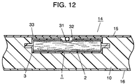
- Fig. 6 is a cross sectional view of a vacuum heat insulator according to a tenth exemplary embodiment of the present invention.
- Fig. 7 is a plan view of the vacuum heat insulator according to the tenth exemplary embodiment of the present invention.
- vacuum heat insulator 1 according to this embodiment is formed on a surface thereof with groove 4.
- vacuum heat insulator 1 a method of manufacturing vacuum heat insulator 1 will be described.
- a plate-shaped vacuum heat insulator is fabricated in the same manner as in the exemplary embodiment.
- the thermal conductivity of such vacuum heat insulator is 0.0023 W/mK at an average temperature 24°C.
- the vacuum heat insulator is pressingly narrowed in press molding with the use of a molding die to be formed on a surface thereof with groove 32, dimensions of which are 50 mm at an opening, 20 mm at a bottom surface (straight portion), and 5 mm in depth. Corner portions of the molding die in pressure contact with exterior covering 3 assume a cylindrical shape.
- Groove 32 thus formed suffers no damage such as pin holes or the like to the surface of exterior covering 3 and the thermal conductivity is not varied except groove 32.
- the thermal conductivity under conditions of passage of 10 years is 0.0055 W/mK at an average temperature 24°C, and there is no difference between the vacuum heat insulator and a vacuum heat insulator formed with no groove.
- groove 32 since a binder in the inner layer of core 2 is small in concentration and the inner portion is soft, there is caused no problem in forming groove 32 by means of press molding after fabrication of the vacuum heat insulator.
- Groove 32 can be molded at a relatively small pressure of pressing in the atmosphere with the use of a common apparatus. Groove 32 is in some cases necessary to keep out of other constituent elements when an adiabatic box, to which vacuum heat insulator 1 is applied, is to be formed. Groove 32 is readily formed on vacuum heat insulator 1 according to the invention to lead to an improvement in productivity and reduction on cost.
- Vacuum heat insulator 1 according to this embodiment is fabricated in the same manner as in the sixth to eighth exemplary embodiments after a groove is formed on a core fabricated in the sixth to eighth exemplary embodiments by means of cutting. In this stage, vacuum heat insulator 1 having been formed with groove 32 is resulted.
- the thermal conductivity of vacuum heat insulator 1 is the same as that in the exemplary embodiment and the thermal conductivity under conditions of passage of 10 years also has no difference therebetween.
- a binder in the inner layer of the core is small in concentration and the inner portion is soft, the groove is readily formed on the molded body and there is no fear of damage to the exterior covering possibly caused by a molding die.
- the groove may be formed by that molding die, which is used in heating and compressing molded body 5.
- a vacuum heat insulator according to a twelfth exemplary embodiment is the same in fundamental constitution and materials as those of the ninth exemplary embodiment.
- a groove is formed on a surface of such vacuum heat insulator. While the method is the same as that in the tenth exemplary embodiment, a molded body obtained in case of using water is softer than that in case of using a binder, and damage to a exterior covering is small.
- a vacuum heat insulator according to a thirteenth exemplary embodiment is the same in fundamental cross sectional structure as that of the first exemplary embodiment shown in Fig. 1.
- Core 2 is different in constitution from that in the first exemplary embodiment.
- Core 2 is a plate-shaped molded body composed of a glass wool board formed by hot pressure forming in a dry process by means of a binding agent. Core 2 contains fibers having short fiber lengths.
- Table 1 indicates results of structuring vacuum heat insulator 1 by the use of core samples A to D having different fiber lengths and different ratios of content of fibers and evaluating them in terms of thermal conductivity. Compressibility indicated in Table 2 is found from a ratio of that thickness of core 2 after structuring of a vacuum heat insulator which is found from a thickness of vacuum heat insulator 1, and a thickness of core 2 prior to structuring of the vacuum heat insulator.
- Fig. 8 shows a state in which vacuum heat insulator 1 making use of the sample C is unsealed and core 2 is taken out for observation.
- an optical microscope is used under the condition of standard temperature and pressure to make observation in photographic magnification of 200 (objective lens magnification; ⁇ 50).
- object lens magnification ⁇ 50
- fibers are oriented perpendicular to a direction of heat transmission.
- Table 2 indicates results of measuring fiber lengths of total fibers present in a range of observation and counting the number of fibers assuming that fibers beyond the range have a fiber length of at least 100 ⁇ m.
- Table 2 also indicates results of adjusting data and calculating the number of fibers having a fiber length of 100 ⁇ m or smaller.
- vacuum heat insulator 1 possesses a low initial thermal conductivity. That is, the vacuum heat insulator is excellent in adiabatic performance. In the case where fibers having a fiber length of 100 ⁇ m or smaller are included in the range of less than 40 % as in the sample D, heat transmission through fibers is much so the vacuum heat insulator provide a high thermal conductivity.
- a getter substance such as a gas adsorbent, a moisture adsorbent, etc. may be incorporated into vacuum heat insulator 1.
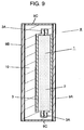
- Fig. 9 is a cross sectional view of an adiabatic element according to a fourteenth exemplary embodiment of the present invention.
- Adiabatic element 8 according to this embodiment includes vacuum heat insulator 1 according to any one of the first to ninth exemplary embodiments.
- the vacuum heat insulator according to the thirteenth exemplary embodiment may be used.
- Vacuum heat insulator 1 is arranged in a space enclosed by plate elements 9A, 9B as an exterior covering and frame 9C connecting outer peripheries of plate elements 9A, 9B together in such a manner that one flat surface of vacuum heat insulator 1 contacts closely with plate element 9A.
- Foamy heat insulator 10 as a heat insulator other than the vacuum heat insulator is filled in a space except vacuum heat insulator 1.
- Vacuum heat insulator 1 and adiabatic element 8 are in the form of a plate.
- Foamy heat insulator 10 is, for example, rigid urethane foam. It may be phenol foam, st
- Plate elements 9A, 9B and frame 9C are made of metals and rigid resins, and all of them may be made of the same material, or one of plate elements 9A, 9B may be made of metal and the other may be made of a resin.
- Frame 9C may be formed integral with plate element 9A or plate element 9B.
- only one flat surface of vacuum heat insulator 1 is made in close contact with plate element 9A but the other flat surface of vacuum heat insulator 1 may also be made in close contact with plate element 9B.
- that surface of plate element 9A or 9B, which is made in close contact with the flat surface of vacuum heat insulator 1, is high in flatness.
- polystyrene foam may be used as a heat insulator other than the vacuum heat insulator.
- plate elements 9A, 9B, frame 9C, and foamy heat insulator 10 protect vacuum heat insulator 1 from damage caused by external forces and maintain a low pressure state inside vacuum heat insulator 1. Therefore, the adiabatic performance of vacuum heat insulator 1 is maintained over a long term, and hence the adiabatic performance of adiabatic element 8 is maintained over a long term. Since fillet-shaped fused portions 3A of exterior covering 3 of vacuum heat insulator 1 are hidden, protected, and fixed, handling becomes easy to enlarge a range in which vacuum heat insulator 1 is applied. Since vacuum heat insulator 1 has a high adiabatic performance and the core has a great mechanical strength, it is possible to decrease a thickness of vacuum heat insulator 1 and hence a thickness of adiabatic element 8.
- foamy heat insulator 10 is filled in that portion of the space enclosed by plate elements 9A, 9B and frame 9C serving as an exterior covering, which is not occupied by vacuum heat insulator 1. Thereby, it is easy to fill a space between the exterior coverings and vacuum heat insulator 1 with foamy heat insulator 10 owing to flowability thereof at the time of filling.
- Thin vacuum heat insulator 1 is usable also in case of arranging foamy heat insulator 10 between one surface of vacuum heat insulator 1 and the exterior covering.
- a gap for filling of foamy heat insulator 10 is ensured between one surface of vacuum heat insulator 1 and plate element 9A to such an extent that flowability (filling quality) of foamy heat insulator 10 is not hindered, whereby adiabatic element 8 having an excellent adiabatic property is provided.
- a foaming agent used in foaming foamy heat insulator 10 such as rigid urethane foam is not specifically limitative.
- the foaming agent desirably includes cyclopentane, isopentane, n-pentane, isobutane, n-butane, water (foaming of carbon dioxide), azo compounds, argon, etc.
- cyclopentane is desirable in terms of adiabatic performance.
- Fig. 10 is a cross sectional view of a storage shed according to a fifteenth exemplary embodiment of the present invention.
- the storage shed according to this embodiment has outer box 11, partition plate 12, inner box 13, and adiabatic element 8.
- Outer box 11 defines an outer shell of the storage shed itself.
- Partition plate 12 compartments an interior of outer box 11 into an upper storage room and a lower machine room.
- Inner box 13 is arranged apart from inner surfaces of outer box 11 and an upper surface of partition plate 12 with predetermined spaces, and inner box 13 defines inner wall surfaces of the storage room.
- All outer box 11, partition plate 12, and inner box 13 are made of metal or a rigid resin.
- Adiabatic elements 8A, 8B are arranged as heat insulating plates between outer box 11 and inner box 13 and between partition plate 12 and inner box 13.
- Adiabatic element 8C serves as an adiabatic partition to compartment the storage room into two rooms of different temperatures.
- Adiabatic elements 8A to 8C are the same in structure as adiabatic element 8 in the fourteenth exemplary embodiment.
- an exterior covering of adiabatic element 8C is preferably made of a metal having a relatively high mechanical strength so as to eliminate the need of providing a protective member for surface protection.
- adiabatic elements 8 according to the fourteenth embodiment are combined to form adiabatic walls for heat insulation of an interior of the storage shed.
- a storage shed in which the adiabatic walls are high in mechanical strength and excellent in adiabatic property.
- the adiabatic walls are decreased in thickness to provide a storage shed increased in inner volume or decreased in outside dimensions.
- adiabatic elements 8 serve as an adiabatic partition plate to compartment the interior of the storage shed into a plurality of rooms at different temperatures. Thereby, a quantity of heat transmitted between the rooms compartmented by adiabatic element 8C is decreased. Alternatively, adiabatic element 8C is decreased in thickness to increase inner volumes of the storage rooms. Alternatively, the storage shed is decreased in outside dimensions.
- the storage shed according to this embodiment is applicable to automatic vending machines and cold showcases. While adiabatic element 8C shown in Fig. 10 divides the storage room laterally into two sections, the storage room may be divided into two or more sections, or divided vertically.
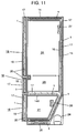
- Fig. 11 is a cross sectional view of an adiabatic box, adiabatic doors, a storage shed, and a refrigerator composed of them, according to a sixteenth exemplary embodiment of the present invention.
- Adiabatic box 14 has vacuum heat insulator 1 according to any one of the first to ninth and thirteenth exemplary embodiments.
- Vacuum heat insulators 1 are arranged in a space surrounded by outer box 15 and inner box 16 as exterior coverings. Each one of surfaces of vacuum heat insulators 1 is arranged in a manner to contact closely with outer box 15 or inner box 16 which defines a bottom surface of adiabatic partition wall 14A.
- Outer box 15 and inner box 16 are made of metal or synthetic resins.
- Vacuum heat insulators 1 are plate-shaped. Foamy heat insulator 17 other than the vacuum heat insulator is filled in a space except vacuum heat insulators 1.
- foamy heat insulator 17 is made of, for example, rigid urethane foam.
- adiabatic box 14 is of dual-layered structure to include vacuum heat insulators 1 and foamy heat insulator 17, and in the form of a box.
- vacuum heat insulators 1 are beforehand bonded and fixed to outer box 15, and inner box 16 which defines the bottom surface of adiabatic partition wall 14A, and a raw material of foamy heat insulator 17 is injected to be foamed integrally.
- Vacuum heat insulators 1 are arranged substantially evenly on respective surfaces, that is, both side surfaces, a roof surface, a back surface, and a bottom surface of adiabatic box 14 to occupy 80 % of a surface area of outer box 15.
- adiabatic box 14 With adiabatic box 14 according to this embodiment, outer box 15, inner box 16, and foamy heat insulator 10 protect vacuum heat insulators 1 from damage due to external forces. Accordingly, a low pressure state inside vacuum heat insulators 1 is kept, so that the adiabatic performance of vacuum heat insulators 1 is maintained over a long term. Therefore, the adiabatic performance of adiabatic box 14 is maintained over a long term. Since vacuumheat insulators 1 are high in adiabatic performance and cores thereof are high in mechanical strength, vacuum heat insulators 1 can be made small in thickness and hence walls defining adiabatic box 14 become small in thickness.
- adiabatic box 14 With adiabatic box 14 according to this embodiment, foamy heat insulator 17 is filled in the space except vacuum heat insulators 1. Therefore, it is easy to fill a space between exterior coverings and vacuum heat insulators 1 with foamy heat insulator 17 owing to flowability thereof at the time of filling. Thin vacuum heat insulator 1 is usable also in case of arranging foamy heat insulator 17 between one surface of vacuum heat insulator 1 and the exterior covering. Therefore, a gap for filling of foamy heat insulator 17 can be ensured between one surface of vacuum heat insulator 1 and outer box 15, or inner box 16 which defines the bottom surface of adiabatic partition wall 14A, to such an extent that flowability (filling quality) of foamy heat insulator 17 is not hindered. Thus adiabatic box 14 having an excellent adiabatic property is provided.
- adiabatic box 14 When adiabatic box 14 is structured to have the same thickness as that in the conventional one, adiabatic box 14 is superior in adiabatic property to that in the conventional one and, in the case where adiabatic box 14 is made the same in adiabatic property as that in the conventional one, walls defining adiabatic box 14 are decreased in thickness as compared with that in the conventional one.
- Adiabatic box 14 is structured integral with adiabatic partition wall 14A.
- adiabatic partition wall 14A may be made separately in the form of a plate like the adiabatic element according to the fourteenth exemplary embodiment and incorporated into adiabatic box 14.
- Each of adiabatic doors 18 has vacuum heat insulator 1 according to any one of the first to ninth and thirteenth exemplary embodiments.
- Vacuum heat insulator 1 is arranged in a space surrounded by outside surface plate 19 and inside surface plate 20 as exterior coverings. Outside surface plate 19 and inside surface plate 20 are made of metal or synthetic resins.
- One surface of vacuum heat insulator 1 is arranged in a manner to contact closely with outside surface plate 19.
- Foamy heat insulator 17 other than the vacuum heat insulator is filled in a space except vacuum heat insulator 1.
- Each of adiabatic door 18 is of dual-layered structure composed of vacuum heat insulator 1 and foamy heat insulator 17, and plate-shaped to close a front opening of adiabatic box 14 in an openable and closable manner.
- vacuum heat insulator 1 is beforehand bonded and fixed to the outside surface plate 19, and a raw material of foamy heat insulator 17 is injected to be foamed integrally.
- adiabatic door 18 With adiabatic door 18 according to this embodiment, outside surface plate 19, inside surface plate 20, and foamy heat insulator 17 protect vacuum heat insulator 1 from damage due to external forces. Foamy heat insulator 17 is filled in a space except vacuum heat insulator 1. Thus in the same manner as with the adiabatic box described above, a thin vacuum heat insulator having an excellent adiabatic property, which is maintained over a long term, is obtained and adiabatic doors 18 having the same properties are provided.
- the storage shed includes adiabatic box 14, adiabatic doors 18, and the storage rooms formed in a space surrounded by adiabatic box 14 and adiabatic doors 18.
- Vacuum heat insulators 1 are used for both adiabatic box 14 and adiabatic doors 18 to enhance the adiabatic property of adiabatic box 14 and adiabatic doors 18.
- the storage room is increased in inner volume by making adiabatic box 14 and adiabatic door 18 small in thickness.
- the storage room is decreased in outside dimensions.
- the refrigerator has adiabatic box 14, adiabatic doors 18, the storage rooms, and a cooling device.
- the storage rooms are formed in a space surrounded by adiabatic box 14 and adiabatic doors 18 to include freezing room 21 at -15°C to -25°C in a lower stage, cold storage room 22 at 0°C to 10°C in an upper stage, and vegetable room 23 at 0°C to 10°C in a middle stage.
- the cooling device cools freezing room 21, cold storage room 22, and vegetable room 23.
- the cooling device includes compressor 24, condenser 25, freezing room cooler (referred below to as cooler) 26, and cold storage room cooler (referred below to as cooler) 27.
- Compressor 24 is arranged on a back surface side of a machine room formed at a bottom of adiabatic box 14. Condenser 25 is positioned below freezing room 21 within the machine room. Cooler 26 is arranged on a back surface of freezing room 21. Cooler 27 is arranged on a back surface of cold storage room 22. Adiabatic partition wall 14A is arranged between freezing room 21 and cold storage room 22, which are different in storage temperature from each other. Adiabatic partition wall 14A may be provided with a notch (not shown), in which a damper (not shown) is mounted so that cooler 26 acts to cool cold storage room 22 and vegetable room 23 without the provision of cooler 27.
- Refrigerant used in the cooling device may be Freon 134a, isobutane, n-butane, propane, ammonia, carbon dioxide, and water, and is not specifically limitative.
- the refrigerator according to this embodiment has vacuum heat insulator 1 described in the first to ninth and thirteenth exemplary embodiments.
- the refrigerator thus constructed is made highly adiabatic because of a sharply excellent adiabatic performance relative to that of conventional foamy heat insulators. Accordingly, compressor 24 serving to cool an interior of the storage shed countering invasion of heat from outside is sharply reduced in operation time. That is, the cooling device serving to cool the cold storage rooms (freezing room 21, cold storage room 22, and vegetable room 23) to predetermined temperatures is reduced in operational energy to contribute to energy saving.
- the cold storage room can be increased in inner volume or reduced in outside dimensions.
- Adiabatic box 14 and adiabatic doors 18 are of dual-layered structure composed of vacuum heat insulators 1 and foamy heat insulator 17.
- the vacuum heat insulators are combined with foamy heat insulator 17 in adiabatic box 14 to thereby achieve an increase of the box in strength. Therefore, even when vacuum heat insulators 1 are positioned between outer box 15 and inner box 16 and between outside surface plate 19 and inside surface plate 20, between which foamy heat insulator 17 is filled, distortion and indentation are not generated on outer box 15, inner box 16, and outside surface plate 19. Accordingly, the adiabatic box and the adiabatic door are provided to be excellent in adiabatic performance.
- a cross sectional view of a refrigerator according to a seventeenth exemplary embodiment of the present invention is the same as Fig. 11 showing the sixteenth exemplary embodiment.
- vacuum heat insulator 1 described in the sixth to eighth exemplary embodiments is used.
- Vacuum heat insulator 1 is arranged on outer box 15 inside the box such that a surface thereof on that side, on which a cured layer of core 2 is formed, faces an inner surface of outer box 15.
- An amount of electric power consumption of the refrigerator thus constructed is decreased 25 % relative to that of a refrigerator provided with no vacuum heat insulator.
- a freezing equipment, and a cooling equipment, that is, a refrigerator, which is excellent in adiabatic performance, is obtained by arranging the vacuum heat insulators, which is excellent in adiabatic performance, according to the sixth to eighth exemplary embodiments, in a space defined by the outer box and the inner box and filling foamy heat insulator in a space except the vacuum heat insulators. Since the cured layer is formed on the surface of core 2, stiffness of the core is high. Thereby, a refrigerator of energy saving and excellent outward appearance is obtained, in which the outward appearance (planar accuracy) of outer box 15 and the adiabatic performance of the adiabatic box can be made higher-dimensionally compatible.
- a cross sectional view of a refrigerator according to an eighteenth exemplary embodiment of the present invention is the same as Fig. 11 in the sixteenth exemplary embodiment.
- the vacuum heat insulator described in the tenth to twelfth exemplary embodiments is used.
- Fig. 12 is an enlarged, crosssectionalviewofanessential part of a roof surface of a refrigerator according to this embodiment.
- vacuum heat insulator 1 formed with groove 32 capable of receiving therein refrigerant pipe 31 is arranged on that portion of an inner surface of outer box 15, where refrigerant pipe 31 is arranged, such that refrigerant pipe 31 is received in the groove 32.
- Vacuum heat insulator 1 thus formed with groove 32 is described with respect to the tenth to twelfth exemplary embodiments.
- a plurality of small vacuum heat insulators are arranged on that portion of the inner surface of outer box 15, on which refrigerant pipe 31 is arranged, keeping away from the refrigerant pipe 31.
- large vacuum heat insulator 1 can be arranged in a manner to cover refrigerant pipe 31. Therefore, a refrigerator excellent in energy saving can be obtained, in which a small number of vacuum heat insulators 1 makes it possible to efficiently prevent heat of outer box 15 and the refrigerant pipe 31 from being transmitted to an interior of the refrigerator.
- Vacuum heat insulator 1 is fixed to outer box 15 by means of thermoplastic, gelled, hot melt adhesive (referred below to as adhesive) 33.
- a layer of adhesive 33 has a thickness of about 100 ⁇ m. The thickness preferably ranges from 70 to 130 ⁇ m.
- Adhesive 33 is coated evenly on a surface of vacuum heat insulator 1 in proper quantities by means of a roller or the like. The surface is to be bonded to outer box 15.
- the provision of a layer of adhesive 33 having a thickness over 130 ⁇ m leads to waste of the adhesive and reduction in adiabatic performance because adhesive 33 transmits heat more easily than the foamy heat insulator. When the layer of adhesive 33 is less than 70 ⁇ m in thickness, reliability in adhesion is lowered.
- a hot melt adhesive is preferable in terms of reliability in adhesion.
- a type of hot melt adhesive is not specifically limitative and there are listed ones, of which a base includes ethylene-vinyl acetate copolymer resin, polyamide resin, polyester resin, synthetic rubber, etc.
- Adhesive 33 may be used for fixation of vacuum heat insulator 1 in the sixteenth and seventeenth exemplary embodiments.
- refrigerant pipe 31 is received in groove 32.
- groove 32 may be provided in a manner to receive projections.
- the vacuum heat insulator While an effect is produced when the vacuum heat insulator is applied to a location in the refrigerator according to the sixteenth to eighteenth exemplary embodiments, where is large in temperature difference between outside and inside the refrigerator, the coverage of 50 % or more relative to a surface area of the outer box is desirable. When the coverage is over 50 %, influences due to heat loss in rigid urethane foam are decreased and insulation effectiveness owing to application of the vacuum heat insulator becomes dominant, so that efficient heat insulation becomes possible.
- inorganic fibers for a core of the vacuum heat insulator. Since inorganic fibers are nonflammable, the refrigerator is enhanced in safety.
- the refrigerator according to this embodiments is shown as a typical example of equipments, which operate in the temperature zone of -30°C to room temperature, at which heat insulation is required.
- This vacuum heat insulator is also usable in, for example, insulated vans, refrigerators making use of thermoelectric refrigeration, etc.
- Cold equipments such as automatic vending machines, making use of cold and warmth in a range up to high temperatures come within the category of the present invention.
- Gas equipments, or equipments such as cooler boxes, etc., requiring no power are also included.
- vacuum heat insulator is also usable in personal computers, jar pots, rice cookers, etc.
- the vacuum heat insulator according to the present invention includes a core molded to be plate-shaped with the use of a binding agent.
- the vacuum heat insulator assumes any one of the following configurations.
- Such vacuum heat insulator is excellent in adiabatic performance.
- Adiabatic elements, adiabatic doors, adiabatic boxes, storage sheds, and refrigerators, in which such vacuum heat insulator and a foamy heat insulator are used have an excellent adiabatic property, and maintain the adiabatic property over a long term, so that they can be made thin and small in size. Alternatively, it is possible to increase an inner volume.
- the refrigerators are excellent in adiabatic property to contribute to energy saving.
Landscapes
- Engineering & Computer Science (AREA)
- General Engineering & Computer Science (AREA)
- Mechanical Engineering (AREA)
- Chemical & Material Sciences (AREA)
- Combustion & Propulsion (AREA)
- Physics & Mathematics (AREA)
- Thermal Sciences (AREA)
- Thermal Insulation (AREA)
Abstract
Description
| Analytical value of quantity of boron (µg/g) | Correction value of quantity of boron (µg/g) | Concentration distribution of boric acid (%) | |
| | 3190 | 3013 | 28.5 |
| | 2050 | 1873 | 17.7 |
| | 995 | 818 | 7.6 |
| | 2050 | 1873 | 17.7 |
| | 3190 | 3013 | 28.5 |
| | 182 | - | - |
| A | B | C | D | ||
| Thermal conductivity (W/mK) | 0.0025 | 0.0025 | 0.0025 | 0.0050 | |
| Density (kg/m3) | 300 | 270 | 500 | 250 | |
| Compressibility (%) | 15 | 10 | 40 | ||
| | 10 µm or smaller | 6 | 2 | 4 | 0 |
| to 20 | 11 | 3 | 8 | 2 | |
| to 30 | 11 | 5 | 7 | 2 | |
| to 40 | 8 | 4 | 7 | 6 | |
| to 50 | 1 | 3 | 2 | 1 | |
| to 60 | 3 | 5 | 6 | 5 | |
| to 70 | 1 | 1 | 2 | 2 | |
| to 80 | 3 | 1 | 3 | 4 | |
| to 90 | 1 | 2 | 3 | 0 | |
| to 100 µm | 0 | 4 | 2 | 1 | |
| Larger than 100 µm | 67 | 28 | 19 | 68 | |
| Number of fibers of 100 µm or smaller | 45 | 30 | 44 | 33 | |
| Number of fibers of larger than 100 µm | 67 | 28 | 19 | 68 | |
| Ratio (%) of fibers of 100 µm or smaller | 40 | 52 | 70 | 25 |
Claims (40)
- A vacuum heat insulator comprising:wherein the fibers have an average fiber diameter of at least 0.1 µm but at most 10 µm, voids defined by the fibers have a void diameter of at most 40 µm, and the core has a percentage of the voids of at least 80 %.a core having an aggregate containing fibers and molded to be plate-shaped, and a binding agent to cure the fiber aggregate, andan exterior covering to cover the core, an interior of the exterior covering being reduced in pressure,
- A vacuum heat insulator comprising:a core of a plate-shaped molded body molded by means of a binding agent, the binding agent being varied in concentration in a through-thickness direction of the molded body, andan exterior covering to cover the core, an interior of the exterior covering being reduced in pressure.
- The vacuum heat insulator according to claim 2, wherein the concentration of the binding agent is larger on a surface of the core than inside the core.
- The vacuum heat insulator according to claim 2, wherein the core contains fibers.
- A vacuum heat insulator comprising:a core being a plate-shaped molded body and formed on at least one side surface thereof with a cured layer, which is solidified by a binding agent, andan exterior covering to cover the core, an interior of the exterior covering being reduced in pressure.
- The vacuum heat insulator according to claim 5, wherein the core contains fibers.
- The vacuum heat insulator according to claim 6, wherein the fibrous material is thermally fixed in the cured layer by means of the binding agent.
- The vacuum heat insulator according to claim 5, wherein the core has a surface hardness of 15 to 70.
- The vacuum heat insulator according to any one of claims 2 and 5, wherein a groove is formed to extend from the exterior covering to the core.
- A vacuum heat insulator comprising:wherein the fibers include fibers oriented perpendicular to a direction of heat transmission and having a fiber length of at most 100 µm.a core having an aggregate containing fibers and molded to be plate-shaped, and a binding agent to cure the fiber aggregate, andan exterior covering to cover the core, an interior of the exterior covering being reduced in pressure,
- The vacuum heat insulator according to claim 10, wherein a ratio of the fibers having a fiber length of at most 100 µm amounts to at least 40 % but at most 70 %.
- The vacuum heat insulator according to any one of claims 1, 2, 5, and 10, wherein the binding agent contains at least an organic binder.
- The vacuum heat insulator according to any one of claims 1, 2, 5, and 10, wherein the binding agent contains at least an inorganic binder.
- The vacuum heat insulator according to any one of claims 1, 2, 5, and 10, wherein the binding agent contains at least a thermosetting binder.
- The vacuum heat insulator according to any one of claims 1, 2, 5, and 10, wherein the binding agent contains at least one of boric acid, borate, phosphoric acid, phosphate, and a heated product thereof.
- The vacuum heat insulator according to any one of claims 1, 2, 5, and 10, wherein the core has a density of at least 100 kg/m3 but at most 400 kg/m3.
- The vacuum heat insulator according to any one of claims 1, 4, 6, and 10, wherein the fibers are made of an inorganic material.
- The vacuum heat insulator according to any one of claims 1, 4, 6, and 10, wherein the fibers contain at least one of glass wool and glass fibers.
- The vacuum heat insulator according to any one of claims 1, 4, 6, and 10, wherein the fibers constitute a nonwoven web.
- The vacuum heat insulator according to any one of claims 1, 2, 5, and 10, wherein the core includes a laminate.
- The vacuum heat insulator according to any one of claims 1, 2, 5, and 10, having a thermal conductivity of at least 0.0015 W/mK but at most 0.0025 W/mK.
- A method of manufacturing a vacuum heat insulator, the method comprising steps of:wherein the fibers have an average fiber diameter of at least 0.1 µm but at most 10 µm, and the core is decreased in thickness at a rate of at most 10 % in the step of pressure reduction.covering a core composed of a fiber aggregate, which is molded to be plate-shaped and cured by a binding agent, with a gas-barrier exterior covering,reducing an interior of the exterior covering in pressure, andsealing an opening of the exterior covering,
- The method of manufacturing a vacuum heat insulator, according to claim 22, wherein the fibers are made of an inorganic material.
- A method of manufacturing a vacuum heat insulator, the method comprising:a coating step of coating a binding agent, which is diluted with water, on at least one of outside surfaces of laminated fibers,a first compression step of compressing the laminated fibers coated with the binding agent at temperature lower than 100°C, anda second compression step of heating and compressing the compressed laminated fibers at temperature equal to or higher than 100°C.
- A method of manufacturing a vacuum heat insulator, the method comprising steps of:spraying water on at least one of outside surfaces of laminated fibers, anddrying the laminated fibers.
- A heat insulating element comprising:the vacuum heat insulator according to any one of claims 1, 2, 5, and 10,a second exterior covering surrounding the vacuum heat insulator, anda heat insulator being other than the vacuum heat insulator and arranged in a space except the vacuum heat insulator within a space which is surrounded by the exterior covering.
- The heat insulating element according to claim 26, wherein the heat insulator being other than the vacuum heat insulator is a foamy heat insulator.
- An adiabatic box, wherein the heat insulating element according to claim 26 is formed to be box-shaped.
- An adiabatic door comprising the heat insulating element according to claim 26.
- A storage shed comprising:the adiabatic box according to claim 28, andan adiabatic door to cover an opening of the adiabatic box.
- The storage shed according to claim 30, wherein the adiabatic door according to claim 29 is used as the adiabatic door.
- A storage shed comprising:the heat insulating element according to claim 26, andan adiabatic wall for thermal insulation of an interior of the storage shed.
- A storage shed having an adiabatic partition plate including the heat insulating element according to claim 26,
wherein an interior of the storage shed is compartmented into a plurality of rooms. - A refrigerator comprising:the storage shed according to any one of claims 30, 32, 33, anda cooling device to cool a storage room in the storage shed.
- The adiabatic box according to claim 28,
wherein the adiabatic box has the vacuum heat insulator according to claim 5, and a surface of the vacuum heat insulator on a side of the cured layer faces an inner surface of the second exterior covering positioned outside the box. - The refrigerator according to claim 34, further comprising the vacuum heat insulator according to claim 9,
wherein the vacuum heat insulator according to claim 9 is arranged such that a projection on a surface, on which the vacuum heat insulator according to claim 9 is to be arranged, is received in the groove on the vacuum heat insulator according to claim 9. - The refrigerator according to claim 36,
wherein the cooling device includes a refrigerant pipe and the projection is the refrigerant pipe. - The refrigerator according to claim 34, further comprising an adhesive to fix the vacuum heat insulator to the second exterior covering.
- The refrigerator according to claim 38, wherein the adhesive is hot-melt adhesive.
- The refrigerator according to claim 38, wherein the adhesive has a thickness of at least 70 µm but at most 130µm.
Applications Claiming Priority (13)
| Application Number | Priority Date | Filing Date | Title |
|---|---|---|---|
| JP2002160656 | 2002-05-31 | ||
| JP2002160656 | 2002-05-31 | ||
| JP2002163956A JP3497500B1 (en) | 2002-06-05 | 2002-06-05 | Vacuum heat insulating material, refrigerator using vacuum heat insulating material, and manufacturing method of vacuum heat insulating material core material |
| JP2002163957 | 2002-06-05 | ||
| JP2002163956 | 2002-06-05 | ||
| JP2002163957A JP3456988B1 (en) | 2002-06-05 | 2002-06-05 | Vacuum heat insulating material, method of manufacturing the same, and heat insulating box using vacuum heat insulating material |
| JP2002163954 | 2002-06-05 | ||
| JP2002163954A JP3513142B2 (en) | 2002-06-05 | 2002-06-05 | Vacuum insulation, insulation, insulation box, insulation door, storage and refrigerator |
| JP2002165814A JP3513143B2 (en) | 2002-06-06 | 2002-06-06 | Vacuum insulation material and refrigerator using vacuum insulation material |
| JP2002165814 | 2002-06-06 | ||
| JP2002192615A JP3490426B1 (en) | 2002-05-31 | 2002-07-01 | Vacuum heat insulating material, and refrigeration equipment, cooling / heating equipment using the same, and vacuum heat insulating material core material and manufacturing method thereof |
| JP2002192615 | 2002-07-01 | ||
| PCT/JP2003/006915 WO2003102460A1 (en) | 2002-05-31 | 2003-06-02 | Vacuum thermal insulating material, process for producing the same and refrigerator including the same |
Publications (3)
| Publication Number | Publication Date |
|---|---|
| EP1510747A1 true EP1510747A1 (en) | 2005-03-02 |
| EP1510747A4 EP1510747A4 (en) | 2013-02-20 |
| EP1510747B1 EP1510747B1 (en) | 2017-11-22 |
Family
ID=29716383
Family Applications (1)
| Application Number | Title | Priority Date | Filing Date |
|---|---|---|---|
| EP03730754.3A Expired - Lifetime EP1510747B1 (en) | 2002-05-31 | 2003-06-02 | Vacuum thermal insulating material, process for producing the same and refrigerator including the same |
Country Status (7)
| Country | Link |
|---|---|
| US (1) | US7571582B2 (en) |
| EP (1) | EP1510747B1 (en) |
| CN (1) | CN1308611C (en) |
| AU (1) | AU2003241723A1 (en) |
| MX (1) | MXPA04011825A (en) |
| TW (1) | TW593919B (en) |
| WO (1) | WO2003102460A1 (en) |
Cited By (16)
| Publication number | Priority date | Publication date | Assignee | Title |
|---|---|---|---|---|
| WO2006132001A1 (en) | 2005-06-07 | 2006-12-14 | Mag Co., Ltd. | Process for producing glass wool molding, glass wool molding and vacuum insulation material |
| EP1724513A3 (en) * | 2005-05-20 | 2006-12-27 | Hitachi Home & Life Solutions, Inc., | Vacuum insulating material, refrigerator using vacuum insulating material. |
| EP1770324A1 (en) * | 2005-09-30 | 2007-04-04 | Ibiden Co., Ltd. | Heat insulating material |
| WO2007046614A2 (en) | 2005-10-18 | 2007-04-26 | Lg Electronics Inc. | Vacuum insulation panel and insulation structure of refrigerator applying the same |
| WO2009147102A1 (en) * | 2008-06-03 | 2009-12-10 | BSH Bosch und Siemens Hausgeräte GmbH | Domestic appliance in particular refrigerator and method for producing a composite body and pre-expansion mould for carrying out said method |
| WO2010149517A3 (en) * | 2009-06-22 | 2011-03-03 | BSH Bosch und Siemens Hausgeräte GmbH | Refrigeration device, in particular domestic refrigeration device |
| EP1884704A4 (en) * | 2005-05-23 | 2011-11-30 | Panasonic Corp | VACUUM THERMAL INSULATION AND TESTING METHOD FOR GLASS FIBER LAMINATE USED IN INSULATION |
| WO2014095725A1 (en) * | 2012-12-18 | 2014-06-26 | BSH Bosch und Siemens Hausgeräte GmbH | Vacuum insulation element for a household refrigeration appliance with an elevation in the enveloping, household refrigeration appliance comprising a vacuum insulation element and method for producing a vacuum insulation element |
| EP2631524A4 (en) * | 2010-10-18 | 2015-01-07 | Mitsubishi Electric Corp | VACUUM INSULATION MATERIAL AND METHOD FOR MANUFACTURING THE SAME |
| EP2778583A3 (en) * | 2013-03-15 | 2015-07-29 | Whirlpool Corporation | A vacuum panel cabinet structure for a refrigerator |
| AU2014276244B2 (en) * | 2013-06-07 | 2016-05-19 | Mitsubishi Electric Corporation | Heat insulating box body, refrigerator, and device including heat insulating box body |
| WO2016116118A1 (en) * | 2015-01-22 | 2016-07-28 | Liebherr-Hausgeräte Lienz Gmbh | Method for applying a film onto a body |
| EP2591909A3 (en) * | 2011-11-14 | 2016-12-07 | The Boeing Company | Aircraft interior panels and methods of panel fabrication |
| EP2936015B1 (en) * | 2012-12-18 | 2017-04-12 | BSH Hausgeräte GmbH | Door for a household refrigeration appliance comprising a recess on an outer side of a vacuum insulation element, and household refrigeration appliance comprising said type of door |
| EP3388729A4 (en) * | 2015-12-09 | 2018-12-19 | Panasonic Intellectual Property Management Co., Ltd. | Vacuum heat insulator, heat insulation device provided with same, and method for manufacturing vacuum heat insulator |
| EP4129614A4 (en) * | 2020-03-30 | 2023-10-04 | Qingdao Haier Refrigerator Co., Ltd | Thermal insulation box and manufacturing method therefor, and refrigerator having same |
Families Citing this family (89)
| Publication number | Priority date | Publication date | Assignee | Title |
|---|---|---|---|---|
| WO2005119118A1 (en) * | 2004-06-03 | 2005-12-15 | Matsushita Electric Industrial Co., Ltd. | Vacuum heat insulation material and cold reserving apparatus with the same |
| TW200632245A (en) * | 2005-01-28 | 2006-09-16 | Matsushita Electric Industrial Co Ltd | A thermal insulator |
| KR100690895B1 (en) * | 2005-10-18 | 2007-03-09 | 엘지전자 주식회사 | Vacuum Insulator and Insulation Structure of Refrigerator |
| DE102006061085A1 (en) * | 2006-12-22 | 2008-06-26 | BSH Bosch und Siemens Hausgeräte GmbH | The refrigerator |
| JP4713566B2 (en) * | 2007-12-28 | 2011-06-29 | シャープ株式会社 | Core material for vacuum heat insulating material, vacuum heat insulating material, and manufacturing method thereof |
| FR2928146B1 (en) † | 2008-02-28 | 2010-02-19 | Saint Gobain Isover | MINERAL FIBER PRODUCT AND PROCESS FOR OBTAINING THE SAME. |
| DE102008040367A1 (en) * | 2008-07-11 | 2010-02-25 | Evonik Degussa Gmbh | Component for the production of vacuum insulation systems |
| EP2538125A3 (en) | 2008-12-26 | 2013-02-20 | Mitsubishi Electric Corporation | Vacuum heat insulating material, heat insulating box using vacuum heat insulating material, refrigerator, refrigerating/air-conditioning apparatus, water heater, equipments, and manufacturing method of vacuum heat insulating material |
| JP4717126B2 (en) * | 2009-04-07 | 2011-07-06 | シャープ株式会社 | Vacuum insulation and equipment equipped with it |
| JP4726970B2 (en) * | 2009-04-07 | 2011-07-20 | シャープ株式会社 | Vacuum insulation and equipment equipped with it |
| JP2011074934A (en) * | 2009-09-29 | 2011-04-14 | Mitsubishi Electric Corp | Vacuum thermal insulator and thermally insulating box including the vacuum thermal insulator |
| CN102575803B (en) | 2009-10-16 | 2014-11-12 | 三菱电机株式会社 | Vacuum heat insulation material and refrigerator |
| JP5241925B2 (en) | 2009-10-16 | 2013-07-17 | 三菱電機株式会社 | Vacuum heat insulating material manufacturing apparatus, vacuum heat insulating material manufacturing method, vacuum heat insulating material, refrigerator and equipment |
| EP2472164A4 (en) | 2009-10-19 | 2014-01-29 | Mitsubishi Electric Corp | VACUUM INSULATION MATERIAL, THERMAL INSULATION BOX, REFRIGERATOR, FREEZING / AIR CONDITIONING DEVICE, HOT WATER SUPPLY DEVICE, APPARATUS, AND METHOD FOR MANUFACTURING VACUUM ISOLATION MATERIAL |
| KR101260557B1 (en) * | 2010-01-05 | 2013-05-06 | 엘지전자 주식회사 | Vacuum insulation pannel and method for fabricating the same |
| US20120009376A1 (en) * | 2010-07-12 | 2012-01-12 | Rusek Jr Stanley J | Vacuum Insulation Panel, Insulated Masonry Structure Comprising Same, And Method Of Construction |
| KR101323490B1 (en) | 2011-08-23 | 2013-10-31 | (주)엘지하우시스 | Vacuum insulation panel with moisture-gas adsorbing getter material and manufacturing method thereof |
| JP5790325B2 (en) * | 2011-08-30 | 2015-10-07 | 富士電機株式会社 | Manufacturing method of vacuum insulation |
| WO2013031234A1 (en) * | 2011-08-31 | 2013-03-07 | パナソニック株式会社 | Refrigerator and vacuum insulation material for same |
| KR101861831B1 (en) | 2011-11-02 | 2018-05-29 | 엘지전자 주식회사 | A refrigerator comprising a vacuum space |
| KR101832763B1 (en) * | 2011-11-02 | 2018-02-28 | 엘지전자 주식회사 | A refrigerator comprising a vacuum space |
| US9528749B2 (en) | 2011-11-02 | 2016-12-27 | Lg Electronics Inc. | Refrigerator |
| KR101861832B1 (en) | 2011-11-04 | 2018-05-29 | 엘지전자 주식회사 | A refrigerator comprising a vacuum space |
| KR20130057619A (en) * | 2011-11-24 | 2013-06-03 | (주)엘지하우시스 | Vacuum adiabatic material of blocking radiant heat |
| JP6068369B2 (en) * | 2012-02-14 | 2017-01-25 | 井前工業株式会社 | Vacuum heat insulating material and manufacturing method thereof |
| WO2013140805A1 (en) * | 2012-03-21 | 2013-09-26 | パナソニック株式会社 | Gas adsorption device and hollow body housing same |
| CN102720923B (en) * | 2012-06-13 | 2016-06-08 | 海尔集团公司 | The preparation method of a kind of vacuum heat-insulating plate |
| EP2873902B1 (en) * | 2012-07-12 | 2017-09-27 | Kcc Corporation | Vacuum insulation panel including annealed binderless glass fiber |
| CN103542234A (en) * | 2012-07-16 | 2014-01-29 | 苏州维艾普新材料有限公司 | Dry method extra-fine glass wool vacuum insulated panel core material and preparation method thereof |
| KR101560355B1 (en) * | 2012-07-27 | 2015-10-15 | 히타치 어플라이언스 가부시키가이샤 | Vacuum insulation material, refrigerator, equipment using vacuum insulation material |
| DE102012215314A1 (en) * | 2012-08-29 | 2014-03-06 | BSH Bosch und Siemens Hausgeräte GmbH | Housing for a household refrigerator and household refrigeration appliance |
| JP6046453B2 (en) * | 2012-11-08 | 2016-12-14 | シャープ株式会社 | Insulated box, method for manufacturing the same, and device equipped with the same |
| CN104870881B (en) * | 2012-12-20 | 2018-01-30 | 松下知识产权经营株式会社 | Vacuum heat insulating material, heat insulating box having same, and manufacturing method of vacuum heat insulating material |
| CN104870919B (en) * | 2012-12-25 | 2017-11-21 | 东芝生活电器株式会社 | The manufacture method and refrigerator of refrigerator heat insulating box |
| FR3000971B1 (en) | 2013-01-11 | 2016-05-27 | Saint Gobain Isover | THERMAL INSULATION PRODUCT BASED ON MINERAL WOOL AND PROCESS FOR PRODUCING THE PRODUCT |
| CN103090157B (en) * | 2013-02-05 | 2015-08-19 | 山东华德隆建材科技有限公司 | A kind of vacuum heat-insulating plate and preparation method thereof |
| WO2014132661A1 (en) * | 2013-03-01 | 2014-09-04 | パナソニック株式会社 | Insulating container |
| DE102013104712A1 (en) * | 2013-05-07 | 2014-11-13 | Saint-Gobain Isover | Method for producing vacuum insulation panels |
| CN104291774A (en) * | 2013-07-15 | 2015-01-21 | 飞龙家电集团有限公司 | Composite thermal insulation layer structure for refrigerators and freezers |
| CN104295858A (en) * | 2013-07-15 | 2015-01-21 | 慈溪市飞龙电器有限公司 | Thermal insulating layer structure for refrigerator and freezer |
| US9546481B2 (en) | 2013-12-06 | 2017-01-17 | Samsung Electronics Co., Ltd. | Vacuum insulation material |
| JP6192554B2 (en) * | 2014-02-03 | 2017-09-06 | 三菱電機株式会社 | Manufacturing method of vacuum insulation |
| US9689604B2 (en) * | 2014-02-24 | 2017-06-27 | Whirlpool Corporation | Multi-section core vacuum insulation panels with hybrid barrier film envelope |
| CN106537022B (en) * | 2014-08-21 | 2019-12-27 | 松下知识产权经营株式会社 | Heat-insulating container and heat-insulating structure |
| CN104406009A (en) * | 2014-09-17 | 2015-03-11 | 安徽吉曜玻璃微纤有限公司 | Dry vacuum insulated panel and production method thereof |
| US10161669B2 (en) * | 2015-03-05 | 2018-12-25 | Whirlpool Corporation | Attachment arrangement for vacuum insulated door |
| WO2016143781A1 (en) * | 2015-03-10 | 2016-09-15 | 株式会社 東芝 | Vacuum insulated panel, core material, and refrigerator |
| JPWO2017002345A1 (en) * | 2015-06-29 | 2018-04-19 | パナソニックIpマネジメント株式会社 | refrigerator |
| KR102529852B1 (en) | 2015-08-03 | 2023-05-08 | 엘지전자 주식회사 | Vacuum adiabatic body and refrigerator |
| KR102456642B1 (en) | 2015-08-03 | 2022-10-19 | 엘지전자 주식회사 | Vacuum adiabatic body and refrigerator |
| KR102497139B1 (en) * | 2015-08-03 | 2023-02-07 | 엘지전자 주식회사 | Vacuum adiabatic body |
| KR102525550B1 (en) | 2015-08-03 | 2023-04-25 | 엘지전자 주식회사 | Vacuum adiabatic body and refrigerator |
| KR102529853B1 (en) | 2015-08-03 | 2023-05-08 | 엘지전자 주식회사 | Vacuum adiabatic body, fabricating method for the Vacuum adiabatic body, porous substance package, and refrigerator |
| KR102498210B1 (en) | 2015-08-03 | 2023-02-09 | 엘지전자 주식회사 | Vacuum adiabatic body and refrigerator |
| KR102442973B1 (en) | 2015-08-03 | 2022-09-14 | 엘지전자 주식회사 | Vacuum insulator and refrigerator |
| KR102525551B1 (en) | 2015-08-03 | 2023-04-25 | 엘지전자 주식회사 | Vacuum adiabatic body and refrigerator |
| KR102447245B1 (en) | 2015-08-03 | 2022-09-27 | 엘지전자 주식회사 | Vacuum insulator and refrigerator |
| KR102466469B1 (en) | 2015-08-03 | 2022-11-11 | 엘지전자 주식회사 | Vacuum adiabatic body and refrigerator |
| CN111412714B (en) | 2015-08-03 | 2022-09-23 | Lg电子株式会社 | Vacuum insulator and refrigerator |
| KR102502160B1 (en) | 2015-08-03 | 2023-02-21 | 엘지전자 주식회사 | Vacuum adiabatic body and refrigerator |
| KR20170016188A (en) | 2015-08-03 | 2017-02-13 | 엘지전자 주식회사 | Vacuum adiabatic body and refrigerator |
| KR102466470B1 (en) | 2015-08-04 | 2022-11-11 | 엘지전자 주식회사 | Vacuum adiabatic body and refrigerator |
| CN105179879A (en) * | 2015-09-06 | 2015-12-23 | 长沙星纳气凝胶有限公司 | Preparation method of aerogel thermal insulation and heat preservation glass |
| CN105352881B (en) * | 2015-12-18 | 2019-03-15 | 青岛科瑞新型环保材料集团有限公司 | A vacuum insulation panel and its aging test system |
| US10807298B2 (en) * | 2015-12-29 | 2020-10-20 | Whirlpool Corporation | Molded gas barrier parts for vacuum insulated structure |
| JP6091692B1 (en) * | 2016-09-20 | 2017-03-08 | サン−ゴバン イゾベール | Inorganic fiber laminate, vacuum heat insulating material using the same, and method for producing the same |
| JP6689415B2 (en) * | 2017-01-16 | 2020-04-28 | 三菱電機株式会社 | refrigerator |
| KR102449175B1 (en) | 2017-08-01 | 2022-09-29 | 엘지전자 주식회사 | Vacuum insulator and refrigerator |
| KR102449177B1 (en) | 2017-08-01 | 2022-09-29 | 엘지전자 주식회사 | Vacuum insulator and refrigerator |
| KR102427466B1 (en) | 2017-08-01 | 2022-08-01 | 엘지전자 주식회사 | Vehicle, refrigerater for vehicle, and controlling method for refrigerator for vehicle |
| KR102459784B1 (en) | 2017-08-01 | 2022-10-28 | 엘지전자 주식회사 | Vacuum adiabatic body and refrigerator |
| KR102529116B1 (en) * | 2017-08-01 | 2023-05-08 | 엘지전자 주식회사 | Vacuum adiabatic body, fabrication method for the vacuum adibatic body, and refrigerating or warming apparatus insulated by the vacuum adiabatic body |
| KR102459786B1 (en) | 2017-08-16 | 2022-10-28 | 엘지전자 주식회사 | Vacuum adiabatic body and refrigerator |
| KR102530909B1 (en) * | 2017-12-13 | 2023-05-11 | 엘지전자 주식회사 | Vacuum adiabatic body and refrigerator |
| KR102568737B1 (en) | 2017-12-13 | 2023-08-21 | 엘지전자 주식회사 | Vacuum adiabatic body and refrigerator |
| KR102511095B1 (en) | 2017-12-13 | 2023-03-16 | 엘지전자 주식회사 | Vacuum adiabatic body and refrigerator |
| JP6990762B2 (en) * | 2018-02-23 | 2022-01-12 | Tmtマシナリー株式会社 | Heating roller and spinning and stretching equipment |
| WO2019176216A1 (en) * | 2018-03-14 | 2019-09-19 | パナソニックIpマネジメント株式会社 | Heat insulation sheet, heat insulation body using same, and production method therefor |
| WO2019199266A1 (en) * | 2018-04-09 | 2019-10-17 | Whirlpool Corporation | Microsphere-based insulating materials for use in vacuum insulated structures |
| KR102543420B1 (en) * | 2018-06-27 | 2023-06-14 | 엘지전자 주식회사 | Vacuum adiabatic body and refrigerator |
| KR102545719B1 (en) | 2018-06-27 | 2023-06-21 | 엘지전자 주식회사 | Vacuum adiabatic body and refrigerator |
| US10837697B2 (en) | 2018-10-31 | 2020-11-17 | Whirlpool Corporation | Polymer trim breaker having gas-blocking flakes and an epoxy coating |
| CN109847490B (en) * | 2019-03-20 | 2024-07-12 | 中国石油大学(北京) | A rigid gas-liquid coalescing filter element, preparation method and device thereof |
| EP3990271A4 (en) | 2019-06-28 | 2022-12-28 | Advanced Composite Structures, LLC | Thermally insulated air cargo container |
| CN112177238A (en) * | 2020-02-24 | 2021-01-05 | 四川迈科隆真空新材料有限公司 | Core-film integrated vacuum insulation panel for building |
| CN111483706A (en) * | 2020-06-04 | 2020-08-04 | 上海六普科技股份有限公司 | Intelligent constant temperature cold chain box |
| JP2022190778A (en) * | 2021-06-15 | 2022-12-27 | 矢崎エナジーシステム株式会社 | Manufacturing method for vacuum heat insulating panel, and vacuum heat insulating panel |
| US11959696B2 (en) * | 2022-04-11 | 2024-04-16 | Whirlpool Corporation | Vacuum insulated appliance with pressure monitoring |
| JPWO2024190051A1 (en) * | 2023-03-15 | 2024-09-19 |
Family Cites Families (25)
| Publication number | Priority date | Publication date | Assignee | Title |
|---|---|---|---|---|
| JPS51147577A (en) * | 1975-06-13 | 1976-12-17 | Asahi Fiber Glass Co Ltd | Inorganic fiberboard |
| US4732974A (en) * | 1986-03-05 | 1988-03-22 | Mallinckrodt, Inc. | Metal ion labeling of carrier molecules |
| US4726974A (en) | 1986-10-08 | 1988-02-23 | Union Carbide Corporation | Vacuum insulation panel |
| JPS63113286A (en) * | 1986-10-30 | 1988-05-18 | 凸版印刷株式会社 | Vacuum heat-insulating panel |
| US5082335A (en) * | 1989-12-18 | 1992-01-21 | Whirlpool Corporation | Vacuum insulation system for insulating refrigeration cabinets |
| JPH0468989A (en) | 1990-07-09 | 1992-03-04 | Matsushita Electric Ind Co Ltd | Motion compensated interframe/intraframe coding device |
| US5094899A (en) * | 1990-09-06 | 1992-03-10 | Owens-Corning Fiberglas Corporation | High r super insulation panel |
| JPH0468989U (en) * | 1990-10-19 | 1992-06-18 | ||
| JP2664573B2 (en) * | 1991-10-15 | 1997-10-15 | 株式会社クボタ | Vacuum insulation wall filler |
| JP3625486B2 (en) * | 1992-10-13 | 2005-03-02 | 三菱化学株式会社 | Molded insulation |
| JPH07167376A (en) | 1993-12-17 | 1995-07-04 | Nippon Muki Co Ltd | Vacuum heat insulating material and manufacture thereof |
| JPH0828776A (en) | 1994-07-19 | 1996-02-02 | Nippon Muki Co Ltd | Core material for vacuum heat insulation material, manufacture thereof and vacuum heat insulation material |
| US5591505A (en) * | 1995-06-07 | 1997-01-07 | Owens-Corning Fiberglas Technology, Inc. | Fibrous insulation product having inorganic binders |
| JPH094785A (en) * | 1995-06-21 | 1997-01-07 | Nippon Muki Co Ltd | Vacuum heat insulation material |
| JPH09145239A (en) * | 1995-11-17 | 1997-06-06 | Sanyo Electric Co Ltd | Vacuum heat-insulating material |
| JP3164291B2 (en) | 1996-10-09 | 2001-05-08 | ニチアス株式会社 | Manufacturing method of core material for vacuum insulation structure |
| JPH10205996A (en) * | 1997-01-20 | 1998-08-04 | Sanyo Electric Co Ltd | Thermal insulation box of cooling refrigerator |
| JP2000018485A (en) * | 1998-06-30 | 2000-01-18 | Mitsubishi Electric Corp | Vacuum insulation panel |
| US6109712A (en) * | 1998-07-16 | 2000-08-29 | Maytag Corporation | Integrated vacuum panel insulation for thermal cabinet structures |
| JP2001141177A (en) * | 1999-11-09 | 2001-05-25 | Osaka Gas Co Ltd | Heat insulating material and manufacturing method therefor |
| AU2001222296B2 (en) * | 2000-04-21 | 2004-09-02 | Matsushita Refrigeration Company | Heat insulation box, and vacuum heat insulation material used therefor |
| JP2002081596A (en) * | 2000-09-06 | 2002-03-22 | Matsushita Refrig Co Ltd | Vacuum heat insulating material, method of manufacturing the same, refrigerating, equipment notebook type computer, electric water boiler and oven range |
| JP2002106784A (en) * | 2000-10-02 | 2002-04-10 | Matsushita Refrig Co Ltd | Vacuum insulation material, method for manufacturing vacuum insulation material, refrigerator-freezer and refrigerator, notebook computer, electric water heater, microwave oven |
| JP3548151B2 (en) * | 2001-11-14 | 2004-07-28 | 日本グラスファイバー工業株式会社 | Vacuum insulation material and method of manufacturing the same |
| EP1643180B1 (en) * | 2003-07-04 | 2014-08-13 | Panasonic Corporation | Vacuum thermal insulation material and equipment using the same |
-
2003
- 2003-05-30 TW TW092114811A patent/TW593919B/en not_active IP Right Cessation
- 2003-06-02 MX MXPA04011825A patent/MXPA04011825A/en unknown
- 2003-06-02 AU AU2003241723A patent/AU2003241723A1/en not_active Abandoned
- 2003-06-02 EP EP03730754.3A patent/EP1510747B1/en not_active Expired - Lifetime
- 2003-06-02 CN CNB038126265A patent/CN1308611C/en not_active Expired - Fee Related
- 2003-06-02 WO PCT/JP2003/006915 patent/WO2003102460A1/en not_active Ceased
- 2003-06-02 US US10/514,809 patent/US7571582B2/en not_active Expired - Fee Related
Cited By (25)
| Publication number | Priority date | Publication date | Assignee | Title |
|---|---|---|---|---|
| EP1724513A3 (en) * | 2005-05-20 | 2006-12-27 | Hitachi Home & Life Solutions, Inc., | Vacuum insulating material, refrigerator using vacuum insulating material. |
| US7361396B2 (en) | 2005-05-20 | 2008-04-22 | Hitachi Appliances, Inc. | Vacuum insulating material, refrigerator using vacuum insulating material, vacuum insulating material manufacturing method, and vacuum insulating material manufacturing equipment |
| EP1884704A4 (en) * | 2005-05-23 | 2011-11-30 | Panasonic Corp | VACUUM THERMAL INSULATION AND TESTING METHOD FOR GLASS FIBER LAMINATE USED IN INSULATION |
| US9855725B2 (en) | 2005-05-23 | 2018-01-02 | Panasonic Corporation | Vacuum heat insulator and testing method for the glass fiber laminate to be used in the insulator |
| USRE45450E1 (en) | 2005-06-07 | 2015-04-07 | Mag-Isover K.K. | Method for producing glass wool molded product, glass wool molded product, and vacuum insulation material |
| WO2006132001A1 (en) | 2005-06-07 | 2006-12-14 | Mag Co., Ltd. | Process for producing glass wool molding, glass wool molding and vacuum insulation material |
| EP1892452A4 (en) * | 2005-06-07 | 2008-12-10 | Mag Co Ltd | MANUFACTURING PROCESS OF GLASS WOOL MOLDED PIECE, GLASS WOOL MOLDED PART AND VACUUM INSULATING MATERIAL |
| EP1770324A1 (en) * | 2005-09-30 | 2007-04-04 | Ibiden Co., Ltd. | Heat insulating material |
| WO2007046614A2 (en) | 2005-10-18 | 2007-04-26 | Lg Electronics Inc. | Vacuum insulation panel and insulation structure of refrigerator applying the same |
| US7993723B2 (en) | 2005-10-18 | 2011-08-09 | Lg Electronics Inc. | Vacuum insulation panel and insulation structure of refrigerator applying the same |
| WO2007046614A3 (en) * | 2005-10-18 | 2007-11-15 | Lg Electronics Inc | Vacuum insulation panel and insulation structure of refrigerator applying the same |
| WO2009147102A1 (en) * | 2008-06-03 | 2009-12-10 | BSH Bosch und Siemens Hausgeräte GmbH | Domestic appliance in particular refrigerator and method for producing a composite body and pre-expansion mould for carrying out said method |
| WO2010149517A3 (en) * | 2009-06-22 | 2011-03-03 | BSH Bosch und Siemens Hausgeräte GmbH | Refrigeration device, in particular domestic refrigeration device |
| EP2631524A4 (en) * | 2010-10-18 | 2015-01-07 | Mitsubishi Electric Corp | VACUUM INSULATION MATERIAL AND METHOD FOR MANUFACTURING THE SAME |
| EP2591909A3 (en) * | 2011-11-14 | 2016-12-07 | The Boeing Company | Aircraft interior panels and methods of panel fabrication |
| US10076895B2 (en) | 2011-11-14 | 2018-09-18 | The Boeing Company | Aircraft interior panels and methods of panel fabrication |
| EP2936015B1 (en) * | 2012-12-18 | 2017-04-12 | BSH Hausgeräte GmbH | Door for a household refrigeration appliance comprising a recess on an outer side of a vacuum insulation element, and household refrigeration appliance comprising said type of door |
| WO2014095725A1 (en) * | 2012-12-18 | 2014-06-26 | BSH Bosch und Siemens Hausgeräte GmbH | Vacuum insulation element for a household refrigeration appliance with an elevation in the enveloping, household refrigeration appliance comprising a vacuum insulation element and method for producing a vacuum insulation element |
| EP2778583A3 (en) * | 2013-03-15 | 2015-07-29 | Whirlpool Corporation | A vacuum panel cabinet structure for a refrigerator |
| AU2014276244B2 (en) * | 2013-06-07 | 2016-05-19 | Mitsubishi Electric Corporation | Heat insulating box body, refrigerator, and device including heat insulating box body |
| WO2016116118A1 (en) * | 2015-01-22 | 2016-07-28 | Liebherr-Hausgeräte Lienz Gmbh | Method for applying a film onto a body |
| RU2672750C1 (en) * | 2015-01-22 | 2018-11-19 | Либхерр-Хаусгерете Линц Гмбх | Method for applying film on object |
| US10661498B2 (en) | 2015-01-22 | 2020-05-26 | Liebherr-Hausgerate Lienz Gmbh | Method for applying a film onto a body |
| EP3388729A4 (en) * | 2015-12-09 | 2018-12-19 | Panasonic Intellectual Property Management Co., Ltd. | Vacuum heat insulator, heat insulation device provided with same, and method for manufacturing vacuum heat insulator |
| EP4129614A4 (en) * | 2020-03-30 | 2023-10-04 | Qingdao Haier Refrigerator Co., Ltd | Thermal insulation box and manufacturing method therefor, and refrigerator having same |
Also Published As
| Publication number | Publication date |
|---|---|
| EP1510747A4 (en) | 2013-02-20 |
| TW200404975A (en) | 2004-04-01 |
| CN1659402A (en) | 2005-08-24 |
| AU2003241723A1 (en) | 2003-12-19 |
| MXPA04011825A (en) | 2005-03-31 |
| US7571582B2 (en) | 2009-08-11 |
| TW593919B (en) | 2004-06-21 |
| CN1308611C (en) | 2007-04-04 |
| US20050175809A1 (en) | 2005-08-11 |
| WO2003102460A1 (en) | 2003-12-11 |
| EP1510747B1 (en) | 2017-11-22 |
Similar Documents
| Publication | Publication Date | Title |
|---|---|---|
| US7571582B2 (en) | Vacuum heat insulator, method of manufacturing the same, and refrigerator using the same | |
| KR100507783B1 (en) | Heat insulation box, and vacuum heat insulation material used therefor | |
| JP3490426B1 (en) | Vacuum heat insulating material, and refrigeration equipment, cooling / heating equipment using the same, and vacuum heat insulating material core material and manufacturing method thereof | |
| KR101368009B1 (en) | Vacuum heat insulation material and apparatus using the same | |
| CN108368963A (en) | Vacuum heat insulator, the manufacturing method with its heat insulation device and vacuum heat insulator | |
| KR101495127B1 (en) | Vacuum heat insulation member and refrigerator using same | |
| JP3513142B2 (en) | Vacuum insulation, insulation, insulation box, insulation door, storage and refrigerator | |
| CN103384556A (en) | Heat insulation box body | |
| CN103574229B (en) | Vacuum heat insulation materials, refrigerator, employ the equipment of vacuum heat insulation materials | |
| JP2004011708A (en) | Vacuum heat insulating material, its manufacturing method, and thermal insulation box using vacuum heat insulating material | |
| KR20100027938A (en) | Vacuum insulator, refrigerator using vacuum insulator and hot water supply equipment using vacuum insulator and method of manufacturing vacuum insulator | |
| JP3793113B2 (en) | Vacuum heat insulating material, manufacturing method thereof, and heat insulating box using vacuum heat insulating material | |
| WO2005040664A1 (en) | Vacuum heat insulator, and refrigerating apparatus and cooling apparatus using the insulator | |
| CN100529504C (en) | Vacuum thermal insulation material, thermal insulation apparatus using the material, and refrigerator-freezer | |
| JP2004003534A (en) | Vacuum heat insulating material and refrigerator using vacuum heat insulating material | |
| KR20050016490A (en) | Vacuum thermal insulating material, process for producing the same and refrigerator including the same | |
| JP3527727B2 (en) | Vacuum insulation material and equipment using the vacuum insulation material | |
| JP3497500B1 (en) | Vacuum heat insulating material, refrigerator using vacuum heat insulating material, and manufacturing method of vacuum heat insulating material core material | |
| JP2013040717A (en) | Vacuum heat insulation material, and refrigerator using the same | |
| JP2003314786A (en) | Vacuum heat insulating material as well as refrigerating equipment and cooling equipment using vacuum heat insulating material | |
| JP2003155651A (en) | Vacuum heat insulation material and core material for vacuum heat insulation | |
| JP6948991B2 (en) | Vacuum heat insulating material and refrigerator using it | |
| JP2004286050A (en) | Vacuum heat insulation material, heat insulation box, and method for checking recess in vacuum heat insulation material | |
| JP2006077910A (en) | VACUUM INSULATOR AND REFRIGERATOR HAVING VACUUM INSULATOR | |
| AU2004233499B2 (en) | Refrigerator |
Legal Events
| Date | Code | Title | Description |
|---|---|---|---|
| PUAI | Public reference made under article 153(3) epc to a published international application that has entered the european phase |
Free format text: ORIGINAL CODE: 0009012 |
|
| 17P | Request for examination filed |
Effective date: 20041124 |
|
| AK | Designated contracting states |
Kind code of ref document: A1 Designated state(s): AT BE BG CH CY CZ DE DK EE ES FI FR GB GR HU IE IT LI LU MC NL PT RO SE SI SK TR |
|
| AX | Request for extension of the european patent |
Extension state: AL LT LV MK |
|
| RIN1 | Information on inventor provided before grant (corrected) |
Inventor name: NAKAMA, HIROTO Inventor name: HIRAI, CHIE Inventor name: HIRAI, YOSHIHIDE Inventor name: TSUNETSUGU, KEISUKE Inventor name: AKEYAMA, YUKAKO Inventor name: TANIMOTO, YASUAKI |
|
| DAX | Request for extension of the european patent (deleted) | ||
| RBV | Designated contracting states (corrected) |
Designated state(s): DE FR GB IT SE TR |
|
| RAP1 | Party data changed (applicant data changed or rights of an application transferred) |
Owner name: PANASONIC CORPORATION |
|
| A4 | Supplementary search report drawn up and despatched |
Effective date: 20130123 |
|
| RIC1 | Information provided on ipc code assigned before grant |
Ipc: F25D 23/06 20060101ALI20130117BHEP Ipc: F16L 59/06 20060101AFI20130117BHEP |
|
| 17Q | First examination report despatched |
Effective date: 20160113 |
|
| GRAP | Despatch of communication of intention to grant a patent |
Free format text: ORIGINAL CODE: EPIDOSNIGR1 |
|
| GRAS | Grant fee paid |
Free format text: ORIGINAL CODE: EPIDOSNIGR3 |
|
| INTG | Intention to grant announced |
Effective date: 20170919 |
|
| GRAA | (expected) grant |
Free format text: ORIGINAL CODE: 0009210 |
|
| AK | Designated contracting states |
Kind code of ref document: B1 Designated state(s): DE FR GB IT SE TR |
|
| REG | Reference to a national code |
Ref country code: GB Ref legal event code: FG4D |
|
| REG | Reference to a national code |
Ref country code: DE Ref legal event code: R096 Ref document number: 60350785 Country of ref document: DE |
|
| PG25 | Lapsed in a contracting state [announced via postgrant information from national office to epo] |
Ref country code: SE Free format text: LAPSE BECAUSE OF FAILURE TO SUBMIT A TRANSLATION OF THE DESCRIPTION OR TO PAY THE FEE WITHIN THE PRESCRIBED TIME-LIMIT Effective date: 20171122 |
|
| REG | Reference to a national code |
Ref country code: DE Ref legal event code: R097 Ref document number: 60350785 Country of ref document: DE |
|
| PG25 | Lapsed in a contracting state [announced via postgrant information from national office to epo] |
Ref country code: IT Free format text: LAPSE BECAUSE OF FAILURE TO SUBMIT A TRANSLATION OF THE DESCRIPTION OR TO PAY THE FEE WITHIN THE PRESCRIBED TIME-LIMIT Effective date: 20171122 |
|
| PLBE | No opposition filed within time limit |
Free format text: ORIGINAL CODE: 0009261 |
|
| STAA | Information on the status of an ep patent application or granted ep patent |
Free format text: STATUS: NO OPPOSITION FILED WITHIN TIME LIMIT |
|
| 26N | No opposition filed |
Effective date: 20180823 |
|
| GBPC | Gb: european patent ceased through non-payment of renewal fee |
Effective date: 20180602 |
|
| PG25 | Lapsed in a contracting state [announced via postgrant information from national office to epo] |
Ref country code: GB Free format text: LAPSE BECAUSE OF NON-PAYMENT OF DUE FEES Effective date: 20180602 Ref country code: FR Free format text: LAPSE BECAUSE OF NON-PAYMENT OF DUE FEES Effective date: 20180630 |
|
| PGFP | Annual fee paid to national office [announced via postgrant information from national office to epo] |
Ref country code: DE Payment date: 20190619 Year of fee payment: 17 |
|
| PG25 | Lapsed in a contracting state [announced via postgrant information from national office to epo] |
Ref country code: TR Free format text: LAPSE BECAUSE OF FAILURE TO SUBMIT A TRANSLATION OF THE DESCRIPTION OR TO PAY THE FEE WITHIN THE PRESCRIBED TIME-LIMIT Effective date: 20171122 |
|
| REG | Reference to a national code |
Ref country code: DE Ref legal event code: R119 Ref document number: 60350785 Country of ref document: DE |
|
| PG25 | Lapsed in a contracting state [announced via postgrant information from national office to epo] |
Ref country code: DE Free format text: LAPSE BECAUSE OF NON-PAYMENT OF DUE FEES Effective date: 20210101 |