JP3548151B2 - Vacuum insulation material and method of manufacturing the same - Google Patents
Vacuum insulation material and method of manufacturing the same Download PDFInfo
- Publication number
- JP3548151B2 JP3548151B2 JP2001349503A JP2001349503A JP3548151B2 JP 3548151 B2 JP3548151 B2 JP 3548151B2 JP 2001349503 A JP2001349503 A JP 2001349503A JP 2001349503 A JP2001349503 A JP 2001349503A JP 3548151 B2 JP3548151 B2 JP 3548151B2
- Authority
- JP
- Japan
- Prior art keywords
- heat insulating
- insulating member
- container
- bag
- vacuum
- Prior art date
- Legal status (The legal status is an assumption and is not a legal conclusion. Google has not performed a legal analysis and makes no representation as to the accuracy of the status listed.)
- Expired - Lifetime
Links
Images
Landscapes
- Thermal Insulation (AREA)
- Refrigerator Housings (AREA)
Description
【0001】
【発明の属する技術分野】
本発明は、真空断熱材及びその製造方法に関するものである。
【0002】
【従来の技術】
従来、真空断熱材としては、無機質繊維よりなるニードリングマット、フェルト、ブランケット等を断熱容器や袋内に収納し、その後真空にして密着したものや、無機繊維を無機バインダで全体を強固に成形し、断熱容器や袋内に収納し、その後真空にして密着したものが知られている。
【0003】
【発明が解決しようとする課題】
無機質繊維よりなるニードリングマット、フェルト、ブランケット等を断熱容器や袋に収納し真空排気した真空断熱材の場合、マットやフェルトの密度むら又は繊維マットの有する圧縮変形性によって、断熱容器や袋が波打ち又は凹むという問題を有する。また、アルミ箔に収納した場合には高温で使用するとアルミ自身からの放射により断熱性が損なわれるという問題を有する。
【0004】
また、無機バインダで全体を強固に成形した無機質繊維を断熱容器や袋内に収納し、真空排気した真空断熱材の場合、真空排気時の凹みは少ないが、無機バインダで全体を固められているため、素焼きの磁器のように弾力性がなく、真空排気時に割れが発生し、断熱性能が低下する。これは、耐火物のように脆性破壊が生じやすい構造であるとイメージできる。またこの場合は、多量の無機バインダを要し、さらに、真空排気時に成形内部にある気泡の脱気が難しく、真空断熱材として長時間使用すると、この気泡から発生するガスのため真空劣化が起こり断熱性能の寿命が短くなる。また、断熱部材として容器である断熱容器や袋に入れ真空排気した場合、圧縮率が10%を越えると、真空力で容器である断熱容器や袋が顕著に凹むという問題点を有するので、この場合、0.1MPa(1.02kg/cm2)加圧での圧縮率を10%以下にするには、嵩密度の増加を要し、熱伝導率や真空脱気性を低下させてしまうという問題点がある。
【0005】
さらに、有機バインダを用いた場合、無機バインダの使用時と比べ耐圧性と弾力性に優れるが、真空包装後に高温になると有機バインダが気化することにより真空度が低下し断熱性能が劣化する危険があり、高温下での使用ができないという問題がある。
【0006】
本発明は、上記課題を解決し、高温使用に適し、十分な耐圧性を有しながら、より軽量で表面の粉っぽさを低減し、繊維の持つ柔軟性を維持しており、断熱性能を長期間維持でき、さらに、比較的容易に製造できる真空断熱材を提供することを目的とする。
【0007】
【課題を解決するための手段】
上記目的を達成するために、本発明は次の手段(1)(2)を採った。
(1)本発明の真空断熱材は、容器内又は袋内に繊維よりなる断熱部材を充填するとともに真空排気した状態で容器又は袋を密封してなる真空断熱材において、容器の壁又は袋が真空排気時に内外の気圧差で凹む又は変形するのを内側から支えて抑えることができるよう断熱部材の一部に主に無機バインダにより繊維の交点を結着して強固にした強固部を設け、断熱部材が真空排気時に容器の壁又は袋からの圧縮応力により割れるの防ぎ得るよう断熱部材の残部を前記結着の無い又は相対的に少ない柔軟部としたことを特徴とする。なお、母材として使用する「繊維よりなる断熱部材」の種類によっては、既に全体に無機バインダが含まれているものがあるが、その一部にさらに主に無機バインダを付着させて強固部とし、その残部をそのまま使用して柔軟部としてもよい。
【0008】
(2)本発明の真空断熱材の製造方法は、容器内又は袋内に断熱部材を充填するとともに真空排気した状態で容器又は袋を密封してなる真空断熱材の製造方法において、容器内又は袋内に断熱部材を充填する前に、容器の壁又は袋が真空排気時に内外の気圧差で凹む又は変形するのを内側から支えて抑えることができるよう断熱部材の一部に主に水溶性の無機バインダを付着させて乾燥させることにより繊維の交点を結着して強固にした強固部を設け、断熱部材が真空排気時に容器の壁又は袋からの圧縮応力により割れるの防ぎ得るよう断熱部材の残部を前記結着の無い又は相対的に少ない柔軟部とすることを特徴とする。
【0009】
上記の手段(1)(2)において、「容器」は、真空状態にした際に、断熱部材の全面を被覆し、真空状態を長期間継続することができ、断熱部材としての性能を妨害しないものであればよく、特定の構造、形状、寸法等に限定されない。容器の材料としては、特に限定されないが、通常のステンレス鋼(銅メッキ品等も含む)、耐熱鋼、ガス発生量の少ない無酸素銅等を例示できる。
【0010】
「繊維」は、特に限定されないが、無機繊維が主成分であることが好ましい。無機繊維としてはガラス繊維、アルミナやシリカ等のセラミック繊維、スラグウール繊維、又はロックウール繊維を例示できる。また、耐熱性金属繊維(ステンレス鋼、クロム−ニッケル系合金、高ニッケル合金、高コバルト合金等の繊維)を少量混合することもでき、その場合、断熱性能は多少低下するが、耐熱性は高くなる。繊維の繊維径は、特に限定されないが、1〜30μmが好ましく、真空度にもよるが、細いほど熱伝導率が低くなり、断熱性能に優れる傾向がある。
【0011】
「主に無機バインダ」とは、無機バインダのみである場合のみならず、無機バインダを主材とし、有機バインダを添加した場合も含む意味である。
【0012】
「無機バインダ」としては、繊維間のバインダとして働くものであれば特に限定されず、シリカゾル、アルミナゾル、チタニアゾル、ジルコニアゾル、水ガラス、活性シリカ、粘土鉱物、重リン酸アルミ、セメント系を例示できる。これらの無機バインダは混合して使用してもよい。また、特に限定されないが、活性シリカや重リン酸アルミは、シリカゾル等の結合力を強化する作用があり、混合使用することも好ましい。さらに、セラミック粉体を添加しても好ましい。
セラミック粉体を添加する場合は、固体熱伝導率の低い粉体、チタニア、窒化珪素等が好ましい。セラミック粉体を添加することによって、空隙が小さくなり、気体熱伝導がほとんどなくなるため、真空断熱性能が向上する。しかし、物体の伝熱点が多くなり、粉体中を熱が伝わる固体熱伝導が大きくなるため、真空断熱性能が悪化する。そのため、真空断熱材として使われる温度条件と真空条件にて、相反する熱伝導が最大限に低減できる添加量に調整することが重要となる。
【0013】
「有機バインダ」としては、特に限定されず、澱粉系、シリコン系、ゴム系を例示できる。
【0014】
「割れる」とは、断熱部材の厚さ方向にわたって亀裂が進展することをいい、断熱部材の表面部に亀裂が生じてもそれが厚さ方向に進展しない場合は含まない。
【0015】
「結着の無い又は相対的に少ない」とは、強固部と比べて無機バインダによる結着が少ないことを意味する。例えば、母材として使用する「繊維よりなる断熱部材」の種類によっては、既に全体に無機バインダが含まれているものがあるが、その一部にさらに主に無機バインダを追加的に付着させて強固部とし、その残部をそのまま(無機バインダを追加的に付着させずに)柔軟部としてもよい。
【0016】
また、無機バインダの付着前の断熱部材は、特に限定されないが、0.1MPa(1.02kg/cm2)加圧で、圧縮率が10%以上の柔軟性を有することが好ましく、付着後の断熱部材は、特に限定されないが、嵩密度が100〜400kg/m3で、0.1MPa加圧にて圧縮率が10%以下であることが好ましい。さらに、断熱部材の厚さは、特に限定されないが、30〜100mmが好ましい。また、特に限定されないが、断熱部材の表面に付着する場合、強固部の無機バインダの厚さは10mm以下が好ましく、残部の無機バインダが付着していない柔軟部の厚さは20mm以上が好ましい。
【0017】
「断熱部材の一部に…強固部」及び「断熱部材の残部を…柔軟部」におけるそれぞれの部位の組合せとしては、次の態様を例示できる。
a 容器の壁又は袋に接する断熱部材の表面部の略全体に強固部を設け、表面部より内側の断熱部材の内部を柔軟部とする。
b 断熱部材の表面部の一部に強固部を分割するように柔軟部を設けて、圧縮応力により強固部に亀裂が生じるのを防ぐようにする。
c 容器の壁又は袋に接する断熱部材の表面部及び表面部より内側の内部に強固部を複数の島状に分散させて設け、断熱部材の残部を柔軟部とする。
【0018】
上記の手段(1)(2)のように、主に無機バインダにて繊維の各交点を結着させることで強固部を形成し、真空引きによる容器内壁又は袋からの圧縮応力の伝播を拡散緩和することで成形形状を維持し、仮に強固部に亀裂が発生しても、柔軟部にて亀裂の進展を阻止することができ、高い靭性を維持できる断熱部材となる。
【0019】
無機バインダを付着する際に、必要に応じて無機バインダの付着量を調整するために、前記の通り有機バインダを添加し増粘してもよい。有機バインダ内の有機分は後工程の加熱処理で気化し排除する。付着方法は特に限定されないが、繊維の成形体の毛細管作用を利用した少量浸漬含浸方法、ハケ塗り、スプレー又はスポンジローラーによる塗布方法等を例示できる。
【0020】
容器内壁又は袋からの圧縮応力のメカニズムは、内部が水のような材料であれば、パスカルの原理で一様な応力分布を示すが、繊維の成形体の場合は成り立たず、内壁に接触する繊維および各交点から変形する繊維、あるいは交点でバラける繊維、押しつぶれる繊維等により伝達される。従って、繊維又は繊維各交点の強度を高めることで、圧縮に対する抵抗力が高まり、内圧を受ける繊維交点数の増加に伴い、応力を拡散することで圧縮率の低減を図ることができる。
【0021】
【発明の実施の形態】
本発明を具体化した真空断熱材及びその製造方法の実施形態について説明する。なお、各実施形態で記す材料、構成、数値等は例示であって、適宜変更できる。
【0022】
[第一実施形態]
図1は第一実施形態の真空断熱材7を、図2(a)は該真空断熱材7に用いた断熱部材6を示している。この真空断熱材7は、ステンレス鋼製の容器5内に主にセラミック繊維3よりなる断熱部材6を充填するとともに真空排気した状態で、容器周辺部8を封止剤で密封してなるものである。断熱部材6の素材には、セラミック繊維3を主成分とする成形平板(寸法600mm×900mm×厚さ50mm、繊維径2〜10μm、有機バインダ不使用)が用いられている。
【0023】
容器5の壁が真空排気時に内外の気圧差で凹むのを内側から支えて防ぎ得るように、断熱部材6の一部、ここでは容器5の壁に接する断熱部材6の両表面部の略全体には、無機バインダ4の付着により繊維3の表面を成膜するとともに繊維3どうしの交点を結着して強固にした強固部1が設けられている(図1(b)参照)。無機バインダ4の付着量(乾燥後の固形分)は、後述する実施例▲1▼〜▲4▼では100〜800g/m2であるが、この範囲に限定されるものではなく、例えば50〜1000g/m2でもよい。また、断熱部材6が真空排気時に容器5の壁からの圧縮応力により割れるの防ぎ得るように、断熱部材6の残部、ここでは表面部より内側の断熱部材6の内部は、前記無機バインダ4による成膜及び結着の無い(又は相対的に少ない)柔軟部2とされている。
【0024】
この真空断熱材7は次の方法により製造したものである。
(1)付着工程
セラミック繊維3の成形平板の両表面の略全体に、市販の水溶性の無機バインダ4(ニューライフ技術研究所社製NKボンドTA−10)を水で3倍に希釈し、スポンジローラーにて塗布して付着させた。
(2)乾燥工程
上記無機バインダ4付着後のセラミック繊維3の成形平板を200℃の熱風乾燥炉内で30分保持するという条件で、無機バインダ4を乾燥硬化させることにより、前記の断熱部材6を得た。断熱部材6の表面部は、乾燥後の無機バインダ4が繊維3の表面を成膜するとともに交点を結着したため前記強固部1を形成した。断熱部材6の残部は、前記柔軟部2となった。
(3)真空排気工程
ステンレス製の容器5に断熱部材6を充填し、真空度が100Pa(0.76Torr)となるよう真空排気(真空引き)した状態で、周辺部8を封止剤で密封し、真空断熱材7を完成させた。
【0025】
無機バインダ4の総付着量(乾燥前の液量及び乾燥後の固形分)を4点変えて設定した第一実施形態の断熱部材6である実施例▲1▼〜▲4▼と、無機バインダ4を付着させない(それ以外は第一実施形態と同様)未処理の断熱部材である比較例▲1▼と、無機バインダ4でセラミック繊維3を全含浸した(それ以外は第一実施形態と同様)断熱部材である比較例▲2▼とについて、嵩密度、圧縮率、厚み寸法復元性、及びたわみ量を測定した結果を表1に示す。
【0026】
【表1】

表1に示すように、未処理の比較例▲1▼の場合、加圧力0.10MPaで圧縮率が15.8%となるため、容器5に入れて真空状態にした場合に凹むという問題が起こる。また、全含浸の比較例▲2▼の場合、圧縮率については問題はないが、嵩密度が増し、柔軟性がないため、表面に発生した亀裂や欠けが内部まで進展して割れに至り、断熱性能の低下が問題となる。
これに対し、実施例▲1▼〜▲4▼ではセラミック繊維3の成形平板に無機バインダ4(100〜800g/m2)を付着した場合は、加圧力0.10MPaで圧縮率が3.2〜4.6%と十分な耐圧性を示しながら、厚みの寸法復元性からわかるように、繊維の持つ柔軟性を維持できる。
【0028】
第一実施形態の断熱部材6を用いた真空断熱材7による作用効果は、次の通りである。
(1)無機バインダの付着している強固部1があるため、十分な耐圧性を有し、容器5や袋に入れて真空排気した場合、断熱部材6の圧縮変形性によって容器5や袋の凹みや変形を抑えることができる。
(2)前記真空排気による圧縮力で断熱部材6の表面(強固部1)に亀裂が生じても、内部の柔軟部2にて亀裂の進展を阻止することができ、断熱性能の劣化を防止することができる。
(3)使用する無機バインダ4の量が減少するため、表面の粉っぽさを低減でき、容器5を密封する際、封止が不完全となって真空度が落ちることが非常に少なくなる。また、本実施形態では有機分を含まないため、500℃以下の高温で使用しても、ガスの発生や炭化あるいは有機分焼失による強度の低下も生じない。そのため、長期に渡って真空劣化しない。
(4)無機バインダ4は、断熱部材6の一部のみの付着であるため、多量の気泡が取り残されることもなく、長期に渡って真空度の低下も生じない。
(5)無機バインダ4は、断熱部材6の一部のみの付着であり、付着量も少なくて済むので、全含浸と比較し、塗布時間及び乾燥時間の短縮化、作業の簡略化、断熱部材6の軽量化等を実現できる。
【0029】
[第二実施形態]
図2(b)〜(f)は、第二実施形態の真空断熱材7に用いる断熱部材6を示している。真空断熱材7は、第一実施形態と同様、容器5内に断熱部材6を充填するとともに真空排気した状態で、容器周辺部8を封止剤で密封してなるものであるから、図1を援用する。本実施形態の断熱部材6も、容器5の壁が真空排気時に内外の気圧差で凹むのを内側から支えて防ぎ得るように、断熱部材6の一部に無機バインダ4により繊維3の表面及び交点を成膜して強固にした強固部1が設けられている。また、断熱部材6が真空排気時に容器5の壁からの圧縮応力により割れるの防ぎ得るように、断熱部材6の残部は前記無機バインダ4による成膜及び結着の無い(又は相対的に少ない)柔軟部2とされている。しかし、その一部の強固部1と残部の柔軟部2における部位の組合せが、下記の実施例▲5▼〜▲9▼のように、第一実施形態とは一部又は大幅に異なっている。
【0030】
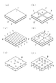
まず、実施例▲5▼〜▲7▼は、断熱部材6の表面部に強固部1を設けるが、柔軟部2を内部のみならず表面部にも強固部1を分割するように設けて、表面部のたわみ性を大きくし、もって前記縮応力により強固部1に亀裂が生じるのを防ぐようにした態様である。
図2(b)に示す実施例▲5▼は、タイルと目地の関係のように、表面部の強固部1の間に柔軟部2を設けた態様である。
図2(c)に示す実施例▲6▼は、表面部において強固部1と柔軟部2とを縞模様のように交互に配した態様である。
図2(d)に示す実施例▲7▼は、表面部の強固部1の中に複数の柔軟部2を島状に設けた態様である。
【0031】
次に、実施例▲8▼及び▲9▼は、容器5の壁に接する断熱部材6の表面部及び表面部より内側の内部に強固部1を複数の島状に分散させて設け、断熱部材6の残部を柔軟部2とした態様である。
図2(e)に示す実施例▲8▼は、強固部1を断熱部材6の面方向及び厚さ方向にランダムな位置に島状に分散させて設けた態様である。
図2(f)に示す実施例▲9▼は、断熱部材6の両面間に延びる柱状の強固部1を分散させた態様である。
【0032】
第二実施形態の断熱部材6も、圧力0.10MPaで圧縮率10%以下を保つことができ、第一実施形態と同様の作用効果を発揮する外、前記の通り、第一実施形態の場合よりも表面に亀裂が生じにくい。
【0033】
なお、本発明は前記実施形態の構成に限定されず、例えば以下のように、発明の趣旨から逸脱しない範囲で適宜変更して具体化することもできる。
(1)真空断熱材の容器が袋状になっていて、封止する部分が、断熱部材に対して1辺だけであること。
(2)無機バインダの付着の態様が、1種類の態様の面方向への繰り返しではなく、複数の態様の組み合わせ、例えば図2(b)と(f)を組み合わせた態様であること。
【0034】
【発明の効果】
以上詳述したように、本発明に係る真空断熱材及びその製造方法によれば、高温使用に適し、十分な耐圧性を有しながら、より軽量で表面の粉っぽさを低減し、繊維の持つ柔軟性を維持しており、断熱性能を長期間維持でき、さらに、比較的容易に製造できるという優れた効果を奏する。
【図面の簡単な説明】
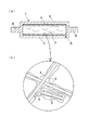
【図1】本発明の実施形態を示し、(a)は真空断熱材の断面図、(b)はその断熱部材の強固部の拡大模式図である。
【図2】(a)は第一実施形態における断熱部材の斜視図、(b)〜(f)は第二実施形態における断熱部材の斜視図である。
【符号の説明】
1 強固部
2 柔軟部
3 セラミック繊維
4 無機バインダ
5 容器
6 断熱部材
7 真空断熱材[0001]
TECHNICAL FIELD OF THE INVENTION
The present invention relates to a vacuum heat insulating material and a method for manufacturing the same.
[0002]
[Prior art]
Conventionally, as vacuum heat insulating material, needling mats, felts, blankets, etc. made of inorganic fibers are housed in heat insulating containers or bags, then vacuumed and closely adhered, or the whole of inorganic fibers is firmly molded with inorganic binder Then, it is known that it is housed in an insulated container or a bag, and then brought into close contact with a vacuum.
[0003]
[Problems to be solved by the invention]
In the case of a vacuum insulating material in which a needling mat, felt, blanket, etc. made of inorganic fibers are housed in an insulated container or bag and evacuated, the insulated container or bag may be deformed due to uneven density of the mat or felt or compression deformation of the fiber mat. It has the problem of waving or denting. Further, when stored in aluminum foil, when used at high temperatures, there is a problem that heat insulation is impaired by radiation from the aluminum itself.
[0004]
In addition, in the case of a vacuum heat insulating material in which an inorganic fiber formed entirely of an inorganic binder is firmly molded in a heat insulating container or bag and evacuated, there is little dent when evacuated, but the whole is solidified with an inorganic binder. Therefore, it does not have elasticity like unglazed porcelain, cracks occur during evacuation, and the heat insulation performance is reduced. This can be imagined as a structure such as a refractory where brittle fracture easily occurs. In this case, a large amount of inorganic binder is required, and it is difficult to deaerate bubbles inside the molding at the time of evacuation. When used as a vacuum heat insulating material for a long time, the gas generated from the bubbles causes vacuum deterioration. The service life of the insulation performance is shortened. Further, when the container is insulated or evacuated as a heat insulating member and evacuated, if the compression ratio exceeds 10%, there is a problem that the insulated container or sack is remarkably dented by the vacuum force. In this case, in order to reduce the compressibility under a pressure of 0.1 MPa (1.02 kg / cm 2 ) to 10% or less, the bulk density needs to be increased, and the thermal conductivity and vacuum degassing properties are reduced. There are points.
[0005]
Furthermore, when an organic binder is used, the pressure resistance and elasticity are superior to those when an inorganic binder is used.However, when the temperature becomes high after vacuum packaging, there is a danger that the organic binder is vaporized, the degree of vacuum is reduced, and the heat insulating performance is deteriorated. There is a problem that it cannot be used at high temperatures.
[0006]
The present invention solves the above-mentioned problems, is suitable for high-temperature use, has sufficient pressure resistance, is lighter, reduces the powderiness of the surface, maintains the flexibility of fibers, and has thermal insulation performance. It is an object of the present invention to provide a vacuum heat insulating material that can be maintained for a long time and that can be manufactured relatively easily.
[0007]
[Means for Solving the Problems]
In order to achieve the above object, the present invention employs the following means (1) and (2).
(1) vacuum insulation material of the present invention, in the vacuum heat insulating material formed by sealing the container or bag while evacuating to fill the heat insulating member made of fiber within the container or the bag, the walls or bag of the container Provide a strong part which is made by binding the intersection of fibers mainly by inorganic binder to a part of the heat insulating member so as to be able to support and suppress the depression or deformation due to the pressure difference between inside and outside during evacuation from inside, In order to prevent the heat insulating member from being cracked by the compressive stress from the container wall or the bag at the time of evacuation, the remaining portion of the heat insulating member is a flexible portion having no or relatively little binding. Depending on the type of the “heat insulating member made of fiber” used as the base material, there is a material that already contains an inorganic binder as a whole. The remaining portion may be used as it is to form a flexible portion.
[0008]
(2) the manufacturing method of the vacuum heat insulating material of the present invention is the manufacturing method of the vacuum heat insulating material formed by sealing the container or bag while evacuating to fill the heat insulating member in the container or the bag, container or before filling the heat insulating member in the bag, mainly water-soluble part of the insulating member so that the walls or bag of the container to recessed or deformed pressure difference between the inside and outside at the time of evacuation can be suppressed supported from the inside A heat insulating member is provided so as to prevent the heat insulating member from breaking due to compressive stress from the wall or bag of the container at the time of vacuum evacuation, by providing an inorganic binder to adhere and dry the fiber, thereby binding the intersections of the fibers to provide a strong portion. Is characterized in that the remaining portion is a flexible portion having no or relatively little binding.
[0009]
In the above means (1) and (2), the "container" covers the entire surface of the heat insulating member when it is in a vacuum state, can maintain the vacuum state for a long time, and does not hinder the performance as the heat insulating member. What is necessary is just a thing, and it is not limited to a specific structure, shape, dimension, etc. The material of the container is not particularly limited, and examples thereof include ordinary stainless steel (including copper-plated products), heat-resistant steel, and oxygen-free copper that generates a small amount of gas.
[0010]
The “fiber” is not particularly limited, but is preferably composed mainly of inorganic fibers. Examples of the inorganic fibers include glass fibers, ceramic fibers such as alumina and silica, slag wool fibers, and rock wool fibers. Also, a small amount of heat-resistant metal fiber (fiber such as stainless steel, chromium-nickel alloy, high nickel alloy, high cobalt alloy, etc.) can be mixed. In this case, the heat insulation performance is slightly reduced, but the heat resistance is high. Become. Although the fiber diameter of the fiber is not particularly limited, it is preferably 1 to 30 μm, and depending on the degree of vacuum, the thinner the fiber, the lower the thermal conductivity and the better the heat insulation performance.
[0011]
The term “mainly inorganic binder” means not only a case where only an inorganic binder is used, but also a case where an inorganic binder is used as a main material and an organic binder is added.
[0012]
The “inorganic binder” is not particularly limited as long as it functions as a binder between fibers, and examples thereof include silica sol, alumina sol, titania sol, zirconia sol, water glass, active silica, clay mineral, aluminum biphosphate, and cement. . These inorganic binders may be used as a mixture. Further, although not particularly limited, active silica and aluminum biphosphate have an action of strengthening the bonding force of silica sol and the like, and it is also preferable to use them in a mixed manner. Further, it is preferable to add a ceramic powder.
When ceramic powder is added, powder having low solid thermal conductivity, titania, silicon nitride, and the like are preferable. By adding the ceramic powder, the air gap is reduced and the gas heat conduction is almost eliminated, so that the vacuum insulation performance is improved. However, the number of heat transfer points of the object increases, and the solid heat conduction through which heat is transmitted in the powder increases, so that the vacuum insulation performance deteriorates. Therefore, it is important to adjust the amount of addition that can minimize the contradictory heat conduction under the temperature condition and the vacuum condition used as the vacuum heat insulating material.
[0013]
The "organic binder" is not particularly limited, and examples thereof include starch-based, silicon-based, and rubber-based.
[0014]
“Cracking” means that a crack propagates in the thickness direction of the heat insulating member, and does not include a case where a crack does not propagate in the thickness direction even if a crack is generated on the surface of the heat insulating member.
[0015]
“No binding or relatively little binding” means that binding by the inorganic binder is smaller than that of the strong part. For example, depending on the type of the “insulating member made of fibers” used as the base material, there is a type that already contains an inorganic binder as a whole, but a part of the inorganic binder is additionally added mainly to the inorganic binder. The strong portion may be used, and the remaining portion may be used as it is (with no additional inorganic binder attached) as the flexible portion.
[0016]
Further, the heat insulating member before the adhesion of the inorganic binder is not particularly limited, but preferably has a flexibility with a compression ratio of 10% or more under a pressure of 0.1 MPa (1.02 kg / cm 2 ), and after the adhesion. The heat insulating member is not particularly limited, but preferably has a bulk density of 100 to 400 kg / m 3 and a compressibility of 10% or less under a pressure of 0.1 MPa. Further, the thickness of the heat insulating member is not particularly limited, but is preferably 30 to 100 mm. In addition, although not particularly limited, when it adheres to the surface of the heat insulating member, the thickness of the inorganic binder in the strong part is preferably 10 mm or less, and the thickness of the flexible part to which the remaining inorganic binder is not adhered is preferably 20 mm or more.
[0017]
The following modes can be exemplified as combinations of the respective portions in "a part of the heat insulating member ... a strong portion" and "a remaining portion of the heat insulating member ... a flexible portion".
(a) A rigid portion is provided on substantially the entire surface of the heat insulating member in contact with the wall or bag of the container, and the inside of the heat insulating member inside the surface is a flexible portion.
(b) A flexible portion is provided on a part of the surface of the heat insulating member so as to divide the strong portion, thereby preventing a crack from being generated in the strong portion due to compressive stress.
(c) Strong portions are dispersed in a plurality of islands in the surface portion of the heat insulating member in contact with the wall or bag of the container and inside the surface portion, and the remaining portion of the heat insulating member is a flexible portion.
[0018]
As in the above means (1) and (2), a strong portion is formed by binding the intersections of the fibers mainly with an inorganic binder, and the propagation of compressive stress from the inner wall of the container or the bag due to evacuation is diffused. By relaxing, the molded shape is maintained, and even if a crack occurs in the strong part, the crack can be prevented from growing in the flexible part, and the heat insulating member can maintain high toughness.
[0019]
When the inorganic binder is attached, an organic binder may be added and the viscosity may be increased as described above in order to adjust the amount of the inorganic binder attached as necessary. Organic components in the organic binder are vaporized and removed by a heat treatment in a subsequent step. The adhesion method is not particularly limited, and examples thereof include a small amount immersion and impregnation method utilizing the capillary action of the fiber molded body, a brush application, a spray or a sponge roller application method, and the like.
[0020]
The mechanism of the compressive stress from the container inner wall or bag shows a uniform stress distribution according to the principle of Pascal if the inside is a material such as water, but it does not hold in the case of a fiber molded body, and it comes into contact with the inner wall It is transmitted by a fiber and a fiber deformed from each intersection, or a fiber that breaks at an intersection, a fiber that is crushed, or the like. Therefore, by increasing the strength of the fiber or each fiber intersection, the resistance to compression is increased, and the compression ratio can be reduced by spreading the stress with the increase in the number of fiber intersections subjected to internal pressure.
[0021]
BEST MODE FOR CARRYING OUT THE INVENTION
An embodiment of a vacuum heat insulating material embodying the present invention and a method of manufacturing the same will be described. Note that the materials, configurations, numerical values, and the like described in the embodiments are merely examples, and can be changed as appropriate.
[0022]
[First embodiment]
FIG. 1 shows a vacuum
[0023]
In order to prevent the wall of the
[0024]
This vacuum
(1) Adhesion Step A commercially available water-soluble inorganic binder 4 (NK Bond TA-10 manufactured by New Life Research Institute) is diluted three times with water to substantially the entire surfaces of both surfaces of the molded flat plate of the
(2) Drying Step The
(3) Vacuum Evacuation Step The
[0025]
Examples (1) to (4), which are
[0026]
[Table 1]
As shown in Table 1, in the case of the untreated comparative example (1), since the compression ratio becomes 15.8% at a pressure of 0.10 MPa, there is a problem that when the container is put into the
On the other hand, in Examples ( 1 ) to (4), when the inorganic binder 4 (100 to 800 g / m 2 ) is adhered to the molded flat plate of the
[0028]
The operation and effect of the vacuum
(1) Due to the presence of the
(2) Even if a crack is generated on the surface (strong part 1) of the
(3) Since the amount of the
(4) Since only a part of the
(5) Since the
[0029]
[Second embodiment]
FIGS. 2B to 2F show the
[0030]
First, in the embodiments (5) to (7), the
Embodiment (5) shown in FIG. 2 (b) is a mode in which a
Embodiment (6) shown in FIG. 2 (c) is a mode in which the
Embodiment (7) shown in FIG. 2 (d) is a mode in which a plurality of
[0031]
Next, in Embodiments (8) and (9), the
Embodiment (8) shown in FIG. 2E is a mode in which the
Embodiment (9) shown in FIG. 2 (f) is a mode in which the columnar
[0032]
The
[0033]
Note that the present invention is not limited to the configuration of the above-described embodiment, and may be embodied with appropriate modifications without departing from the spirit of the invention, for example, as described below.
(1) The vacuum heat insulating material container has a bag shape, and the portion to be sealed is only one side of the heat insulating member.
(2) The mode of adhesion of the inorganic binder is not a repetition of one type in the plane direction but a combination of a plurality of modes, for example, a mode in which FIGS. 2B and 2F are combined.
[0034]
【The invention's effect】
As described in detail above, according to the vacuum heat insulating material and the method for producing the same according to the present invention, it is suitable for use at high temperatures and has sufficient pressure resistance, while reducing the powderiness of the surface with lighter weight, The excellent effect that the heat insulation performance can be maintained for a long period of time and can be manufactured relatively easily.
[Brief description of the drawings]
FIG. 1 shows an embodiment of the present invention, in which (a) is a cross-sectional view of a vacuum heat insulating material, and (b) is an enlarged schematic view of a rigid portion of the heat insulating member.
FIG. 2A is a perspective view of a heat insulating member according to the first embodiment, and FIGS. 2B to 2F are perspective views of the heat insulating member according to the second embodiment.
[Explanation of symbols]
DESCRIPTION OF
Claims (7)
Priority Applications (1)
| Application Number | Priority Date | Filing Date | Title |
|---|---|---|---|
| JP2001349503A JP3548151B2 (en) | 2001-11-14 | 2001-11-14 | Vacuum insulation material and method of manufacturing the same |
Applications Claiming Priority (1)
| Application Number | Priority Date | Filing Date | Title |
|---|---|---|---|
| JP2001349503A JP3548151B2 (en) | 2001-11-14 | 2001-11-14 | Vacuum insulation material and method of manufacturing the same |
Related Child Applications (1)
| Application Number | Title | Priority Date | Filing Date |
|---|---|---|---|
| JP2004066684A Division JP4220921B2 (en) | 2004-03-10 | 2004-03-10 | Heat insulation material for vacuum insulation |
Publications (3)
| Publication Number | Publication Date |
|---|---|
| JP2003148687A JP2003148687A (en) | 2003-05-21 |
| JP3548151B2 true JP3548151B2 (en) | 2004-07-28 |
| JP2003148687A5 JP2003148687A5 (en) | 2005-02-17 |
Family
ID=19162161
Family Applications (1)
| Application Number | Title | Priority Date | Filing Date |
|---|---|---|---|
| JP2001349503A Expired - Lifetime JP3548151B2 (en) | 2001-11-14 | 2001-11-14 | Vacuum insulation material and method of manufacturing the same |
Country Status (1)
| Country | Link |
|---|---|
| JP (1) | JP3548151B2 (en) |
Families Citing this family (5)
| Publication number | Priority date | Publication date | Assignee | Title |
|---|---|---|---|---|
| TW593919B (en) * | 2002-05-31 | 2004-06-21 | Matsushita Refrigeration | Vacuum heat insulating material and method for producing the same, and refrigerator using the vacuum heat insulating material |
| JP2005127409A (en) * | 2003-10-23 | 2005-05-19 | Matsushita Electric Ind Co Ltd | Vacuum heat insulation material, freezing device and cooling-warming device using vacuum heat insulation material |
| JP5049468B2 (en) * | 2005-03-29 | 2012-10-17 | 国立大学法人東北大学 | Insulated container and manufacturing method thereof |
| JP2016211605A (en) * | 2015-04-30 | 2016-12-15 | イビデン株式会社 | Capping material for liquefied gas tank heat insulation material |
| JP7407588B2 (en) * | 2019-12-20 | 2024-01-04 | 東芝ライフスタイル株式会社 | Method of manufacturing insulation material and method of manufacturing refrigerator |
-
2001
- 2001-11-14 JP JP2001349503A patent/JP3548151B2/en not_active Expired - Lifetime
Also Published As
| Publication number | Publication date |
|---|---|
| JP2003148687A (en) | 2003-05-21 |
Similar Documents
| Publication | Publication Date | Title |
|---|---|---|
| JP2020170707A (en) | Microporous insulator | |
| US7497918B2 (en) | Method of siliciding thermostructural composite materials, and parts obtained by the method | |
| KR100634935B1 (en) | Composite Carbonaceous Heat Insulator | |
| CN207395480U (en) | A kind of insulation construction | |
| JP3548151B2 (en) | Vacuum insulation material and method of manufacturing the same | |
| JP4753568B2 (en) | SiC fiber reinforced ceramic composite environment resistant coating and method for producing the same | |
| US20220018485A1 (en) | Composite type heat insulator and method for producing the same | |
| CN107986807A (en) | Anti-oxidant C for a long timefThe preparation method of/C-SiBCN composite materials | |
| JPH07139691A (en) | Vacuum heat insulation material and manufacture thereof | |
| JP5415574B2 (en) | Method for producing heat insulating material for reformer | |
| JP3790694B2 (en) | Glass fiber molded article and molding method thereof | |
| JP4220921B2 (en) | Heat insulation material for vacuum insulation | |
| EP1770324B1 (en) | Heat insulating material | |
| JP4220956B2 (en) | Heat insulation material for vacuum insulation | |
| JP6716296B2 (en) | Porous composite material | |
| JP2003148687A5 (en) | ||
| CN110805788B (en) | Gradient structure heat-insulating material for heat preservation of plane equipment in high-temperature environment | |
| JP2000246821A (en) | Heat resistant material and its manufacture | |
| WO2006114897A1 (en) | Coating agent for thermally insulating material and laminate for thermally insulating material using the same | |
| KR102138324B1 (en) | Thermal insulation structure for engine piston | |
| JP2001173784A (en) | Heat resistant sealant | |
| JPH0157665B2 (en) | ||
| RU2734218C1 (en) | Multilayer carbon material | |
| JPS6148205B2 (en) | ||
| JP3663024B2 (en) | Inorganic fiber molded products |
Legal Events
| Date | Code | Title | Description |
|---|---|---|---|
| A521 | Written amendment |
Free format text: JAPANESE INTERMEDIATE CODE: A523 Effective date: 20040310 |
|
| A621 | Written request for application examination |
Free format text: JAPANESE INTERMEDIATE CODE: A621 Effective date: 20040310 |
|
| A871 | Explanation of circumstances concerning accelerated examination |
Free format text: JAPANESE INTERMEDIATE CODE: A871 Effective date: 20040310 |
|
| A975 | Report on accelerated examination |
Free format text: JAPANESE INTERMEDIATE CODE: A971005 Effective date: 20040322 |
|
| TRDD | Decision of grant or rejection written | ||
| A01 | Written decision to grant a patent or to grant a registration (utility model) |
Free format text: JAPANESE INTERMEDIATE CODE: A01 Effective date: 20040413 |
|
| A61 | First payment of annual fees (during grant procedure) |
Free format text: JAPANESE INTERMEDIATE CODE: A61 Effective date: 20040415 |
|
| R150 | Certificate of patent or registration of utility model |
Ref document number: 3548151 Country of ref document: JP Free format text: JAPANESE INTERMEDIATE CODE: R150 Free format text: JAPANESE INTERMEDIATE CODE: R150 |
|
| R250 | Receipt of annual fees |
Free format text: JAPANESE INTERMEDIATE CODE: R250 |
|
| FPAY | Renewal fee payment (event date is renewal date of database) |
Free format text: PAYMENT UNTIL: 20100423 Year of fee payment: 6 |
|
| FPAY | Renewal fee payment (event date is renewal date of database) |
Free format text: PAYMENT UNTIL: 20100423 Year of fee payment: 6 |
|
| FPAY | Renewal fee payment (event date is renewal date of database) |
Free format text: PAYMENT UNTIL: 20110423 Year of fee payment: 7 |
|
| R250 | Receipt of annual fees |
Free format text: JAPANESE INTERMEDIATE CODE: R250 |
|
| FPAY | Renewal fee payment (event date is renewal date of database) |
Free format text: PAYMENT UNTIL: 20110423 Year of fee payment: 7 |
|
| R250 | Receipt of annual fees |
Free format text: JAPANESE INTERMEDIATE CODE: R250 |
|
| FPAY | Renewal fee payment (event date is renewal date of database) |
Free format text: PAYMENT UNTIL: 20120423 Year of fee payment: 8 |
|
| FPAY | Renewal fee payment (event date is renewal date of database) |
Free format text: PAYMENT UNTIL: 20120423 Year of fee payment: 8 |
|
| FPAY | Renewal fee payment (event date is renewal date of database) |
Free format text: PAYMENT UNTIL: 20130423 Year of fee payment: 9 |
|
| R250 | Receipt of annual fees |
Free format text: JAPANESE INTERMEDIATE CODE: R250 |
|
| FPAY | Renewal fee payment (event date is renewal date of database) |
Free format text: PAYMENT UNTIL: 20130423 Year of fee payment: 9 |
|
| FPAY | Renewal fee payment (event date is renewal date of database) |
Free format text: PAYMENT UNTIL: 20140423 Year of fee payment: 10 |
|
| R250 | Receipt of annual fees |
Free format text: JAPANESE INTERMEDIATE CODE: R250 |
|
| R250 | Receipt of annual fees |
Free format text: JAPANESE INTERMEDIATE CODE: R250 |
|
| R250 | Receipt of annual fees |
Free format text: JAPANESE INTERMEDIATE CODE: R250 |
|
| R250 | Receipt of annual fees |
Free format text: JAPANESE INTERMEDIATE CODE: R250 |
|
| R250 | Receipt of annual fees |
Free format text: JAPANESE INTERMEDIATE CODE: R250 |
|
| R250 | Receipt of annual fees |
Free format text: JAPANESE INTERMEDIATE CODE: R250 |
|
| R250 | Receipt of annual fees |
Free format text: JAPANESE INTERMEDIATE CODE: R250 |
|
| R250 | Receipt of annual fees |
Free format text: JAPANESE INTERMEDIATE CODE: R250 |
|
| R250 | Receipt of annual fees |
Free format text: JAPANESE INTERMEDIATE CODE: R250 |
|
| EXPY | Cancellation because of completion of term |