US10661498B2 - Method for applying a film onto a body - Google Patents
Method for applying a film onto a body Download PDFInfo
- Publication number
- US10661498B2 US10661498B2 US15/545,329 US201515545329A US10661498B2 US 10661498 B2 US10661498 B2 US 10661498B2 US 201515545329 A US201515545329 A US 201515545329A US 10661498 B2 US10661498 B2 US 10661498B2
- Authority
- US
- United States
- Prior art keywords
- film
- gas
- transfer mold
- barrier film
- inner container
- Prior art date
- Legal status (The legal status is an assumption and is not a legal conclusion. Google has not performed a legal analysis and makes no representation as to the accuracy of the status listed.)
- Active, expires
Links
- 238000000034 method Methods 0.000 title claims abstract description 31
- 238000012546 transfer Methods 0.000 claims abstract description 77
- 238000009413 insulation Methods 0.000 claims description 33
- 230000004888 barrier function Effects 0.000 claims description 27
- 239000012790 adhesive layer Substances 0.000 claims description 13
- 239000011162 core material Substances 0.000 claims description 10
- 238000005057 refrigeration Methods 0.000 claims description 6
- 238000004519 manufacturing process Methods 0.000 claims description 3
- 230000002040 relaxant effect Effects 0.000 claims 2
- 230000001070 adhesive effect Effects 0.000 description 10
- 239000000853 adhesive Substances 0.000 description 9
- 239000007789 gas Substances 0.000 description 8
- 210000000038 chest Anatomy 0.000 description 5
- 238000012545 processing Methods 0.000 description 5
- 230000007613 environmental effect Effects 0.000 description 3
- 238000007373 indentation Methods 0.000 description 3
- IJGRMHOSHXDMSA-UHFFFAOYSA-N Atomic nitrogen Chemical compound N#N IJGRMHOSHXDMSA-UHFFFAOYSA-N 0.000 description 2
- 238000005187 foaming Methods 0.000 description 2
- 229910052751 metal Inorganic materials 0.000 description 2
- 239000002184 metal Substances 0.000 description 2
- 239000000843 powder Substances 0.000 description 2
- 229910052782 aluminium Inorganic materials 0.000 description 1
- XAGFODPZIPBFFR-UHFFFAOYSA-N aluminium Chemical compound [Al] XAGFODPZIPBFFR-UHFFFAOYSA-N 0.000 description 1
- QVGXLLKOCUKJST-UHFFFAOYSA-N atomic oxygen Chemical compound [O] QVGXLLKOCUKJST-UHFFFAOYSA-N 0.000 description 1
- 230000015572 biosynthetic process Effects 0.000 description 1
- 230000037237 body shape Effects 0.000 description 1
- 238000007796 conventional method Methods 0.000 description 1
- 238000013461 design Methods 0.000 description 1
- 238000010438 heat treatment Methods 0.000 description 1
- 238000009434 installation Methods 0.000 description 1
- 239000010410 layer Substances 0.000 description 1
- 230000007774 longterm Effects 0.000 description 1
- 239000000463 material Substances 0.000 description 1
- 229910052757 nitrogen Inorganic materials 0.000 description 1
- TWNQGVIAIRXVLR-UHFFFAOYSA-N oxo(oxoalumanyloxy)alumane Chemical compound O=[Al]O[Al]=O TWNQGVIAIRXVLR-UHFFFAOYSA-N 0.000 description 1
- 239000001301 oxygen Substances 0.000 description 1
- 229910052760 oxygen Inorganic materials 0.000 description 1
- 230000002093 peripheral effect Effects 0.000 description 1
- 238000007789 sealing Methods 0.000 description 1
- 239000002356 single layer Substances 0.000 description 1
- 230000007704 transition Effects 0.000 description 1
Images


Classifications
-
- B—PERFORMING OPERATIONS; TRANSPORTING
- B29—WORKING OF PLASTICS; WORKING OF SUBSTANCES IN A PLASTIC STATE IN GENERAL
- B29C—SHAPING OR JOINING OF PLASTICS; SHAPING OF MATERIAL IN A PLASTIC STATE, NOT OTHERWISE PROVIDED FOR; AFTER-TREATMENT OF THE SHAPED PRODUCTS, e.g. REPAIRING
- B29C63/00—Lining or sheathing, i.e. applying preformed layers or sheathings of plastics; Apparatus therefor
- B29C63/0073—Lining or sheathing, i.e. applying preformed layers or sheathings of plastics; Apparatus therefor of non-flat surfaces, e.g. curved, profiled
-
- B—PERFORMING OPERATIONS; TRANSPORTING
- B29—WORKING OF PLASTICS; WORKING OF SUBSTANCES IN A PLASTIC STATE IN GENERAL
- B29C—SHAPING OR JOINING OF PLASTICS; SHAPING OF MATERIAL IN A PLASTIC STATE, NOT OTHERWISE PROVIDED FOR; AFTER-TREATMENT OF THE SHAPED PRODUCTS, e.g. REPAIRING
- B29C63/00—Lining or sheathing, i.e. applying preformed layers or sheathings of plastics; Apparatus therefor
- B29C63/02—Lining or sheathing, i.e. applying preformed layers or sheathings of plastics; Apparatus therefor using sheet or web-like material
- B29C63/04—Lining or sheathing, i.e. applying preformed layers or sheathings of plastics; Apparatus therefor using sheet or web-like material by folding, winding, bending or the like
-
- B—PERFORMING OPERATIONS; TRANSPORTING
- B29—WORKING OF PLASTICS; WORKING OF SUBSTANCES IN A PLASTIC STATE IN GENERAL
- B29C—SHAPING OR JOINING OF PLASTICS; SHAPING OF MATERIAL IN A PLASTIC STATE, NOT OTHERWISE PROVIDED FOR; AFTER-TREATMENT OF THE SHAPED PRODUCTS, e.g. REPAIRING
- B29C65/00—Joining or sealing of preformed parts, e.g. welding of plastics materials; Apparatus therefor
- B29C65/48—Joining or sealing of preformed parts, e.g. welding of plastics materials; Apparatus therefor using adhesives, i.e. using supplementary joining material; solvent bonding
-
- F—MECHANICAL ENGINEERING; LIGHTING; HEATING; WEAPONS; BLASTING
- F25—REFRIGERATION OR COOLING; COMBINED HEATING AND REFRIGERATION SYSTEMS; HEAT PUMP SYSTEMS; MANUFACTURE OR STORAGE OF ICE; LIQUEFACTION SOLIDIFICATION OF GASES
- F25D—REFRIGERATORS; COLD ROOMS; ICE-BOXES; COOLING OR FREEZING APPARATUS NOT OTHERWISE PROVIDED FOR
- F25D23/00—General constructional features
- F25D23/06—Walls
-
- B—PERFORMING OPERATIONS; TRANSPORTING
- B29—WORKING OF PLASTICS; WORKING OF SUBSTANCES IN A PLASTIC STATE IN GENERAL
- B29C—SHAPING OR JOINING OF PLASTICS; SHAPING OF MATERIAL IN A PLASTIC STATE, NOT OTHERWISE PROVIDED FOR; AFTER-TREATMENT OF THE SHAPED PRODUCTS, e.g. REPAIRING
- B29C63/00—Lining or sheathing, i.e. applying preformed layers or sheathings of plastics; Apparatus therefor
- B29C2063/006—Lining or sheathing, i.e. applying preformed layers or sheathings of plastics; Apparatus therefor of surfaces having irregularities or roughness
-
- B—PERFORMING OPERATIONS; TRANSPORTING
- B29—WORKING OF PLASTICS; WORKING OF SUBSTANCES IN A PLASTIC STATE IN GENERAL
- B29C—SHAPING OR JOINING OF PLASTICS; SHAPING OF MATERIAL IN A PLASTIC STATE, NOT OTHERWISE PROVIDED FOR; AFTER-TREATMENT OF THE SHAPED PRODUCTS, e.g. REPAIRING
- B29C2791/00—Shaping characteristics in general
- B29C2791/004—Shaping under special conditions
- B29C2791/006—Using vacuum
-
- B—PERFORMING OPERATIONS; TRANSPORTING
- B29—WORKING OF PLASTICS; WORKING OF SUBSTANCES IN A PLASTIC STATE IN GENERAL
- B29C—SHAPING OR JOINING OF PLASTICS; SHAPING OF MATERIAL IN A PLASTIC STATE, NOT OTHERWISE PROVIDED FOR; AFTER-TREATMENT OF THE SHAPED PRODUCTS, e.g. REPAIRING
- B29C51/00—Shaping by thermoforming, i.e. shaping sheets or sheet like preforms after heating, e.g. shaping sheets in matched moulds or by deep-drawing; Apparatus therefor
- B29C51/10—Forming by pressure difference, e.g. vacuum
-
- B—PERFORMING OPERATIONS; TRANSPORTING
- B29—WORKING OF PLASTICS; WORKING OF SUBSTANCES IN A PLASTIC STATE IN GENERAL
- B29C—SHAPING OR JOINING OF PLASTICS; SHAPING OF MATERIAL IN A PLASTIC STATE, NOT OTHERWISE PROVIDED FOR; AFTER-TREATMENT OF THE SHAPED PRODUCTS, e.g. REPAIRING
- B29C63/00—Lining or sheathing, i.e. applying preformed layers or sheathings of plastics; Apparatus therefor
- B29C63/02—Lining or sheathing, i.e. applying preformed layers or sheathings of plastics; Apparatus therefor using sheet or web-like material
- B29C63/025—Lining or sheathing, i.e. applying preformed layers or sheathings of plastics; Apparatus therefor using sheet or web-like material applied by a die matching with the profile of the surface of resilient articles, e.g. cushions, seat pads
-
- B—PERFORMING OPERATIONS; TRANSPORTING
- B29—WORKING OF PLASTICS; WORKING OF SUBSTANCES IN A PLASTIC STATE IN GENERAL
- B29C—SHAPING OR JOINING OF PLASTICS; SHAPING OF MATERIAL IN A PLASTIC STATE, NOT OTHERWISE PROVIDED FOR; AFTER-TREATMENT OF THE SHAPED PRODUCTS, e.g. REPAIRING
- B29C63/00—Lining or sheathing, i.e. applying preformed layers or sheathings of plastics; Apparatus therefor
- B29C63/02—Lining or sheathing, i.e. applying preformed layers or sheathings of plastics; Apparatus therefor using sheet or web-like material
- B29C63/04—Lining or sheathing, i.e. applying preformed layers or sheathings of plastics; Apparatus therefor using sheet or web-like material by folding, winding, bending or the like
- B29C63/048—Lining or sheathing, i.e. applying preformed layers or sheathings of plastics; Apparatus therefor using sheet or web-like material by folding, winding, bending or the like specially adapted for articles having local protrusions, e.g. tubes having a bead weld
-
- B—PERFORMING OPERATIONS; TRANSPORTING
- B29—WORKING OF PLASTICS; WORKING OF SUBSTANCES IN A PLASTIC STATE IN GENERAL
- B29K—INDEXING SCHEME ASSOCIATED WITH SUBCLASSES B29B, B29C OR B29D, RELATING TO MOULDING MATERIALS OR TO MATERIALS FOR MOULDS, REINFORCEMENTS, FILLERS OR PREFORMED PARTS, e.g. INSERTS
- B29K2105/00—Condition, form or state of moulded material or of the material to be shaped
- B29K2105/25—Solid
- B29K2105/253—Preform
- B29K2105/256—Sheets, plates, blanks or films
-
- B—PERFORMING OPERATIONS; TRANSPORTING
- B29—WORKING OF PLASTICS; WORKING OF SUBSTANCES IN A PLASTIC STATE IN GENERAL
- B29L—INDEXING SCHEME ASSOCIATED WITH SUBCLASS B29C, RELATING TO PARTICULAR ARTICLES
- B29L2031/00—Other particular articles
- B29L2031/712—Containers; Packaging elements or accessories, Packages
-
- B—PERFORMING OPERATIONS; TRANSPORTING
- B32—LAYERED PRODUCTS
- B32B—LAYERED PRODUCTS, i.e. PRODUCTS BUILT-UP OF STRATA OF FLAT OR NON-FLAT, e.g. CELLULAR OR HONEYCOMB, FORM
- B32B2307/00—Properties of the layers or laminate
- B32B2307/30—Properties of the layers or laminate having particular thermal properties
- B32B2307/304—Insulating
-
- B—PERFORMING OPERATIONS; TRANSPORTING
- B32—LAYERED PRODUCTS
- B32B—LAYERED PRODUCTS, i.e. PRODUCTS BUILT-UP OF STRATA OF FLAT OR NON-FLAT, e.g. CELLULAR OR HONEYCOMB, FORM
- B32B37/00—Methods or apparatus for laminating, e.g. by curing or by ultrasonic bonding
- B32B37/10—Methods or apparatus for laminating, e.g. by curing or by ultrasonic bonding characterised by the pressing technique, e.g. using action of vacuum or fluid pressure
- B32B37/1018—Methods or apparatus for laminating, e.g. by curing or by ultrasonic bonding characterised by the pressing technique, e.g. using action of vacuum or fluid pressure using only vacuum
-
- B—PERFORMING OPERATIONS; TRANSPORTING
- B32—LAYERED PRODUCTS
- B32B—LAYERED PRODUCTS, i.e. PRODUCTS BUILT-UP OF STRATA OF FLAT OR NON-FLAT, e.g. CELLULAR OR HONEYCOMB, FORM
- B32B38/00—Ancillary operations in connection with laminating processes
- B32B38/18—Handling of layers or the laminate
- B32B38/1858—Handling of layers or the laminate using vacuum
-
- F—MECHANICAL ENGINEERING; LIGHTING; HEATING; WEAPONS; BLASTING
- F25—REFRIGERATION OR COOLING; COMBINED HEATING AND REFRIGERATION SYSTEMS; HEAT PUMP SYSTEMS; MANUFACTURE OR STORAGE OF ICE; LIQUEFACTION SOLIDIFICATION OF GASES
- F25D—REFRIGERATORS; COLD ROOMS; ICE-BOXES; COOLING OR FREEZING APPARATUS NOT OTHERWISE PROVIDED FOR
- F25D2201/00—Insulation
- F25D2201/10—Insulation with respect to heat
- F25D2201/14—Insulation with respect to heat using subatmospheric pressure
-
- F—MECHANICAL ENGINEERING; LIGHTING; HEATING; WEAPONS; BLASTING
- F25—REFRIGERATION OR COOLING; COMBINED HEATING AND REFRIGERATION SYSTEMS; HEAT PUMP SYSTEMS; MANUFACTURE OR STORAGE OF ICE; LIQUEFACTION SOLIDIFICATION OF GASES
- F25D—REFRIGERATORS; COLD ROOMS; ICE-BOXES; COOLING OR FREEZING APPARATUS NOT OTHERWISE PROVIDED FOR
- F25D2500/00—Problems to be solved
- F25D2500/02—Geometry problems
Definitions
- the present invention relates to a method of applying a film to a body as well as to a vacuum insulation body having a film that has been applied in accordance with the method of the invention.
- the present invention furthermore relates to a heat insulated receptacle and preferably to a refrigerator unit and/or a freezer unit that comprises a vacuum insulation body.
- Vacuum insulation bodies are used, for example, in heat insulation in refrigerator units and freezer units.
- a vacuum insulation body is arranged in the region between the outer jacket of the unit and the inner container to be cooled to achieve a sufficiently high thermal insulation between the outside and the inside of the unit to be insulated by means of the principle of vacuum thermal insulation.
- a film like cover for a vacuum insulation body is described in the patent application DE 10 2013 005 585 that is characterized in that the cover prefabricated in bag form is used as a diffusion-tight cover that is preferably larger than the contour to be covered so that projecting or set back contours of a body to be covered can be covered or film-coated with the film-like cover.
- a method can also be seen from this application how the film-like cover can be applied to the body to be covered.
- the film-like cover prefabricated in bag shape is applied to the body to be covered by means of vacuum. Since the body to be covered or the film typically has adhesive surfaces for the covering, the problem occurs in this respect that the film adheres to the body in a non-dislocatable manner on a contact with the body. A readjustment of the film position on the body is thus not possible.
- a fast setting adhesive or a fast setting adhesive surface is nevertheless useful to enable a processing that is as fast as possible.
- FIG. 3 in this respect shows the problems that occur in the prior art.
- the problem On a pulling over of an over-large film sack and a subsequent application of a vacuum between the film and the body to be film coated, the problem in particular arises with concave or convex contours of the body that the film first comes into contact with the projecting contour sections and adheres to them.
- This has the result that a complete contact of the film in a concave part region of the body cannot be achieved despite a still present film surface.
- Tautened film regions 12 thus result in the region of a concave contour 22 of the body.
- a film is applied to and positioned at a transfer mold, the body to be film coated is introduced into the transfer mold to which the film to be attached is applied or the transfer mold to which the film to be attached is applied is introduced into the body to be film coated so that the film is located between the body and the transfer mold.
- a vacuum is furthermore applied in a region between the body and the film and/or an excess pressure is applied in a region between the transfer mold and the film so that the film moves from the transfer mold onto the body.
- the film to be applied to the body is preferably a high barrier film.
- the term high barrier film is preferably to be understood as a cover or as a film by means of which the gas entry into a vacuum insulation body is reduced so much that the increase in the thermal conductivity due to the gas entry over its service life is sufficiently small.
- a time period of 15 years, preferably of 20 years, and particularly preferably of 30 years, is to be considered as the service life, for example.
- the increase in the thermal conductivity of the vacuum insulation body caused by gas entry is preferably less than 100%, and particularly preferably less than 50%, over its service life.
- the surface-specific gas permeation rate of the high barrier film is preferably less than 10 ⁇ 5 mbar*l/s*m 2 and particularly preferably less than 10 ⁇ 6 mbar*l/s*m 2 (measured according to ASTM D-3985). This gas permeation rate applies to nitrogen and to oxygen. There are likewise low gas permeation rates for other types of gas (in particular steam), preferably in the range from less than 10 ⁇ 2 mbar*l/s*m 2 and particularly preferably in the range from less than 10 ⁇ 3 mbar*l/s*m 2 (measured according to ASTM F-1249-90). The aforesaid small increases in the thermal conductivity are preferably achieved by these small gas permeation rates.
- a high barrier film preferably comprises a single-layer film or a multi-layer film (that is preferably sealable) having one or more barrier films (typically metal films or oxide films, with aluminum or an aluminum oxide typically being used as the metal or as the oxide respectively).
- barrier films typically metal films or oxide films, with aluminum or an aluminum oxide typically being used as the metal or as the oxide respectively.
- a pressure difference is formed between the region of the film and the body and the region of the film and the transfer mold.
- the pressure difference is in this respect configured such that the film applied to the transfer mold is removed from it and moved in the direction of the body. A particularly simple application of a film to a body is thereby achieved.
- the transfer mold preferably has a smooth surface so that a film contacting the transfer mold can be simply positioned. A manual repositioning of a film contacting the transfer mold can naturally also be considered in this respect.
- a vacuum is formed between the film and the transfer mold for applying and positioning the film to and at the transfer mold.
- a pressure difference is therefore provided in a space formed by the film and the transfer mold so that the film moves in the direction of the transfer mold.
- An adhesion of the film to the transfer mold is thereby insured in a simple manner.
- a peeling of a film once applied to the transfer mold is also countered by forming a vacuum between the film and the transfer mold so that the body to be film coated can already be brought into a direct vicinity of the transfer mold having the applied film without the film peeling from it in an unwanted manner and coming into contact with the body.
- a transition of the film onto the body to be film coated first takes place by a provision of a pressure difference that causes a movement of the film in the direction of the body.
- the body to be film coated is advantageously partly or completely provided with an adhesive layer at its surfaces to be film coated before a transfer of the film to the body and/or the side of the film contacting the body is partly or completely provided with an adhesive layer at its surfaces contacting the body before a transfer of the film to the body.
- an adhesive layer results in a fast processing and a long-term connection of the film to the body.
- a fast-setting adhesive for the adhesive layer.
- the adhesive layer is located both on the body to be film coated and on the film to be applied to the body. A combination of adhesive layer on the body and of adhesive player on the film is also possible.
- the adhesive layer is, however, preferably applied to the body to be film coated since it, unlike the film, has a rigid base structure on which the application of an adhesive layer can be implemented more easily.
- the transfer mold has at a surface of the body to be film located that has an elevated portion and/or a recess a recess contrary thereto.
- the body is aligned with respect to the transfer mold before a transfer of the film to the body such that respective corresponding pairs of an elevated portion and/or of a recess of the body and of a recess of the transfer mold are aligned with respect to one another.
- the transfer mold has a corresponding recess so that the region formed by the body and the transfer mold widens at this position both due to the body and due to the transfer mold.
- This describes a corresponding pairing of a recess of body and transfer mold and also defines a contrary recess that the transfer mold has with respect to a recess of the surface of the body to be film coated.
- a recess of the transfer mold is therefore provided at a recess of the body to film coated (concave contour). These two contours accordingly project from one another.
- the recess in a surface of the body can be completely covered with film on the transfer procedure of the film from the transfer mold to the body without the parts of the body in the recess not being able to be covered by a film.
- a film is preferably also provided in a recess of the transfer mold that can then be applied in the contour of the body formed contrary thereto.
- the film for application to the body has a bag-shaped base structure and is preferably a high barrier film.
- Both the application of the film to a transfer mold and the transfer to the body to be film coated can be performed particularly simply due to the bag-shaped base structure of the film.
- the film for application to the body is preferably larger than the surfaces of the body to be film coated. It is thereby ensured that a sufficient amount of film is present to cover the total surface of the body to be film coated. No stresses are thus furthermore formed in the film applied to the body, whereby regions of the body that are not covered by film are minimized.
- the transfer mold can completely receive the body to be film coated in an opening or the body to be film coated can completely receive the transfer mold in an opening.
- the body to be film coated is the inner container of a heat-insulated receptacle and preferably the inner container of a refrigerator unit and/or a freezer unit.
- a heat-insulated receptacle and preferably the inner container of a refrigerator unit and/or a freezer unit.
- Different embodiments of such receptacles and units covered by the invention will be described in detail further below.
- the present invention furthermore relates to a vacuum insulation body that has a film, preferably a high barrier film that has been attached to the body to be film coated in accordance with one of the embodiments of the method in accordance with the invention described above.
- a core material of the vacuum insulation body in this respect advantageously comprises a bulk powder that is covered in a diffusion-tight manner by the film.
- the film has folds projecting in the direction of the core material.
- the folds projecting in the direction of the core material result from an application of one of the embodiments of the method for applying a film onto a body.
- the present invention furthermore relates to a heat insulated receptacle, preferably to a refrigerator unit and/or a freezer unit, that contains at least one vacuum insulation body that has been produced with the aid of one of the methods described above.
- the invention furthermore relates to a heat insulated receptacle, preferably to a refrigerator unit and/or a freezer unit, having at least one carcass and having at least one temperature-controlled and preferably cooled inner space that is surrounded by the carcass and having at least one closure element by means of which the temperature-controlled and preferably cooled inner space is closable, wherein at least one intermediate space is located between the temperature-controlled and preferably cooled inner space and the outer wall of the receptacle or of the unit, wherein at least one vacuum insulation body having an evacuated region surrounded by a film and filled with core material is arranged in the intermediate space; and wherein at least one section of the film was applied to the inner container of the receptacle or of the unit within the framework of a method in accordance with the invention.
- a heat insulation is to be understood by this which comprises only or primarily an evacuated region which is filled with a core material. Only such a vacuum insulation body can thus be present between the inner wall and the outer wall of the receptacle or unit which has a region which is surrounded by a vacuum-tight film, in which there is a vacuum and in which a core material is arranged.
- a foaming and/or a vacuum insulation panel is/are preferably not provided as heat insulation or another heat insulation is not provided, except for the full vacuum system between the inner side and the outer side of the receptacle or unit.
- This preferred form of heat insulation in the form of a full vacuum system can extend between the wall bounding the inner space and the outer wall of the carcass and/or between the inner side and the outer side of the closure element such as a door, flap, cover, or the like.
- the full vacuum system can be obtained such that a covering of a gas-tight film is filled with a core material and is subsequently sealed in a vacuum-tight manner.
- both the filling and the vacuum-tight sealing of the covering take place at normal or environmental pressure.
- the evacuation then takes place by the connection to a vacuum pump of a suitable interface worked into the covering, for example an evacuation stub which can have a valve.
- Normal or environmental pressure is preferably present outside the covering during the evacuation. In this embodiment, it is preferably not necessary at any time of the manufacture to introduce the covering into a vacuum chamber.
- a vacuum chamber can be dispensed with in an embodiment to this extent during the manufacture of the vacuum insulation.
- the temperature-controlled inner space is either cooled or heated depending on the type of the unit (refrigerator unit, heating cabinet, etc.)
- Heat insulated receptacles in the sense of the present invention have at least one temperature-controlled inner space, with this being able to be cooled or heated so that a temperature results in the inner space below or above the environmental temperature of e.g. 21° C.
- the invention is therefore not restricted to refrigerator units and/or freezer units, but rather generally applies to units having a temperature-controlled inner space, for example also to heat cabinets or heat chests.
- the receptacle in accordance with the invention is a refrigerator unit and/or a freezer unit, in particular a domestic appliance or a commercial refrigerator.
- Such units are, for example, covered which are designed for a stationary arrangement at a home, in a hotel room, in a commercial kitchen or in a bar. It can, for example, be a wine cooler. Chest refrigerators and/or freezers are furthermore also covered by the invention.
- the units in accordance with the invention can have an interface for connection to a power supply, in particular to a domestic mains supply (e.g. a plug) and/or can have a standing aid or installation aid such as adjustment feet or an interface for fixing within a furniture niche.
- the unit can, for example, be a built-in unit or also a stand-alone unit.
- the receptacle or the unit is preferably configured such that it can be operated at an AC voltage such as a domestic mains voltage of e.g. 120 V and 60 Hz or of 230 V and 50 Hz. It is conceivable in an alternative embodiment that the receptacle or the unit is configured such that it can be operated with DC current of a voltage of, for example, 5 V, 12 V or 24 V. Provision can be made in this embodiment that a plug power supply is provided inside or outside the unit via which the unit is operated. Operation with DC voltage can in particular be used when the receptacle has a thermoelectric heat pump for controlling the temperature of the inner space.
- the refrigerator unit and/or freezer unit has/have a cabinet-type design and has/have a useful space which is accessible to a user at its front side (at the upper side in the case of a chest).
- the useful space can be divided into a plurality of compartments which are all operated at the same temperature or at different temperatures. Alternatively, only one compartment can be provided.
- Storage aids such as trays, drawers or bottle-holders (also dividers in the case of a chest) can also be provided within the useful space or within a compartment to ensure an ideal storage of refrigerated goods or frozen goods and an ideal use of the space.
- the useful space can be closed by at least one door pivotable about a vertical axis.
- a lid pivotable about a horizontal axis or a sliding lid is conceivable as the closing element.
- the door or another closing element can be connected in a substantially airtight manner to the carcass by a peripheral magnetic seal in the closed state.
- the door or another closing element is preferably also heat insulated, with the heat insulation being able to be achieved by a foaming and optionally by vacuum insulation panels or also preferably by a vacuum system and particularly preferably by a full vacuum system.
- Door storage areas can optionally be provided at the inside of the door in order also to be able to store refrigerated goods there.
- the useful space defined by the inner wall of the container has, for example, a volume of less than 0.5 m 3 , less than 0.4 m 3 or less than 0.3 m 3 .
- the outer dimensions of the container or unit are preferably in the range up to 1 m with respect to the height, width and depth.
- a vacuum insulation body can be molded to such an auxiliary mold that is connected to the cover body by a thin adhesive layer on completion of the evacuation procedure. This is, for example, but not exclusively, possible for an areal vacuum contour body, e.g. for use in a refrigeration unit door.
- the cover is in particular used for a vacuum insulation element in which indentations or dimples are present that have a rectangular outline.
- This can e.g. also be a complete receptacle composed of a vacuum insulation body in which in the simplest case of a rectangular receptacle the inner space is understood as an indentation into the covering cuboid.
- a film fold proves to be expedient in which film folds project into the later insulation space in the corner regions.
- This easily understandable kind of film fold at the corner regions can, however, also be seen in general terms as a product feature of a vacuum insulation body manufactured in accordance with the method in accordance with the invention. The feature is in this respect a film fold that projects into the bulk powder of the core material.
- FIG. 1 a sectional view of a transform mold which a film contacts and into which a body to be film coated is introduced;
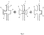
- FIG. 2 the procedure of a film transfer in the region of a recess of the body to be film coated
- FIG. 3 the result of an application of a film to a body in accordance with a conventional method.
- FIG. 3 shows the result of a method of applying a film to a body in accordance with the prior art.
- a film is pulled over a body provided with adhesive and a vacuum is generated between the film and the body for applying the film. Since the adhesive on the body no longer permits a dislocation of the film after a contact with the film, regions form in recesses 22 of the body (concave contours) in which the film is not completely in contact with the body. Tautened regions 12 of the film are rather formed that result in the region of recesses 22 (concave contours) of the body.
- tautened surfaces 12 and the film folds 11 represent an obstacle to the further processing of a body provided with film and are additionally very prone to damage
- tautened surfaces of the film should generally be avoided.
- special attention is placed on the tautened surfaces 12 of the film since they are very specifically prone to damage of the film on a small force application.
- FIG. 1 shows a transfer mold 3 to which a film 1 has been applied.
- a body 2 has furthermore been introduced into the transfer mold 3 so that a film 1 is arranged between the body 2 and the transfer mold 3 .
- a recess (concave contour) of the body 2 and a cutout 4 corresponding thereto in the transfer mold 3 can furthermore be recognized that is oriented opposite the recess 5 of the body 2 . It can also be recognized that the film is also present in a part of this cut-out 4 of the transfer mold 3 .
- the film 1 is typically applied to the transfer mold by applying a vacuum between the region of the film 1 and the transfer mold 3 . It is thus ensured that a body 2 provided with an adhesive, for example, does not come into contact with the film in an unwanted manner. As long as a sufficient distance from the transfer mold 3 is observed.
- FIG. 2 shows a transfer of the film 1 from the transfer mold 3 to the body 2 .
- the film 1 is still applied to the transfer mold 3 in the left of the three illustrations of FIG. 2 .
- the center representation shows a state of the film in which the latter has not yet completely come into contact with all the surfaces of the body 2 .
- a pressure difference between the regions of the film and the transfer mold 3 and the film 1 and the body 2 has already been applied such that the film 1 peels off the transfer mold 3 and moves in the direction of the body 2 .
- An excess film provided in a cut-out 4 of the transfer mold 3 is being applied in the direction of the recess (concave contour) 5 of the body 2 .
Abstract
Description
Claims (7)
Applications Claiming Priority (5)
| Application Number | Priority Date | Filing Date | Title |
|---|---|---|---|
| DE102015000822 | 2015-01-22 | ||
| DE102015000822.6 | 2015-01-22 | ||
| DE102015008161.6 | 2015-06-24 | ||
| DE102015008161.6A DE102015008161A1 (en) | 2015-01-22 | 2015-06-24 | Method for applying a film to a body |
| PCT/EP2015/002166 WO2016116118A1 (en) | 2015-01-22 | 2015-10-29 | Method for applying a film onto a body |
Publications (2)
| Publication Number | Publication Date |
|---|---|
| US20180009156A1 US20180009156A1 (en) | 2018-01-11 |
| US10661498B2 true US10661498B2 (en) | 2020-05-26 |
Family
ID=56364332
Family Applications (1)
| Application Number | Title | Priority Date | Filing Date |
|---|---|---|---|
| US15/545,329 Active 2035-11-30 US10661498B2 (en) | 2015-01-22 | 2015-10-29 | Method for applying a film onto a body |
Country Status (7)
| Country | Link |
|---|---|
| US (1) | US10661498B2 (en) |
| EP (1) | EP3247550B1 (en) |
| CN (1) | CN107530953B (en) |
| DE (1) | DE102015008161A1 (en) |
| ES (1) | ES2865174T3 (en) |
| RU (1) | RU2672750C1 (en) |
| WO (1) | WO2016116118A1 (en) |
Families Citing this family (1)
| Publication number | Priority date | Publication date | Assignee | Title |
|---|---|---|---|---|
| DE102022130725A1 (en) | 2022-10-24 | 2024-04-25 | Liebherr-Hausgeräte Ochsenhausen GmbH | Thermally insulated product |
Citations (18)
| Publication number | Priority date | Publication date | Assignee | Title |
|---|---|---|---|---|
| US2201706A (en) * | 1936-09-21 | 1940-05-21 | Sukohl Heinrich | Method of coating the blades of air propellers |
| US2932142A (en) * | 1955-03-28 | 1960-04-12 | Int Standard Electric Corp | Device for opening letter envelopes, bags, or like articles |
| US3753830A (en) * | 1970-07-13 | 1973-08-21 | United States Steel Corp | Apparatus for laminating a plastic sheet onto a surface of a hollow body |
| JPS58179614A (en) * | 1982-04-14 | 1983-10-20 | Howa Seni Kogyo Kk | Cuticle-adhering method for deep-drawn interior automotive trim |
| EP0442691A1 (en) | 1990-02-16 | 1991-08-21 | Hoover Universal,Inc. | Method of forming a vehicle seat with a removable vacuum seal |
| US5227245A (en) * | 1990-04-04 | 1993-07-13 | The Dow Chemical Company | Barrier films for preventing solvent attack on plastic resins |
| DE29617600U1 (en) | 1996-10-09 | 1997-02-20 | Heidel Gmbh & Co Kg Werkzeug U | Device for the production of laminated moldings |
| US5900299A (en) * | 1996-12-23 | 1999-05-04 | Wynne; Nicholas | Vacuum insulated panel and container and method of production |
| US6128914A (en) * | 1997-04-25 | 2000-10-10 | Sanyo Electric Co., Ltd. | Low temperature storage cabinet |
| US6321513B1 (en) * | 1996-10-17 | 2001-11-27 | Pi-Patente Gesellschaft Mit Beschränkter Haftung (Gmbh) Entwicklung Und Verwertung | Method for packing articles in an elastic packing material and device to carry out said method |
| WO2002026475A2 (en) | 2000-09-28 | 2002-04-04 | Cascade Engineering, Inc. | Process and apparatus for controlling vacuum forming |
| US20030082357A1 (en) * | 2001-09-05 | 2003-05-01 | Cem Gokay | Multi-layer core for vacuum insulation panel and insulated container including vacuum insulation panel |
| EP1510747A1 (en) | 2002-05-31 | 2005-03-02 | Matsushita Refrigeration Company | Vacuum thermal insulating material, process for producing the same and refrigerator including the same |
| US20060243372A1 (en) | 2005-05-02 | 2006-11-02 | Robert Burkle Gmbh | Method for the coating of work pieces |
| EP2314518A1 (en) * | 2009-10-23 | 2011-04-27 | Poli-Box Italiana S.R.L. | Method for providing a container for liquid products and the like, with simplified disposal |
| US20130089696A1 (en) * | 2010-07-02 | 2013-04-11 | Kingspan Holdings (IRL)Limited | Prefabricated composite insulation board |
| DE102013005585A1 (en) | 2013-02-07 | 2014-08-07 | Liebherr-Hausgeräte Lienz Gmbh | Vakuumdämmkörper |
| US20140216100A1 (en) * | 2013-02-06 | 2014-08-07 | Samsung Electronics Co., Ltd. | Vacuum insulation material, insulation case unit, and refrigerator |
Family Cites Families (4)
| Publication number | Priority date | Publication date | Assignee | Title |
|---|---|---|---|---|
| US2781078A (en) * | 1953-09-09 | 1957-02-12 | Nixon Nitration Works | Apparatus for vacuum forming ductile material |
| IT220732Z2 (en) * | 1990-11-28 | 1993-11-08 | Fiat Auto Spa | FRAME FOR HOLDING COVERING PANELS FOR PRINTED ELEMENTS. |
| US6517649B1 (en) * | 2000-09-28 | 2003-02-11 | Cascade Engineering, Inc. | Process for controlling vacuum forming |
| RU2304588C2 (en) * | 2004-11-29 | 2007-08-20 | Федеральное Государственное Унитарное Предприятие "Научно-исследовательский физико-химический институт им. Л.Я. Карпова" (НИФХИ им. Л.Я. Карпова) | Method for applying highly heat-stable thin films made of polytetrafluoroethylene on surface of solid body |
-
2015
- 2015-06-24 DE DE102015008161.6A patent/DE102015008161A1/en not_active Withdrawn
- 2015-10-29 RU RU2017129546A patent/RU2672750C1/en active
- 2015-10-29 EP EP15794822.5A patent/EP3247550B1/en active Active
- 2015-10-29 US US15/545,329 patent/US10661498B2/en active Active
- 2015-10-29 CN CN201580074066.8A patent/CN107530953B/en active Active
- 2015-10-29 ES ES15794822T patent/ES2865174T3/en active Active
- 2015-10-29 WO PCT/EP2015/002166 patent/WO2016116118A1/en active Application Filing
Patent Citations (22)
| Publication number | Priority date | Publication date | Assignee | Title |
|---|---|---|---|---|
| US2201706A (en) * | 1936-09-21 | 1940-05-21 | Sukohl Heinrich | Method of coating the blades of air propellers |
| US2932142A (en) * | 1955-03-28 | 1960-04-12 | Int Standard Electric Corp | Device for opening letter envelopes, bags, or like articles |
| US3753830A (en) * | 1970-07-13 | 1973-08-21 | United States Steel Corp | Apparatus for laminating a plastic sheet onto a surface of a hollow body |
| JPS58179614A (en) * | 1982-04-14 | 1983-10-20 | Howa Seni Kogyo Kk | Cuticle-adhering method for deep-drawn interior automotive trim |
| EP0442691A1 (en) | 1990-02-16 | 1991-08-21 | Hoover Universal,Inc. | Method of forming a vehicle seat with a removable vacuum seal |
| US5227245A (en) * | 1990-04-04 | 1993-07-13 | The Dow Chemical Company | Barrier films for preventing solvent attack on plastic resins |
| DE29617600U1 (en) | 1996-10-09 | 1997-02-20 | Heidel Gmbh & Co Kg Werkzeug U | Device for the production of laminated moldings |
| US6321513B1 (en) * | 1996-10-17 | 2001-11-27 | Pi-Patente Gesellschaft Mit Beschränkter Haftung (Gmbh) Entwicklung Und Verwertung | Method for packing articles in an elastic packing material and device to carry out said method |
| US5900299A (en) * | 1996-12-23 | 1999-05-04 | Wynne; Nicholas | Vacuum insulated panel and container and method of production |
| US6128914A (en) * | 1997-04-25 | 2000-10-10 | Sanyo Electric Co., Ltd. | Low temperature storage cabinet |
| WO2002026475A2 (en) | 2000-09-28 | 2002-04-04 | Cascade Engineering, Inc. | Process and apparatus for controlling vacuum forming |
| US20030082357A1 (en) * | 2001-09-05 | 2003-05-01 | Cem Gokay | Multi-layer core for vacuum insulation panel and insulated container including vacuum insulation panel |
| EP1510747A1 (en) | 2002-05-31 | 2005-03-02 | Matsushita Refrigeration Company | Vacuum thermal insulating material, process for producing the same and refrigerator including the same |
| US20060243372A1 (en) | 2005-05-02 | 2006-11-02 | Robert Burkle Gmbh | Method for the coating of work pieces |
| EP1719604A2 (en) | 2005-05-02 | 2006-11-08 | Robert Bürkle GmbH | Method for lining of objects |
| EP2314518A1 (en) * | 2009-10-23 | 2011-04-27 | Poli-Box Italiana S.R.L. | Method for providing a container for liquid products and the like, with simplified disposal |
| US20130089696A1 (en) * | 2010-07-02 | 2013-04-11 | Kingspan Holdings (IRL)Limited | Prefabricated composite insulation board |
| US20140216100A1 (en) * | 2013-02-06 | 2014-08-07 | Samsung Electronics Co., Ltd. | Vacuum insulation material, insulation case unit, and refrigerator |
| EP2765375A2 (en) | 2013-02-06 | 2014-08-13 | Samsung Electronics Co., Ltd | Vacuum insulation material, insulation case unit, and refrigerator |
| DE102013005585A1 (en) | 2013-02-07 | 2014-08-07 | Liebherr-Hausgeräte Lienz Gmbh | Vakuumdämmkörper |
| US20150377546A1 (en) | 2013-02-07 | 2015-12-31 | Liebherr-Hausgeräte Lienz Gmbh | Vacuum insulation body |
| US10088221B2 (en) * | 2013-02-07 | 2018-10-02 | Liebherr-Hausgeräte Lienz Gmbh | Vacuum insulation body |
Non-Patent Citations (2)
| Title |
|---|
| International Search Report and Written Opinion issued in corresponding International Patent Application No. PCT/EP2015/002166 (with English translation of International Search Report) dated Apr. 20, 2016 (18 pages). |
| Search Report issued in corresponding German Patent Application No. 10 2015 008 161.6 dated Aug. 26, 2015 (10 pages). |
Also Published As
| Publication number | Publication date |
|---|---|
| WO2016116118A1 (en) | 2016-07-28 |
| CN107530953A (en) | 2018-01-02 |
| DE102015008161A1 (en) | 2016-07-28 |
| US20180009156A1 (en) | 2018-01-11 |
| CN107530953B (en) | 2020-08-25 |
| EP3247550B1 (en) | 2021-02-17 |
| ES2865174T3 (en) | 2021-10-15 |
| RU2672750C1 (en) | 2018-11-19 |
| EP3247550A1 (en) | 2017-11-29 |
Similar Documents
| Publication | Publication Date | Title |
|---|---|---|
| RU2674062C1 (en) | Vacuum insulation body | |
| US10697697B2 (en) | Vacuum insulated door structure and method for the creation thereof | |
| US20230324106A1 (en) | Attachment arrangement for vacuum insulated door | |
| EP2690387B1 (en) | Refrigerator vegetable room | |
| US20160258670A1 (en) | Appliance door with vacuum insulated outer door | |
| US10670326B2 (en) | Vacuum-tight through-film bushing | |
| US10640278B2 (en) | Vacuum insulation body | |
| US10690395B2 (en) | Vacuum insulation body | |
| US20170122627A1 (en) | Vacuum Damping Element With A Thermoelectric Element | |
| CN104180578A (en) | Refrigerator | |
| KR20160065679A (en) | Refrigerator | |
| US20190316832A1 (en) | Vacuum Insulation Body | |
| US20200191451A1 (en) | Thermally Insulated Receptacle | |
| US10661498B2 (en) | Method for applying a film onto a body | |
| CN106461309A (en) | Refrigerator | |
| RU2686362C2 (en) | Tempered container | |
| KR20140132522A (en) | Refrigerator | |
| CN206861992U (en) | A kind of new refrigerator drawer turnover panel | |
| WO2022111474A1 (en) | Refrigeration appliance with joint partition plate | |
| US20170131001A1 (en) | Thermoelectrically cooled or heated container | |
| KR20090133013A (en) | Side by side type refrigerator | |
| KR19980027187U (en) | Cold air leak prevention device of refrigerator | |
| KR20140139878A (en) | Vegetables container and refrigerator having the same |
Legal Events
| Date | Code | Title | Description |
|---|---|---|---|
| AS | Assignment |
Owner name: LIEBHERR-HAUSGERATE OCHSENHAUSEN GMBH, GERMANY Free format text: ASSIGNMENT OF ASSIGNORS INTEREST;ASSIGNORS:HIEMEYER, JOCHEN;FREITAG, MICHAEL;KERSTNER, MARTIN;SIGNING DATES FROM 20170824 TO 20170829;REEL/FRAME:043542/0208 Owner name: LIEBHERR-HAUSGERATE LIENZ GMBH, AUSTRIA Free format text: ASSIGNMENT OF ASSIGNORS INTEREST;ASSIGNORS:HIEMEYER, JOCHEN;FREITAG, MICHAEL;KERSTNER, MARTIN;SIGNING DATES FROM 20170824 TO 20170829;REEL/FRAME:043542/0208 |
|
| STPP | Information on status: patent application and granting procedure in general |
Free format text: FINAL REJECTION MAILED |
|
| STPP | Information on status: patent application and granting procedure in general |
Free format text: DOCKETED NEW CASE - READY FOR EXAMINATION |
|
| STPP | Information on status: patent application and granting procedure in general |
Free format text: NON FINAL ACTION MAILED |
|
| STPP | Information on status: patent application and granting procedure in general |
Free format text: RESPONSE TO NON-FINAL OFFICE ACTION ENTERED AND FORWARDED TO EXAMINER |
|
| STPP | Information on status: patent application and granting procedure in general |
Free format text: FINAL REJECTION MAILED |
|
| STPP | Information on status: patent application and granting procedure in general |
Free format text: ADVISORY ACTION MAILED |
|
| STPP | Information on status: patent application and granting procedure in general |
Free format text: DOCKETED NEW CASE - READY FOR EXAMINATION |
|
| STPP | Information on status: patent application and granting procedure in general |
Free format text: PUBLICATIONS -- ISSUE FEE PAYMENT VERIFIED |
|
| STCF | Information on status: patent grant |
Free format text: PATENTED CASE |
|
| FEPP | Fee payment procedure |
Free format text: MAINTENANCE FEE REMINDER MAILED (ORIGINAL EVENT CODE: REM.); ENTITY STATUS OF PATENT OWNER: LARGE ENTITY |