EP1510639B1 - Dispositif de contrôle d'accès pour un local - Google Patents
Dispositif de contrôle d'accès pour un local Download PDFInfo
- Publication number
- EP1510639B1 EP1510639B1 EP04019462A EP04019462A EP1510639B1 EP 1510639 B1 EP1510639 B1 EP 1510639B1 EP 04019462 A EP04019462 A EP 04019462A EP 04019462 A EP04019462 A EP 04019462A EP 1510639 B1 EP1510639 B1 EP 1510639B1
- Authority
- EP
- European Patent Office
- Prior art keywords
- desired value
- yoke
- jump
- electromagnet
- regulated
- Prior art date
- Legal status (The legal status is an assumption and is not a legal conclusion. Google has not performed a legal analysis and makes no representation as to the accuracy of the status listed.)
- Expired - Lifetime
Links
- 230000001105 regulatory effect Effects 0.000 claims description 8
- 238000011156 evaluation Methods 0.000 claims description 3
- 238000005259 measurement Methods 0.000 claims 2
- 230000001419 dependent effect Effects 0.000 description 3
- 238000010586 diagram Methods 0.000 description 1
- 238000004519 manufacturing process Methods 0.000 description 1
- 238000012544 monitoring process Methods 0.000 description 1
Images

Classifications
-
- F—MECHANICAL ENGINEERING; LIGHTING; HEATING; WEAPONS; BLASTING
- F16—ENGINEERING ELEMENTS AND UNITS; GENERAL MEASURES FOR PRODUCING AND MAINTAINING EFFECTIVE FUNCTIONING OF MACHINES OR INSTALLATIONS; THERMAL INSULATION IN GENERAL
- F16P—SAFETY DEVICES IN GENERAL; SAFETY DEVICES FOR PRESSES
- F16P3/00—Safety devices acting in conjunction with the control or operation of a machine; Control arrangements requiring the simultaneous use of two or more parts of the body
- F16P3/08—Safety devices acting in conjunction with the control or operation of a machine; Control arrangements requiring the simultaneous use of two or more parts of the body in connection with the locking of doors, covers, guards, or like members giving access to moving machine parts
-
- E—FIXED CONSTRUCTIONS
- E05—LOCKS; KEYS; WINDOW OR DOOR FITTINGS; SAFES
- E05B—LOCKS; ACCESSORIES THEREFOR; HANDCUFFS
- E05B47/00—Operating or controlling locks or other fastening devices by electric or magnetic means
-
- E—FIXED CONSTRUCTIONS
- E05—LOCKS; KEYS; WINDOW OR DOOR FITTINGS; SAFES
- E05C—BOLTS OR FASTENING DEVICES FOR WINGS, SPECIALLY FOR DOORS OR WINDOWS
- E05C19/00—Other devices specially designed for securing wings, e.g. with suction cups
- E05C19/16—Devices holding the wing by magnetic or electromagnetic attraction
- E05C19/166—Devices holding the wing by magnetic or electromagnetic attraction electromagnetic
-
- E—FIXED CONSTRUCTIONS
- E05—LOCKS; KEYS; WINDOW OR DOOR FITTINGS; SAFES
- E05B—LOCKS; ACCESSORIES THEREFOR; HANDCUFFS
- E05B47/00—Operating or controlling locks or other fastening devices by electric or magnetic means
- E05B2047/0048—Circuits, feeding, monitoring
- E05B2047/0067—Monitoring
- E05B2047/0068—Door closed
-
- H—ELECTRICITY
- H01—ELECTRIC ELEMENTS
- H01F—MAGNETS; INDUCTANCES; TRANSFORMERS; SELECTION OF MATERIALS FOR THEIR MAGNETIC PROPERTIES
- H01F7/00—Magnets
- H01F7/06—Electromagnets; Actuators including electromagnets
- H01F7/08—Electromagnets; Actuators including electromagnets with armatures
- H01F7/18—Circuit arrangements for obtaining desired operating characteristics, e.g. for slow operation, for sequential energisation of windings, for high-speed energisation of windings
- H01F7/1844—Monitoring or fail-safe circuits
- H01F2007/185—Monitoring or fail-safe circuits with armature position measurement
Definitions
- the invention relates to an access protection device for a room area according to the preamble of claim 1.
- Access guard with a tumbler which includes a magnetic circuit is, for example, off DE 203 06 708 U1 known.
- a magnetic field sensor for detecting the magnetic field outside of the magnetic circuit is provided adjacent to a contact surface between the magnet and its yoke.
- the locking force of the electromagnet is determined by the current flowing through the electromagnet, which is regulated accordingly.
- the provision of a separate magnetic field sensor for monitoring the state of the tumbler is expensive.
- the object of the invention is to provide an access device according to the preamble of claim 1 and a tumbler according to the preamble of claim 5, which manages without a separate sensor.
- a first and a second setpoint are predetermined and periodically a control jump is made from the first to the second setpoint value, wherein the time from the beginning of the control jump to reach the second setpoint is measured and extracted to determine , whether the magnetic circuit and thus the tumbler falls below a predetermined clamping force.
- the change in the inductance of the coil of the electromagnet to determine whether the tumbler applies the intended clamping force, i. whether the tumbler is closed, or whether the intended clamping force is not applied, i. the tumbler is open, since the time required from the start of the control jump until the second setpoint is reached depends on whether the magnetic circuit is closed by the yoke or not. The further the yoke is away from the electromagnet, the larger this period becomes.
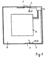
- Fig. 1 shows an access protection device for a walk-in, lockable space area R of a mechanical plant A (this includes, for example, machines or components for manufacturing, treating or processing and existing and possibly also chemical plants or the like) to understand.
- the room area R is accessible via several doors 1 as movable parts relative to fixed walls 2 as a fixed part.
- the optionally circumferentially sealed doors 1 can be opened or closed by pivoting or sliding.
- a controller C is provided, which is coupled to the mechanical system A and the safety sensors S1, S2 to the tumblers Z according to the operating state of the machine system A to open the doors 1 to release or lock.
- the controller C When the controller C is signaled a standstill of the moving parts of the mechanical system A about standstill monitor (not shown), it releases the tumblers Z, so that the space area R by opening the doors 1 is accessible. If at least parts of the mechanical system A do not stand still or are provisions otherwise to be made before the doors 1 are opened, the tumblers are blocked, so that the doors 1 can not be opened. In addition, the controller C prevents commissioning of the mechanical system A at least one open door. 1
- the respective tumbler Z comprises an electromagnet with a coil 3 and a substantially U-shaped core 4, wherein the magnetic circuit formed can be closed by a yoke 5 attached to the door 1.
- a current control 6 The current flowing through the coil 3 and thus the locking force of the tumbler Z is held by a current control 6 at a substantially constant first setpoint. Via the current control 6, a transistor 7 is controlled, via which a correspondingly regulated current flows through the coil 3 and via a shunt 8 to earth. Parallel to the coil 3, a diode 9 is connected, the function of which is to maintain the current through the coil 3 when the transistor 7 turns off.
- the voltage at the shunt 8 is a measure of the current flowing through the coil 3 current. This voltage is represented by an A / D converter 10.
- the current control 6 is periodically, ie after predetermined time intervals, switched to a second setpoint value via a switching signal generated, for example, by the control C.
- This second set point is preferably higher than the first setpoint value, so that the clamping force is not lowered by the switching becomes.
- the switching signal causes the triggering of a counter 11.
- the changeover to the setpoint increase (or decrease) causes due to inductance change of the coil 3 according to an e-function a time delay of reaching the second setpoint, the time to reach the second setpoint by the by the coil 3 flowing current is dependent on the distance at which the yoke 5 is located from the core 4 of the coil 3 and closes the magnetic circuit.
- Upon reaching the second setpoint of the current count of the counter 11 is evaluated to determine and thus to monitor whether the magnetic circuit and thus the tumbler Z is closed with the predetermined clamping force or open, that is, the predetermined clamping force is exceeded.
- a jump S to a level P2 takes place, by which a control jump to the second setpoint So2 is effected.
- the jump S is also the trigger signal for the counter 11.
- the induced inductance change of the coil 3 causes the setpoint So2 is reached only after a time delay.
- a relatively fast reaching of the second setpoint So2 corresponding to the curve piece A occurs after a period T2, which may be, for example, of the order of about 1 ms. If there is a gap between the core 4 and the yoke 5, the setpoint value So2 is reached later according to the curve piece B1, B2..., The time interval depending on the distance of the yoke from the core 4.
- the periodicity with respect to the control jump may, for example, be in the range of 10 to 100 ms or even lower and higher.
- the current control 6, the A / D converter 10 and the counter 11 as well as the evaluation can be represented by a microprocessor.
Landscapes
- Engineering & Computer Science (AREA)
- General Engineering & Computer Science (AREA)
- Mechanical Engineering (AREA)
- Physics & Mathematics (AREA)
- Electromagnetism (AREA)
- Lock And Its Accessories (AREA)
- Control Of Linear Motors (AREA)
- Power-Operated Mechanisms For Wings (AREA)
Claims (8)
- Dispositif de contrôle d'accès à un local, à activation et désactivation commandées, comprenant une partie fixe (2), au moins une partie mobile (1) pour la fermeture d'une ouverture d'accès que comporte ladite partie fixe (2) ainsi que pour chaque partie mobile (1) un moyen de maintien en position fermée (Z) avec un électro-aimant, lequel peut être refermé avec une culasse (5) magnétisable disposée sur ladite partie mobile (1), où l'électro-aimant forme avec la culasse (5) un circuit magnétique fermable par la culasse (5), circuit dont la force de maintien est réglable par une régulation de courant (6) dudit dispositif de contrôle d'accès à un local, caractérisé en ce qu'une première valeur théorique et une deuxième valeur théorique de la régulation de courant (6) sont pré-définies, et que périodiquement un saut de régulation est effectué de la première valeur théorique à la deuxième valeur théorique, lors duquel saut le temps depuis le début du saut jusqu'à l'atteinte est mesuré et dépouillé, pour évaluer si le circuit magnétique et de ce fait le moyen de maintien en position fermée dépasse vers le bas une force de maintien pré-déterminée.
- Dispositif selon la revendication 1, caractérisé en ce que le courant circulant à travers l'électro-aimant est mesurable sur la tension d'un shunt (8) adjacent.
- Dispositif selon la revendication 1 ou 2, caractérisé en ce qu'un compteur (11) est déclenché lors du saut de régulation, et que la position de ce compteur est dépouillable lors de l'atteinte de la deuxième valeur théorique.
- Dispositif selon l'une des revendications 1 à 3, caractérisé en ce que la régulation de courant (6), la mesure du temps et le dépouillement des valeurs sont implantés sur un microprocesseur.
- Moyen de maintien en position fermée avec un électro-aimant comportant une bobine (3) avec un noyau (4), qui est refermable avec une culasse (5) magnétisable, où l'électro-aimant forme avec la culasse (5) un circuit magnétique fermable par la culasse (5), circuit dont la force de maintien est réglable par une régulation de courant (6) dudit moyen de maintien en position fermée, caractérisé en ce que qu'une première valeur théorique et une deuxième valeur théorique de la régulation de courant (6) sont pré-définies, et que périodiquement un saut de régulation est effectué de la première valeur théorique à la deuxième valeur théorique, lors duquel saut le temps depuis le début du saut jusqu'à l'atteinte est mesuré et dépouillé, pour évaluer si le circuit magnétique et de ce fait le moyen de maintien en position fermée dépasse vers le bas une force de maintien pré-déterminée.
- Moyen de maintien en position fermée selon la revendication 5, caractérisé en ce que le courant circulant à travers l'électro-aimant est mesurable sur la tension d'un shunt (8) adjacent.
- Moyen de maintien en position fermée selon la revendication 5 ou 6, caractérisé en ce qu'un compteur (11) est déclenché lors du saut de régulation, et que la position de ce compteur est dépouillable lors de l'atteinte de la deuxième valeur théorique.
- Moyen de maintien en position fermée selon l'une des revendications 5 à 7, caractérisé en ce que la régulation de courant (6), la mesure du temps et le dépouillement des valeurs sont implantés sur un microprocesseur.
Applications Claiming Priority (2)
| Application Number | Priority Date | Filing Date | Title |
|---|---|---|---|
| DE10339363 | 2003-08-27 | ||
| DE10339363A DE10339363B4 (de) | 2003-08-27 | 2003-08-27 | Zugangsschutzeinrichtung für einen Raumbereich |
Publications (3)
| Publication Number | Publication Date |
|---|---|
| EP1510639A2 EP1510639A2 (fr) | 2005-03-02 |
| EP1510639A3 EP1510639A3 (fr) | 2007-08-15 |
| EP1510639B1 true EP1510639B1 (fr) | 2010-04-28 |
Family
ID=34089207
Family Applications (1)
| Application Number | Title | Priority Date | Filing Date |
|---|---|---|---|
| EP04019462A Expired - Lifetime EP1510639B1 (fr) | 2003-08-27 | 2004-08-17 | Dispositif de contrôle d'accès pour un local |
Country Status (4)
| Country | Link |
|---|---|
| US (1) | US7545620B2 (fr) |
| EP (1) | EP1510639B1 (fr) |
| JP (1) | JP3994097B2 (fr) |
| DE (2) | DE10339363B4 (fr) |
Families Citing this family (7)
| Publication number | Priority date | Publication date | Assignee | Title |
|---|---|---|---|---|
| DE102005032172A1 (de) * | 2005-07-09 | 2007-01-11 | K.A. Schmersal Holding Kg | Zuhaltung für ein Bauteil zum Verschließen einer Öffnung |
| EP1862624B1 (fr) * | 2006-06-01 | 2017-02-15 | Pilz Auslandsbeteiligungen GmbH | Dispositif de maintien pour un dispositif de protection de l'accès |
| ATE433035T1 (de) * | 2006-06-01 | 2009-06-15 | Pilz Auslandsbeteiligungen Gmb | Überwachbare zuhalteeinrichtung |
| US8699200B2 (en) * | 2010-02-05 | 2014-04-15 | Honeywell International Inc. | Secure non-contact switch |
| US8456792B2 (en) * | 2010-02-05 | 2013-06-04 | Honeywell International Inc. | Secure non-contact switch |
| WO2017201190A1 (fr) | 2016-05-18 | 2017-11-23 | Shanghai Yanfeng Jinqiao Automotive Trim Systems Co. Ltd | Ensemble console pour intérieur de véhicule |
| US11572723B2 (en) | 2019-02-27 | 2023-02-07 | Shanghai Yanfeng Jinqiao Automotive Triim Systems Co. Ltd. | Vehicle interior component |
Family Cites Families (11)
| Publication number | Priority date | Publication date | Assignee | Title |
|---|---|---|---|---|
| CH672383A5 (fr) * | 1986-10-29 | 1989-11-15 | Baumer Electric Ag | |
| US5198764A (en) * | 1991-02-22 | 1993-03-30 | Sentech Corp. | Position detector apparatus and method utilizing a transient voltage waveform processor |
| US5166729A (en) * | 1991-08-30 | 1992-11-24 | Xerox Corporation | Toner concentration sensing apparatus |
| US5184855A (en) * | 1991-12-23 | 1993-02-09 | Von Duprin, Inc. | Electromagnetic door lock assembly |
| US5942892A (en) | 1997-10-06 | 1999-08-24 | Husco International, Inc. | Method and apparatus for sensing armature position in direct current solenoid actuators |
| DE19910497A1 (de) * | 1999-03-10 | 2000-09-14 | Bosch Gmbh Robert | Lagemessung eines in einer Magnetspule betätigten Magnetankers |
| US6271751B1 (en) * | 1999-08-24 | 2001-08-07 | Securitron Magnalock Corp. | Magnetic lock and status detection system and method therefor |
| JP3292179B2 (ja) * | 1999-09-07 | 2002-06-17 | トヨタ自動車株式会社 | モータ駆動装置のための異常検出装置 |
| DE19953898C5 (de) * | 1999-11-10 | 2004-07-01 | K.A. Schmersal Gmbh & Co | Zugangsschutzeinrichtung |
| DE10141835C2 (de) * | 2001-08-27 | 2003-09-04 | Siemens Ag | Vorrichtung zum Verriegeln von wenigstens zwei Schutztüren einer Industriemaschine |
| DE20306708U1 (de) * | 2003-04-29 | 2003-07-03 | K.A. Schmersal Gmbh & Co, 42279 Wuppertal | Zugangsschutzeinrichtung |
-
2003
- 2003-08-27 DE DE10339363A patent/DE10339363B4/de not_active Expired - Fee Related
-
2004
- 2004-08-03 US US10/911,140 patent/US7545620B2/en not_active Expired - Lifetime
- 2004-08-17 DE DE502004011091T patent/DE502004011091D1/de not_active Expired - Lifetime
- 2004-08-17 JP JP2004236989A patent/JP3994097B2/ja not_active Expired - Fee Related
- 2004-08-17 EP EP04019462A patent/EP1510639B1/fr not_active Expired - Lifetime
Also Published As
| Publication number | Publication date |
|---|---|
| US7545620B2 (en) | 2009-06-09 |
| DE10339363A1 (de) | 2005-03-24 |
| JP2005069479A (ja) | 2005-03-17 |
| US20050047054A1 (en) | 2005-03-03 |
| JP3994097B2 (ja) | 2007-10-17 |
| EP1510639A3 (fr) | 2007-08-15 |
| EP1510639A2 (fr) | 2005-03-02 |
| DE10339363B4 (de) | 2011-02-03 |
| DE502004011091D1 (de) | 2010-06-10 |
Similar Documents
| Publication | Publication Date | Title |
|---|---|---|
| EP2760774B1 (fr) | Dispositif et procédé destinés à la surveillance de portes palières | |
| EP1526239B1 (fr) | Fermeture de sécurité magnétique pour un dispositif de protection mobile | |
| EP3128220B1 (fr) | Système de sécurité | |
| DE102009037036A1 (de) | Zuhaltung zum Verschließen einer Öffnung | |
| DE10339363B4 (de) | Zugangsschutzeinrichtung für einen Raumbereich | |
| WO2018219504A1 (fr) | Dispositif de reconnaissance de position d'étage d'une installation d'ascenseur et procédé destiné à produire un signal d'étage | |
| DE19959233B4 (de) | Induktiver Sensor zum Erfassen von Metallteilen | |
| EP3346177B1 (fr) | Dispositif de sécurité | |
| EP3004717B1 (fr) | Porte d'ascenseur dotée d'un commutateur de contact de porte | |
| EP1862624B1 (fr) | Dispositif de maintien pour un dispositif de protection de l'accès | |
| DE69926455T2 (de) | Schlüsselsicherheitsschalter | |
| EP1473511B1 (fr) | Dispositif de protection d'accès | |
| DE102008055685B4 (de) | Vorrichtung zum Überwachen des Zustandes einer Schutzeinrichtung einer Maschine | |
| DE10333537B4 (de) | Überwachungsvorrichtung mit einem elektronischen programmierbaren System | |
| EP0450399B1 (fr) | Coffre-fort, notamment coffret, à commande à distance électrique | |
| DE102005032172A1 (de) | Zuhaltung für ein Bauteil zum Verschließen einer Öffnung | |
| EP1087279B1 (fr) | Procédé pour la détermination automatique de la vitesse de collision d'une porte d'ascenseur contre un obstacle | |
| DE4142079C2 (de) | Fadenwächter für die Überwachung der Fadenspannung an Textilmaschinen | |
| DE102019216463A1 (de) | Türwächter | |
| EP1956284B1 (fr) | Procédé et dispositif destinés à la sécurisation d'au moins une personne se trouvant dans une zone de danger | |
| EP2843167B1 (fr) | Procédé de commande d'une serrure de véhicule | |
| DE4113665A1 (de) | Fremdfeldsichere kontaktanordnung fuer magnetisch betaetigte naeherungsschalter | |
| EP0478834B1 (fr) | Appareil d'indication de position ouverte ou fermée d'éléments à fermer | |
| DE10042355C1 (de) | Einrichtung zur Positionserfassung einer bewegbaren Einheit, insbesondere für eine Einrichtung zur Berechtigungsidentifizierung und Auslösung/Freigabe einer Aktion für Kraftfahrzeuge | |
| EP4563780A1 (fr) | Disposition d'une porte et procédure de fonctionnement de la disposition |
Legal Events
| Date | Code | Title | Description |
|---|---|---|---|
| PUAI | Public reference made under article 153(3) epc to a published international application that has entered the european phase |
Free format text: ORIGINAL CODE: 0009012 |
|
| AK | Designated contracting states |
Kind code of ref document: A2 Designated state(s): AT BE BG CH CY CZ DE DK EE ES FI FR GB GR HU IE IT LI LU MC NL PL PT RO SE SI SK TR |
|
| AX | Request for extension of the european patent |
Extension state: AL HR LT LV MK |
|
| PUAL | Search report despatched |
Free format text: ORIGINAL CODE: 0009013 |
|
| AK | Designated contracting states |
Kind code of ref document: A3 Designated state(s): AT BE BG CH CY CZ DE DK EE ES FI FR GB GR HU IE IT LI LU MC NL PL PT RO SE SI SK TR |
|
| AX | Request for extension of the european patent |
Extension state: AL HR LT LV MK |
|
| 17P | Request for examination filed |
Effective date: 20071121 |
|
| AKX | Designation fees paid |
Designated state(s): DE FR GB IT |
|
| 17Q | First examination report despatched |
Effective date: 20081107 |
|
| RTI1 | Title (correction) |
Free format text: ACCESS CONTROL DEVICE FOR A ROOM SPACE |
|
| GRAP | Despatch of communication of intention to grant a patent |
Free format text: ORIGINAL CODE: EPIDOSNIGR1 |
|
| GRAS | Grant fee paid |
Free format text: ORIGINAL CODE: EPIDOSNIGR3 |
|
| GRAA | (expected) grant |
Free format text: ORIGINAL CODE: 0009210 |
|
| AK | Designated contracting states |
Kind code of ref document: B1 Designated state(s): DE FR GB IT |
|
| REG | Reference to a national code |
Ref country code: GB Ref legal event code: FG4D Free format text: NOT ENGLISH |
|
| REF | Corresponds to: |
Ref document number: 502004011091 Country of ref document: DE Date of ref document: 20100610 Kind code of ref document: P |
|
| PLBI | Opposition filed |
Free format text: ORIGINAL CODE: 0009260 |
|
| 26 | Opposition filed |
Opponent name: EUCHNER GMBH + CO. KG Effective date: 20110126 |
|
| PLAX | Notice of opposition and request to file observation + time limit sent |
Free format text: ORIGINAL CODE: EPIDOSNOBS2 |
|
| PLAF | Information modified related to communication of a notice of opposition and request to file observations + time limit |
Free format text: ORIGINAL CODE: EPIDOSCOBS2 |
|
| PLBB | Reply of patent proprietor to notice(s) of opposition received |
Free format text: ORIGINAL CODE: EPIDOSNOBS3 |
|
| REG | Reference to a national code |
Ref country code: DE Ref legal event code: R100 Ref document number: 502004011091 Country of ref document: DE |
|
| PLAB | Opposition data, opponent's data or that of the opponent's representative modified |
Free format text: ORIGINAL CODE: 0009299OPPO |
|
| PLCK | Communication despatched that opposition was rejected |
Free format text: ORIGINAL CODE: EPIDOSNREJ1 |
|
| R26 | Opposition filed (corrected) |
Opponent name: EUCHNER GMBH + CO. KG Effective date: 20110126 |
|
| PLBN | Opposition rejected |
Free format text: ORIGINAL CODE: 0009273 |
|
| STAA | Information on the status of an ep patent application or granted ep patent |
Free format text: STATUS: OPPOSITION REJECTED |
|
| 27O | Opposition rejected |
Effective date: 20150518 |
|
| REG | Reference to a national code |
Ref country code: FR Ref legal event code: PLFP Year of fee payment: 13 |
|
| REG | Reference to a national code |
Ref country code: FR Ref legal event code: PLFP Year of fee payment: 14 |
|
| REG | Reference to a national code |
Ref country code: FR Ref legal event code: PLFP Year of fee payment: 15 |
|
| PGFP | Annual fee paid to national office [announced via postgrant information from national office to epo] |
Ref country code: IT Payment date: 20220825 Year of fee payment: 19 Ref country code: GB Payment date: 20220823 Year of fee payment: 19 |
|
| PGFP | Annual fee paid to national office [announced via postgrant information from national office to epo] |
Ref country code: FR Payment date: 20220823 Year of fee payment: 19 |
|
| PGFP | Annual fee paid to national office [announced via postgrant information from national office to epo] |
Ref country code: DE Payment date: 20221027 Year of fee payment: 19 |
|
| P01 | Opt-out of the competence of the unified patent court (upc) registered |
Effective date: 20230524 |
|
| REG | Reference to a national code |
Ref country code: DE Ref legal event code: R119 Ref document number: 502004011091 Country of ref document: DE |
|
| GBPC | Gb: european patent ceased through non-payment of renewal fee |
Effective date: 20230817 |
|
| PG25 | Lapsed in a contracting state [announced via postgrant information from national office to epo] |
Ref country code: GB Free format text: LAPSE BECAUSE OF NON-PAYMENT OF DUE FEES Effective date: 20230817 |
|
| PG25 | Lapsed in a contracting state [announced via postgrant information from national office to epo] |
Ref country code: IT Free format text: LAPSE BECAUSE OF NON-PAYMENT OF DUE FEES Effective date: 20230817 Ref country code: GB Free format text: LAPSE BECAUSE OF NON-PAYMENT OF DUE FEES Effective date: 20230817 Ref country code: FR Free format text: LAPSE BECAUSE OF NON-PAYMENT OF DUE FEES Effective date: 20230831 Ref country code: DE Free format text: LAPSE BECAUSE OF NON-PAYMENT OF DUE FEES Effective date: 20240301 |