EP1510490B1 - Sammelbehälter für Gegenstände - Google Patents
Sammelbehälter für Gegenstände Download PDFInfo
- Publication number
- EP1510490B1 EP1510490B1 EP04255120A EP04255120A EP1510490B1 EP 1510490 B1 EP1510490 B1 EP 1510490B1 EP 04255120 A EP04255120 A EP 04255120A EP 04255120 A EP04255120 A EP 04255120A EP 1510490 B1 EP1510490 B1 EP 1510490B1
- Authority
- EP
- European Patent Office
- Prior art keywords
- tray
- back stop
- catch bin
- pivoting
- objects
- Prior art date
- Legal status (The legal status is an assumption and is not a legal conclusion. Google has not performed a legal analysis and makes no representation as to the accuracy of the status listed.)
- Expired - Lifetime
Links
- 238000000034 method Methods 0.000 claims description 6
- 238000012986 modification Methods 0.000 description 4
- 230000004048 modification Effects 0.000 description 4
- 238000004519 manufacturing process Methods 0.000 description 1
Images

Classifications
-
- B—PERFORMING OPERATIONS; TRANSPORTING
- B65—CONVEYING; PACKING; STORING; HANDLING THIN OR FILAMENTARY MATERIAL
- B65H—HANDLING THIN OR FILAMENTARY MATERIAL, e.g. SHEETS, WEBS, CABLES
- B65H31/00—Pile receivers
- B65H31/04—Pile receivers with movable end support arranged to recede as pile accumulates
- B65H31/08—Pile receivers with movable end support arranged to recede as pile accumulates the articles being piled one above another
- B65H31/10—Pile receivers with movable end support arranged to recede as pile accumulates the articles being piled one above another and applied at the top of the pile
-
- B—PERFORMING OPERATIONS; TRANSPORTING
- B65—CONVEYING; PACKING; STORING; HANDLING THIN OR FILAMENTARY MATERIAL
- B65H—HANDLING THIN OR FILAMENTARY MATERIAL, e.g. SHEETS, WEBS, CABLES
- B65H31/00—Pile receivers
- B65H31/34—Apparatus for squaring-up piled articles
- B65H31/36—Auxiliary devices for contacting each article with a front stop as it is piled
Definitions
- This invention relates in general to an object catch bin and, more particularly, to an object catch bin that pivots.
- Object catch bins are used to stack objects. Often, catch bins are used to catch compact discs after the discs have been printed. In many standard object catch bins, newly printed discs are dropped directly on top of one another. This direct impact may scratch or nick newly printed discs or objects already in the bin. Additionally, the conventional direct impact object catch bin usually leaves the stacked objects or discs in a non-uniform stack.
- catch bin rests entirely on springs. Although this type of catch bin may effectively cushion the impact of objects dropping directly on one another, this type of catch bin utilizes a significant amount of space and is expensive to manufacture.
- a further catch bin is shown in GB 939 288 A.
- an object catch bin has a tray disposed to catch objects.
- the tray is pivotal about an edge. Bias means resist pivoting of the tray.
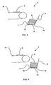
- Figures 1-3 are illustrations of one embodiment of the object catch bin of the present invention in operation.
- Figure 4 illustrates another embodiment of the object catch bin of the present invention.
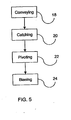
- Figure 5 is a flow chart illustrating one embodiment of the method for stacking objects of the present invention.
- Object catch bin 2 includes a tray 4.
- Tray 4 is disposed to catch objects 6.
- Tray 4 is made of any material and has any shape suitable for holding object 6.
- Object 6 is any object that is stackable. Examples of object 6 include compact discs, disc cases, cassettes, and boxes.
- Back stop 8 is any structure capable of catching object 6 in tray 4. In one embodiment, back stop 8 is integral with tray 4. In another embodiment, back stop 8 is not integral with tray 4. Back stop 8 is attached to tray 4 in one embodiment and not attached to tray 4 in another embodiment. Optionally, tray 4 rests on a base member 14. Base member 14 can have any shape or configuration suitable for supporting or holding tray 4. In one embodiment, base member 14 is attached to back stop 8. In another embodiment, base member 14 is detached from back stop 8.
- Tray 4 has an edge 10. In one embodiment of tray 4, edge 10 is located at the vertex of tray 4 and back stop 8. Tray 4 is pivotal about edge 10 of tray 4.
- Bias means 12 is any structure that causes tray 4 to resist pivoting about edge 10 of tray 4. Examples of bias means 12 are springs, hydraulics, and magnetic bias means. In one embodiment, bias means 12 is attached only to tray 4. In another embodiment, bias means 12 is disposed between tray 4 and base member 14.
- Conveyor means 16 is any device for projecting objects 6 into tray 4. Examples of conveyor means 16 include conveyor belts, rollers, and slides.
- Pivoting of tray 4 about edge 10 of tray 4 serves to cushion the impact of object 6 on tray 4 after object 6 is projected into tray 4 by conveyor means 16.
- Tray 4 optionally pivots using a hinge. Pivoting of tray 4 also optionally results in rotation of tray 4 to a desired location depending on the weight and contents of tray 4. For example, as illustrated in figures 1 through 3, as the number or weight of objects 6 on tray 4 increase, tray 4 pivots from an angled position (figure 1) to a mostly horizontal position (figure 3) when full.
- Figure 4 illustrates pivoting in another embodiment of the configuration of tray 4 and back stop 8.
- tray 4 and back stop 8 are attached to each other at edge 10. Both tray 4 and back stop 8 pivot about edge 10 of tray 4. As the number or weight of objects 6 on tray 4 increases, tray 4 pivots from an angled position to a mostly horizontal position and back stop 8 pivots from an angled position to a mostly vertical position. The mostly vertical position of back stop 8 facilitates straight stacking of objects 6.
- Figure 5 is a flow chart representing steps of one embodiment of the present invention. Although the steps represented in Figure 5 are presented in a specific order, the present invention encompasses variations in the order of steps. Furthermore, additional steps may be executed between the steps illustrated in Figure 5 without departing from the scope of the present invention.
- Object 6 is conveyed 18 into tray 4.
- Tray 4 catches 20 object 6.
- Catching 20 includes receiving the object 6 after it is conveyed 18 into the tray 4.
- Bias means 12 bias 24 tray 4 to resist pivoting about edge 10 of tray 4.
- bias means 12 may be selected to resist pivoting regardless of the weight and contents of tray 4.
- bias means 12 may be selected to modify the degree of resistance based upon the weight and contents of tray 4. Modification of the degree of resistance of the bias means 12 allows tray 4 to pivot 22 to a desired location. For example, bias means 12 allows tray 4 to pivot 22 from angled when empty to horizontal when full.
Landscapes
- Engineering & Computer Science (AREA)
- Mechanical Engineering (AREA)
- Pile Receivers (AREA)
- Packaging Frangible Articles (AREA)
Claims (10)
- Ein Objektauffangbehälter (2), der folgende Merkmale aufweist:(a) einen rückwärtigen Anschlag (8);(b) eine Ablage (4), die winklig zu dem rückwärtigen Anschlag (8) angeordnet ist, und dadurch gekennzeichnet, dass die Ablage (4) um den Scheitel der Ablage (4) und des rückwärtigen Anschlags (8) schwenkbar ist; und durch(c) eine Vorspannungseinrichtung (12), um sich dem Schwenken der Ablage (4) zu widersetzen.
- Der Objektauffangbehälter (2) gemäß Anspruch 1, bei dem die Ablage (4) und der rückwärtige Anschlag (8) relativ zueinander fest sind.
- Der Objektauffangbehälter (2) gemäß Anspruch 1, bei dem der rückwärtige Anschlag (8) um den Scheitel der Ablage (4) und des rückwärtigen Anschlags (8) schwenkbar ist.
- Der Objektauffangbehälter (2) gemäß Anspruch 1, der ferner ein Basisbauglied (14) zum Halten der Ablage (4) aufweist.
- Der Objektauffangbehälter (2) gemäß Anspruch 1, der ferner ein Gelenk, das an der Ablage (4) angebracht ist, zum Schwenken der Ablage (4) um den Scheitel der Ablage (4) und des rückwärtigen Anschlags (8) umfasst.
- Der Objektauffangbehälter (2) gemäß Anspruch 1, der ferner eine Fördereinrichtung (16) zum Werfen eines Objekts in die Ablage (4) umfasst.
- Ein Verfahren zum Stapeln von Objekten (6), wobei das Verfahren folgende Schritte aufweist:(a) Fördern (18) von Objekten (6);(b) Auffangen (20) der Objekte (6) mit einer Ablage (4);(c) Schwenken (22) der Ablage (4);(d) Vorspannen (24) der Ablage (4), um sich dem Schwenken zu widersetzen.
- Das Verfahren gemäß Anspruch 7, bei dem das Vorspannen (24) der Ablage (4) ein federbares Widersetzen gegen ein Schwenken umfasst.
- Das Verfahren gemäß Anspruch 7, bei dem das Vorspannen (24) der Ablage (4) ein hydraulisches Widersetzen gegen ein Schwenken umfasst.
- Das Verfahren gemäß Anspruch 7, bei dem das Vorspannen (24) der Ablage (4) ein magnetisches Widersetzen gegen ein Schwenken umfasst.
Applications Claiming Priority (2)
| Application Number | Priority Date | Filing Date | Title |
|---|---|---|---|
| US649146 | 2003-08-27 | ||
| US10/649,146 US20050047900A1 (en) | 2003-08-27 | 2003-08-27 | Object catch bin |
Publications (2)
| Publication Number | Publication Date |
|---|---|
| EP1510490A1 EP1510490A1 (de) | 2005-03-02 |
| EP1510490B1 true EP1510490B1 (de) | 2006-06-14 |
Family
ID=34104674
Family Applications (1)
| Application Number | Title | Priority Date | Filing Date |
|---|---|---|---|
| EP04255120A Expired - Lifetime EP1510490B1 (de) | 2003-08-27 | 2004-08-25 | Sammelbehälter für Gegenstände |
Country Status (3)
| Country | Link |
|---|---|
| US (1) | US20050047900A1 (de) |
| EP (1) | EP1510490B1 (de) |
| DE (1) | DE602004001183D1 (de) |
Family Cites Families (22)
| Publication number | Priority date | Publication date | Assignee | Title |
|---|---|---|---|---|
| US705998A (en) * | 1898-08-05 | 1902-07-29 | Clarence W Hobbs | Adjustable receiving-table for scoring-machines. |
| US1773977A (en) * | 1929-03-28 | 1930-08-26 | American Bank Note Co | Sheet-delivery machine |
| US2658630A (en) * | 1947-08-23 | 1953-11-10 | Thomas N Melin | Lumber stacking device |
| US2636933A (en) * | 1949-11-21 | 1953-04-28 | Allis Chalmers Mfg Co | Control system responsive to presence of magnetic materials |
| US3046010A (en) * | 1960-02-04 | 1962-07-24 | Eureka Specialty Printing Co | Stacker apparatus |
| GB939288A (en) * | 1962-03-14 | 1963-10-09 | Eureka Specialt Printing Compa | Improvements in or relating to a stacking apparatus |
| US3655183A (en) * | 1970-07-13 | 1972-04-11 | Xerox Corp | Sheet feed apparatus |
| AU468611B2 (en) * | 1971-06-04 | 1976-01-15 | Canon Kabushiki Kaisha | Automatic cut sheet feeding unit |
| US3772972A (en) * | 1972-03-20 | 1973-11-20 | Taylor M L | Stacker |
| US3937456A (en) * | 1974-09-26 | 1976-02-10 | Fairchild Industries, Inc. | Article stacking apparatus |
| DE3022619C2 (de) * | 1980-06-16 | 1985-01-03 | Herbert Kannegiesser Gmbh + Co, 4973 Vlotho | Stapelgerät zum Aufeinanderstapeln textiler Flächengebilde o.dgl. |
| US4577853A (en) * | 1984-01-16 | 1986-03-25 | Harris Graphics Corporation | Stacking apparatus |
| JPS63218453A (ja) * | 1987-03-05 | 1988-09-12 | Fuji Photo Film Co Ltd | 画像記録装置 |
| US5183248A (en) * | 1989-08-28 | 1993-02-02 | Mita Industrial Co., Ltd. | Sheet feeding device |
| US5558318A (en) * | 1991-01-15 | 1996-09-24 | Roll Systems, Inc. | Separator for forming discrete stacks of folded web |
| US5085421A (en) * | 1991-03-04 | 1992-02-04 | Compaq Computer Corporation | Dual bin paper feed tray for an image reproduction machine such as a printer or copier |
| FR2675487B1 (fr) * | 1991-04-18 | 1993-07-16 | Komori Chambon | Appareil d'empilage, par le dessus, d'articles minces et plats, tels que des flans de carton. |
| US6364309B1 (en) * | 1999-08-30 | 2002-04-02 | Brother Kogyo Kabushiki Kaisha | Sheet accommodating device |
| US6631902B1 (en) * | 2000-03-30 | 2003-10-14 | Hewlett-Packard Development Company, L.P. | Media storage bin and method of using same |
| KR100388996B1 (ko) * | 2000-12-30 | 2003-06-25 | 삼성전자주식회사 | 화상형성장치의 용지 카세트 |
| JP4756751B2 (ja) * | 2001-02-27 | 2011-08-24 | キヤノン株式会社 | シート積載装置とこの装置を備えたシート後処理装置および画像形成装置 |
| KR100412497B1 (ko) * | 2001-11-12 | 2003-12-31 | 삼성전자주식회사 | 프린팅기기의 용지 카세트 |
-
2003
- 2003-08-27 US US10/649,146 patent/US20050047900A1/en not_active Abandoned
-
2004
- 2004-08-25 EP EP04255120A patent/EP1510490B1/de not_active Expired - Lifetime
- 2004-08-25 DE DE602004001183T patent/DE602004001183D1/de not_active Expired - Lifetime
Also Published As
| Publication number | Publication date |
|---|---|
| DE602004001183D1 (de) | 2006-07-27 |
| US20050047900A1 (en) | 2005-03-03 |
| EP1510490A1 (de) | 2005-03-02 |
Similar Documents
| Publication | Publication Date | Title |
|---|---|---|
| US10967405B2 (en) | Systems and methods for high throughput sorting | |
| US9014844B2 (en) | Methods and apparatus for stacking receptacles in materials handling facilities | |
| US8231002B2 (en) | Mailpiece container for stacking mixed mail and method for stacking mail therein | |
| US6714834B1 (en) | Flats bundle processing system | |
| US11639279B2 (en) | System for transferring articles from a container | |
| CN114537961A (zh) | 使用盒子托盘组件动态处理物体的系统和方法 | |
| EP1510490B1 (de) | Sammelbehälter für Gegenstände | |
| US20140003903A1 (en) | Package stacking apparatus | |
| US7029225B2 (en) | Stacking tray for flat mail items | |
| EP0850865A2 (de) | Kassette/Schubladevorrichtung zur aufnahme von Dokumenten | |
| EP0571874B1 (de) | Vorrichtung zum Stapeln von flachen Gegenständen zur Bildung von einem oder mehreren Stapeln in einem kastenförmigen Behälter | |
| US20070090590A1 (en) | Vertical mail piece stacker | |
| US6012566A (en) | Means and method for conveyance of individual objects | |
| US3144248A (en) | Tray and bracket for paper sorting | |
| US6666450B2 (en) | Swing gate | |
| US7713017B2 (en) | Method and device for unloading stacked mailpieces | |
| EP0428968A1 (de) | Einstellbare Dokumenten-Aufbewahrungsvorrichtung für einen Dokumenten-Sortierer | |
| US20060163791A1 (en) | Collating stacker and method of use | |
| JPH0719245U (ja) | 書籍の積み重ね収納装置 | |
| JPS5895067A (ja) | 紙葉類群収容用トレイの昇降装置 | |
| US20080226433A1 (en) | Method and system for extracting sorted mail items in mail processing systems | |
| FR2901719A1 (fr) | Systeme de tri d'objets plats par intercalaires amovibles et independants sur caisse normalisee |
Legal Events
| Date | Code | Title | Description |
|---|---|---|---|
| PUAI | Public reference made under article 153(3) epc to a published international application that has entered the european phase |
Free format text: ORIGINAL CODE: 0009012 |
|
| AK | Designated contracting states |
Kind code of ref document: A1 Designated state(s): AT BE BG CH CY CZ DE DK EE ES FI FR GB GR HU IE IT LI LU MC NL PL PT RO SE SI SK TR |
|
| AX | Request for extension of the european patent |
Extension state: AL HR LT LV MK |
|
| 17P | Request for examination filed |
Effective date: 20050428 |
|
| AKX | Designation fees paid |
Designated state(s): DE FR GB |
|
| GRAP | Despatch of communication of intention to grant a patent |
Free format text: ORIGINAL CODE: EPIDOSNIGR1 |
|
| GRAS | Grant fee paid |
Free format text: ORIGINAL CODE: EPIDOSNIGR3 |
|
| GRAA | (expected) grant |
Free format text: ORIGINAL CODE: 0009210 |
|
| AK | Designated contracting states |
Kind code of ref document: B1 Designated state(s): DE FR GB |
|
| REG | Reference to a national code |
Ref country code: GB Ref legal event code: FG4D |
|
| REF | Corresponds to: |
Ref document number: 602004001183 Country of ref document: DE Date of ref document: 20060727 Kind code of ref document: P |
|
| PG25 | Lapsed in a contracting state [announced via postgrant information from national office to epo] |
Ref country code: DE Free format text: LAPSE BECAUSE OF FAILURE TO SUBMIT A TRANSLATION OF THE DESCRIPTION OR TO PAY THE FEE WITHIN THE PRESCRIBED TIME-LIMIT Effective date: 20060915 |
|
| PLBE | No opposition filed within time limit |
Free format text: ORIGINAL CODE: 0009261 |
|
| STAA | Information on the status of an ep patent application or granted ep patent |
Free format text: STATUS: NO OPPOSITION FILED WITHIN TIME LIMIT |
|
| EN | Fr: translation not filed | ||
| 26N | No opposition filed |
Effective date: 20070315 |
|
| PG25 | Lapsed in a contracting state [announced via postgrant information from national office to epo] |
Ref country code: FR Free format text: LAPSE BECAUSE OF FAILURE TO SUBMIT A TRANSLATION OF THE DESCRIPTION OR TO PAY THE FEE WITHIN THE PRESCRIBED TIME-LIMIT Effective date: 20070309 |
|
| PG25 | Lapsed in a contracting state [announced via postgrant information from national office to epo] |
Ref country code: FR Free format text: LAPSE BECAUSE OF FAILURE TO SUBMIT A TRANSLATION OF THE DESCRIPTION OR TO PAY THE FEE WITHIN THE PRESCRIBED TIME-LIMIT Effective date: 20060614 |
|
| PGFP | Annual fee paid to national office [announced via postgrant information from national office to epo] |
Ref country code: GB Payment date: 20120828 Year of fee payment: 9 |
|
| GBPC | Gb: european patent ceased through non-payment of renewal fee |
Effective date: 20130825 |
|
| PG25 | Lapsed in a contracting state [announced via postgrant information from national office to epo] |
Ref country code: GB Free format text: LAPSE BECAUSE OF NON-PAYMENT OF DUE FEES Effective date: 20130825 |