EP1510435A2 - Lenksäule und Verstellverfahren für eine Lenksäule - Google Patents
Lenksäule und Verstellverfahren für eine Lenksäule Download PDFInfo
- Publication number
- EP1510435A2 EP1510435A2 EP04021210A EP04021210A EP1510435A2 EP 1510435 A2 EP1510435 A2 EP 1510435A2 EP 04021210 A EP04021210 A EP 04021210A EP 04021210 A EP04021210 A EP 04021210A EP 1510435 A2 EP1510435 A2 EP 1510435A2
- Authority
- EP
- European Patent Office
- Prior art keywords
- load
- steering column
- occupant
- bolt
- devices
- Prior art date
- Legal status (The legal status is an assumption and is not a legal conclusion. Google has not performed a legal analysis and makes no representation as to the accuracy of the status listed.)
- Granted
Links
Images



Classifications
-
- B—PERFORMING OPERATIONS; TRANSPORTING
- B62—LAND VEHICLES FOR TRAVELLING OTHERWISE THAN ON RAILS
- B62D—MOTOR VEHICLES; TRAILERS
- B62D1/00—Steering controls, i.e. means for initiating a change of direction of the vehicle
- B62D1/02—Steering controls, i.e. means for initiating a change of direction of the vehicle vehicle-mounted
- B62D1/16—Steering columns
- B62D1/18—Steering columns yieldable or adjustable, e.g. tiltable
- B62D1/19—Steering columns yieldable or adjustable, e.g. tiltable incorporating energy-absorbing arrangements, e.g. by being yieldable or collapsible
- B62D1/195—Yieldable supports for the steering column
-
- F—MECHANICAL ENGINEERING; LIGHTING; HEATING; WEAPONS; BLASTING
- F16—ENGINEERING ELEMENTS AND UNITS; GENERAL MEASURES FOR PRODUCING AND MAINTAINING EFFECTIVE FUNCTIONING OF MACHINES OR INSTALLATIONS; THERMAL INSULATION IN GENERAL
- F16F—SPRINGS; SHOCK-ABSORBERS; MEANS FOR DAMPING VIBRATION
- F16F7/00—Vibration-dampers; Shock-absorbers
- F16F7/12—Vibration-dampers; Shock-absorbers using plastic deformation of members
- F16F7/127—Vibration-dampers; Shock-absorbers using plastic deformation of members by a blade element cutting or tearing into a quantity of material; Pultrusion of a filling material
Definitions
- the invention relates to a steering column according to the preamble of claim 1 and an adjustment for a steering column according to the preamble of claim 6.
- a vehicle steering column which is adjusted in the event of an accident so that at least the steering wheel end of a Inmates move away.
- the present invention aims to provide this steering column and its adjustment method for To further improve the protection of the occupants.
- a steering column for a vehicle is provided with adjusting devices, which are triggered in the event of an accident to at least one steering wheel end to move the steering column away from an occupant, with the adjustment devices for damping a movement of at least the steering wheel end portion of the steering column of a Inmates away include load-bearing devices that depend on occupant parameters are controllable, and wherein the load receiving means at least one load receiver contained, which is set by an adjustable bolt out of action.
- the adjusting devices Drive means for effecting the movement of at least the steering wheel end portion
- the drive means contain a pyrotechnic gas generator and / or electrically triggered are.
- the adjusting devices load receiving devices for damping a movement of at least the steering wheel end portion of the steering column of a Inmates away, and that the load-bearing devices in the event of an accident operated by the controller in dependence on the occupant parameters directly or indirectly are.
- the load-bearing devices contain at least two levels, in case of an accident depending on the control are operable directly or indirectly by the occupant parameters, preferably the stages of the load-receiving devices individually with in particular each different Load-bearing properties and / or simultaneously with added load-bearing properties are operable.
- the load-receiving devices or, if applicable, each step individually in the event of an accident, depending on the controller can be switched off directly or indirectly from the occupant parameters. More with these Designs combinable features are that the load-bearing devices or optionally a stage thereof deformation means, in particular along a path of movement cutting blades and / or material deforming bolts, and / or braking devices, in particular a brake slide with preferably at least two braking force levels, included.
- the controller may preferably be for triggering the drive means depending on the seating position of the occupant and in particular for Detecting a predefinable distance or below a predetermined distance the position of the seat for the occupant of the steering wheel by means of the detection means be designed.
- the control for Triggering such an operating mode of the adjusting is designed, in which in Case of an accident at a detected predetermined distance or a detected underrun a predetermined distance of the position of the seat for the occupant from the steering wheel Drive devices of the adjusting devices are triggered.
- the control for operating the load receiving devices or possibly each step thereof individually depending on the AngurtSh and / or the Seating position of the occupant is designed, the control in particular for triggering a such operating mode of the adjusting is designed, in which case in the event of an accident in a non-belted occupant, the load-bearing devices or at least one Level of which are / is effective.
- the controller for triggering a be designed in such an operating mode of the adjustment, wherein in the case of Accident at a detected predetermined distance or a detected drop below a predeterminable distance of the position of the seat for the occupant from the steering wheel, the load-bearing devices or at least one stage of which is / are ineffective.
- the detection devices position detection devices the seat for the occupant, condition detecting devices of the belt buckle for the seat belt the occupant, height, weight and / or posture detection devices with respect to the occupant.
- the position detection devices the seat for the occupant in particular at least one electrical or optical Contain switch in or in connection with seat guide rails, and / or the condition detection devices of the buckle for the seat belt of the occupant at least contain an electrical or optical lock switch.
- the above-mentioned object of the present invention is also achieved with an adjustment method achieved for a steering column of a vehicle, with adjusting devices in the case an accident are triggered to at least one steering wheel end of the steering column to move away from an occupant, wherein the adjusting devices by means of load-receiving devices, which are controllable in dependence on occupant parameters, a movement at least the steering wheel end portion of the steering column away from an occupant, and wherein the load-receiving devices are controlled to operate in dependence on occupant parameters at least one load receiver contained therein by an adjustable bolt out of function.
- a drive of the adjusting devices for effecting the movement at least the steering wheel end portion of the steering column away from the occupant in the event of an accident triggered in response to the occupant parameters and / or movement at least of the steering wheel end portion of the steering column away from an occupant in the event of an accident in Dependence on the occupant parameters muted.
- the latter method variant is at least a damping of the movement of the steering wheel end portion of the steering column away from an occupant in the event of an accident in Depending on the occupant parameters in particular optionally switched off in individual stages.
- the seating position, the garter condition, the size, the weight and / or the posture of the occupant as occupant parameters is / will be detected. It is preferred that the adjustment in Depending on the seating position of the occupant are driven, in particular the Adjustment devices in the event of an accident at a detected predetermined distance or a detected falls below a predetermined distance of the position of the seat for the occupant are not driven by the steering wheel according to an operating mode. Alternatively or In addition, the adjustment depending on the AngurtMap and / or be damped from the seating position of the occupant.
- the adjustment in the event of an accident in a non-belted occupant be attenuated in whole or in part according to an operating mode and / or the adjusting devices in the case of an accident at a specified predetermined distance or a detected falls below a predetermined distance of the position of the seat for the occupant be wholly or partially attenuated by the steering wheel according to an operating mode.
- the present invention thus provides a steering column and an adjustment method for a steering column according to the above-mentioned earlier applications in an advantageous manner further improved.
- the first embodiment is thus a double parallel load limiting provided, in combination with unbeltung large persons the high load degrades.
- unbelted heavy drivers is a much larger load bearing necessary, as it is common in practice today.
- Today's known from practice safety steering columns are for example in a "slide” (see Figs. 1, 2, 3a, 3b, 3c and 4 and associated description) stored. This "sled” moves when exceeding one structurally fixed load limit against a deforming sheet, which according to the present invention, the high load peak in heavy drivers with two load receivers A and B is dismantled.
- the weight recognition of the tall driver and the position detection e.g. a small one
- drivers can also use electronic weight and position sensors that are currently available be developed in many places, or to other suitable, the skilled person readily known or accessible species are determined.
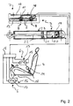
- Fig. 2 schematically illustrates the circuit diagram of the first embodiment.
- An indicated only steering column 1 for a vehicle has a conventional Telescopic structure, due to its notoriety in numerous embodiments will not be discussed here, since the present invention in all known Embodiments also total retractable, not telescopically fauxschiebbarer Apply steering columns and the present invention is not the actual design relates to such steering columns.
- the steering column 1 has a steering wheel end portion 2 and is equipped with adjusting devices 3, which are triggered in the event of an accident to at least the Steering wheel end portion 2 of the steering column 1 to move away from an occupant (not shown), sitting on a seat 4.
- the adjusting devices 3 are illustrated for the three in the figure Operating modes designed.
- a controller 5 detects by means of detection means 6 occupant parameters and triggers an operating mode of the vehicle depending on the occupant parameters Adjustment 3 off.
- the adjusting devices 3 include load receiving devices 7 with a first and a second load receiver or limiter 8 (A) and 9 (B), each with its own bolt 10 and 11 and a common load-bearing plate 12, the deformation devices Form (D). By the bolts 10 and 11, the load-bearing plate 12 with a Carriage 13 connected.
- the load-bearing plate 12 is provided with a telescopic part (not shown) the steering column 1 firmly connected, and the carriage 13 is connected to the other telescopic part (not shown) of the steering column 1 firmly connected.
- the bolts 10 and 11 each have an explosive charge S supplied by the controller 5, for example, which is connected to or integrated in an overall control (not shown) for an airbag, each independently electrically ignited, to make each of the bolts 10 and 11 ineffective.
- To the controller 5 are as detection devices 6 state detection devices 13 of a buckle 14 in Form of a belt or lock switch 15 connected. This belt usage switch 15 results in a belt usage signal when the occupant is wearing his seatbelt (not shown) created according to the regulations. If the Gurtgardssignal not generated, so is the Inform the driver that the occupant is not wearing the seatbelt properly.
- the detection devices 6 contain position-recognition devices 16, which are formed by a position switch 17 in a seat rail 18 of the seat 4.
- This position switch 17 results in a near position signal when the seat 4 is in the position of the position switch 17 has reached or closer than the position switch 17 on the steering column 1 is.
- the controller 5 receives the information that the occupant is one small person acts. If the near position signal is not generated, the controller is over it informed that the inmate is a big person.
- the controller 5 If the controller 5 has received the near position signal, it causes the operating mode for a strapped or unbelted "little woman". In this mode the controller ignites 5 the explosive charges S of the two bolts 10 and 11, so that they are ineffective and the load-bearing plate 12 and the carriage 13 are decoupled. Further ignites the controller 5 is a pyrotechnic explosive 19 of a gas generator 20, and generated by this Gas acts on a piston 21 with a piston rod 22 adjacent to the steering wheel end portion 2 containing telescopic part (not shown) of the steering column 1 firmly connected is that the two telescopic parts (not shown) of the steering column 5 are contracted. The parts 19 to 22 are components of the adjustment 3 and form together Drive devices 23.
- the controller 5 If the controller 5 has not received the near-position signal, it checks to see if the belt-use signal given is. If the Gurtgardssignal before, then causes the controller 5 the Operating mode for a strapped "big man". In this mode the controller ignites 5 the explosive charge S only of the bolt 11, so that only this is ineffective and the Load bearing plate 12 and the carriage 13 are still coupled by the bolt 10. Of the Loader 8 (A) is thus effective to dissipate energy, which is at the impact of the belted "big man” on the steering wheel (not labeled) occurs. The drive devices 23 are not triggered.
- the controller 5 causes the operation mode for an unbelted "big man".
- the controller 5 ignites no explosive charge S, so that the load-bearing plate 12 and the carriage 13 are coupled by both bolts 10 and 11.
- the load receptor 8 (A) and the load receptor 9 (B) are thus effective to dissipate energy during the Impact of unbuttled "big man” on the steering wheel (not labeled) occurs.
- the drive means 23 are not triggered.
- FIGS. 3a, 3b and 3c show a carriage 13 for receiving the steering (not shown) in FIG its slide receptacle 24 in Fig. 3a left from below and right from above and in the Fig. 3b and 3c respectively cut.
- the pyrotechnic gas generator 20 of the drive means 23 is attached on the one hand to the carriage receptacle 24 and on the other hand on the carriage 13.
- the load receivers 8 and 9 are on the one hand with the bolts 10 and 11 on the carriage 13 and on the other hand on the carriage holder 24 with screw connections 25 provided.
- the sliding telescopic part (not shown) of the steering column 1 is in the Recess L firmly mounted.
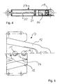
- the drive means 23 are shown separately in FIG. 4, as already related were explained with the Fig. 2.
- Fig. 5 shows above, i. in a ready-to-install state, and below after an actuation both load receiver 8 and 9, the load-bearing plate 12, in which it is a stamped part is.
- the invention thus according to the first embodiment in particular a safety steering column created with a crash carriage, which has two load carriers, for belted and unbelted large and small persons.
- a control with a lock switch is a control with a lock switch.
- the crash carriage for the small persons as a "distance carriage" used and his loader are taken out of service.
- a statement Small persons can preferably be done via an electric seat position detection.
- the load receiver such are built consecutively, e.g. by means of a slot in a connection, to delayed start-up, that the load pickups add up to the load.
- this embodiment relates to a safety steering column with pyrotechnic powered shortening for small drivers and peak load reduction for tall drivers.
- Steering columns are partly in addition to an airbag already with a load tip reduction equipped for heavy persons.
- Practice has also shown that small and too tight Driver positioned on the airbag will partially die as a result of this.
- the second embodiment also provides a solution for load peak removal in large drivers and in the same system a steering column shortening in small drivers in an accident.
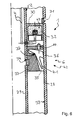
- Figs. 6 to 8 show a steering column outer tube 28 and a steering column inner tube 29, the Represent telescopic parts of a steering column 1, wherein the steering column inner tube 29, the steering wheel end 2 of the steering column 1 contains.
- On the steering column outer tube 28 is an outer tube annular piston 30, for example, by a Verclinchtagen 31 attached.
- the outer tube ring piston 30 contains a pyrotechnic cartridge 32, with control cables K to the controller 5 (see Fig. 2) is connected.
- the steering column inner tube 29 is an inner tube annular piston 33 firmly connected by also a Verclinchitati 34.
- This inner tube ring piston 33 includes one or more in slots in the second embodiment 35 stored, appropriately shaped cutting blade 36 as parts of deformation devices 6.
- the cutting blade 36 are mounted on a "tipping point" 37 so that they at Drive via the inner tube annular piston 33 targeted into the wall 38 of the steering column outer tube 28 of the steering column 1 cut.
- the cutting depth 39 of the chip 40 is replaced by a correspondingly shaped stop 41 is determined.
- the size of Spanes 40 is proportional to desired load absorption.
- the deformation devices 6 form load receptacles 42.
- the outer tube annular piston 30 and the inner tube annular piston 33 form drive devices 23, as well as the load receptacles 42 components of the adjusting 3 of the Steering column 1 are.
- Fig. 8 shows a corresponding load bearing 42 in function.
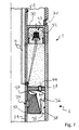
- Fig. 7 shows the function of small drivers.
- the charge 43 pushes the pyrotechnic Cartridge 32, the inner tube annular piston 33 connected to the steering column inner tube 29th down and thus away from an occupant (not shown).
- the pressure control pin 44 tilting the Schneidemessers 36 in the position "Load picking", i. for chip removal in the wall 38 of the steering column outer tube 28 the steering column 1.
- ring piston Into telescopic steering column tubes are provided with "ring piston", the small drivers shorten the steering column with a pyrotechnic pressure build-up between them and to bring an inflating airbag to a greater distance.
- a load-bearing mechanism is installed, which is used by tall drivers instead of the steering column shortening becomes effective and with small drivers by pyrotechnic pressure except Function is set.
- the second ring piston is provided with a load receiving mechanism.
- load receiving mechanism In the example shown are appropriately shaped and stored tiltable Knife. It can also be here corrugated pipes, material-deforming balls or similar. act (in not shown in the figures).
- the function of the load-bearing ring piston such that it automatically picks up and breaks down load when the inner steering column tube is relative is moved to the outside.
- the knife is machined into the outer Steering column tube pressed.
- this load absorption in a pyrotechnic ignition be "dubbed” with appropriate performance, or will the "knife” as in the example tilted out of function by a pressurized control pin.
- the inner and outer steering column tubes are designed for the largest possible difference in diameter.
- the outer steering column tube is positioned in bearings (not shown in the figures).
- the inner Steering column tube is to the outer positive fit with corresponding annular piston (grooves / shape) connected.
- the ring piston pair is e.g. by clinching with one outer and one each connected to the inner tube.
- An annular piston contains a pyrotechnic charge whose pressure Press the ring pistons away from each other and thus shorten the steering column or the steering wheel in the direction of travel to pull away from the occupant.
- Small drivers can also be detected in the second embodiment, e.g. by appropriate electronic monitoring systems or a seat position detection by means of switches in the seat rail.
Landscapes
- Engineering & Computer Science (AREA)
- Mechanical Engineering (AREA)
- General Engineering & Computer Science (AREA)
- Chemical & Material Sciences (AREA)
- Combustion & Propulsion (AREA)
- Transportation (AREA)
- Steering Controls (AREA)
- Air Bags (AREA)
Abstract
Description
- Der wenigstens eine Lastaufnehmer ist durch Entriegelung seiner Befestigung mit dem verstellbaren Bolzen ausser Funktion setzbar.
- Der wenigstens eine Lastaufnehmer ist in Abhängigkeit von Insassenparametern steuerbar mit dem verstellbaren Bolzen ausser Funktion setzbar.
- Die Lastaufnahmeeinrichtungen sind für wenigstens zwei Betriebsmodi ausgelegt, wobei vorzugsweise eine Steuerung zum Erfassen von Insassenparametern mittels Detektionseinrichtungen und zum Auslösen eines Betriebsmodus der Verstelleinrichtungen in Abhängigkeit von den Insassenparametern vorgesehen ist.
- Die Verstellung eines Bolzens macht diesen Bolzen unwirksam.
- Der Bolzen ist mittels eines Elektromagneten verstellbar.
- Der verstellbare Bolzen ist ein pyrotechnisch entriegelbarer Bolzen, wobei der Bolzen vorzugsweise über eine Sprengladung verfügt, die insbesondere ggf. von der Steuerung und/oder elektrisch zündbar ist.
- Die Lastaufnahmeeinrichtungen enthalten wenigstens zwei Lastaufnehmer, die durch jeweils einen verstellbaren Bolzen getrennt ausser Funktion setzbar sind.
- Die Lastaufnahmeeinrichtungen enthalten wenigstens zwei Lastaufnehmer, die jeweils getrennt und auch gleichzeitig ausser Funktion setzbar sind oder gleichzeitig in Funktion bleiben können, so dass die Lastaufnahmewirkungen von wenigstens zwei Lastaufnehmem addiert sind.
- Die Lastaufnahmeeinrichtungen enthalten wenigstens zwei Lastaufnehmer enthalten, die einstückig ausgeführt sind.
- Jeder Lastaufnehmer enthält ein Lastaufnahmeblech.
- Wenigstens zwei Lastaufnehmer enthalten ein gemeinsames Lastaufnahmeblech,
wobei vorzugsweise
das Lastaufnahmeblech ein Stanzteil ist, das insbesondere Reisslinien (26) enthält, und/oder
wobei mit Vorzug- die Lenksäule zwei Teleskopteile enthält, von denen dasjenige, das einen Lenkrad-Endbereich enthält, durch Belastung durch einen auf das Lenkrad auftreffenden Insassen in oder über das andere Teleskopteil geschoben wird, und
- jedes oder das Lastaufnahmeblech mit einem Schlitten, der mit einem Teleskopteil der Lenksäule fest verbunden ist, durch den/die Bolzen lösbar verbunden ist und mit dem anderen Teleskopteil der Lenksäule fest verbunden ist,
durch Verstellen eines Bolzens dieser Bolzen wirkungslos wird und das Lastaufnahmeblech und der Schlitten entkoppelt sind.
- Der wenigstens eine Lastaufnehmer wird durch Entriegelung seiner Befestigung mit dem verstellbaren Bolzen ausser Funktion gesetzt.
- Der wenigstens eine Lastaufnehmer wird in Abhängigkeit von Insassenparametern steuerbar mit dem verstellbaren Bolzen ausser Funktion gesetzt.
- Die Lastaufnahmeeinrichtungen sind für wenigstens zwei Betriebsmodi ausgelegt, wobei vorzugsweise eine Steuerung zum Erfassen von Insassenparametern mittels Detektionseinrichtungen und zum Auslösen eines Betriebsmodus der Verstelleinrichtungen in Abhängigkeit von den Insassenparametern betrieben wird.
- Die Verstellung eines Bolzens macht diesen Bolzen unwirksam.
- Der Bolzen wird mittels eines Elektromagneten verstellt.
- Der verstellbare Bolzen wird pyrotechnisch entriegelt wird, wobei der Bolzen vorzugsweise über eine Sprengladung verfügt, die insbesondere ggf. von der Steuerung und/oder elektrisch gezündet wird.
- Die Lastaufnahmeeinrichtungen enthalten wenigstens zwei Lastaufnehmer, die durch jeweils einen verstellbaren Bolzen getrennt ausser Funktion gesetzt werden.
- Die Lastaufnahmeeinrichtungen enthalten wenigstens zwei Lastaufnehmer, die jeweils getrennt oder auch gleichzeitig ausser Funktion gesetzt werden oder gleichzeitig in Funktion bleiben, so dass die Lastaufnahmewirkungen von wenigstens zwei Lastaufnehmem addiert wirken.
- Die Lastaufnahmeeinrichtungen enthalten wenigstens zwei Lastaufnehmer, die einstükkig ausgeführt sind.
- Jeder Lastaufnehmer enthält ein Lastaufnahmeblech.
- Wenigstens zwei Lastaufnehmer enthalten ein gemeinsames Lastaufnahmeblech.
- Das Lastaufnahmeblech ist ein Stanzteil, das insbesondere Reisslinien enthält.
- Die Lenksäule enthält zwei Teleskopteile, von denen dasjenige, das einen Lenkrad-Endbereich enthält, durch Belastung durch einen auf das Lenkrad auftreffenden Insassen in oder über das andere Teleskopteil geschoben wird, und jedes oder das Lastaufnahmeblech mit einem Schlitten, der mit einem Teleskopteil der Lenksäule fest verbunden ist, durch den/die Bolzen lösbar verbunden ist und mit dem anderen Teleskopteil der Lenksäule fest verbunden ist,
- Fig. 1
- zeigt schematisch Betriebsmodi von Verstelleinrichtungen eines ersten Ausführungsbeispiels einer Lenksäule,
- Fig. 2
- zeigen schematisch ein Schalt- und Aufbauschema der Steuerung des ersten Ausführungsbeispiels der Lenksäule von Fig. 1,
- Fig. 3a, 3b und 3c
- zeigen schematisch die Verstelleinrichtungen des ersten Ausführungsbeispiels der Lenksäule von Fig. 1 in einer Ansicht von unten (linke Hälfte von Fig. 3a) und oben (rechte Hälfte von Fig. 3a) bzw. entsprechende Querschnitte,
- Fig. 4
- zeigen schematisch die Antriebseinrichtungen des ersten Ausführungsbeispiels der Lenksäule von Fig. 1,
- Fig. 5
- zeigen schematisch die Lastaufnahmeeinrichtungen des ersten Ausführungsbeispiels der Lenksäule von Fig. 1, und
- Fig. 6 bis 8
- zeigen schematisch in einer Querschnittsansicht ein zweites Ausführungsbeispiel einer Lenksäule vor einer Auslösung, nach einer Auslösung bei einem kleinen Insassen bzw. nach einer Auslösung bei einem grossen.
Claims (10)
- Lenksäule für ein Fahrzeug, mit Verstelleinrichtungen (3), die im Falle eines Unfalls auslösbar sind, um zumindest einen Lenkrad-Endbereich (2) der Lenksäule (1) von einem Insassen weg zu bewegen, wobei die Verstelleinrichtungen (3) zum Dämpfen einer Bewegung zumindest des Lenkrad-Endbereiches (2) der Lenksäule (1) von einem Insassen weg Lastaufnahmeeinrichtungen (7) enthalten, die in Abhängigkeit von Insassenparametern steuerbar sind,
dadurch gekennzeichnet, dass die Lastaufnahmeeinrichtungen (7) wenigstens einen Lastaufnehmer (8, 9) enthalten, der durch einen verstellbaren Bolzen (10, 11) ausser Funktion setzbar ist. - Lenksäule nach Anspruch 1,
dadurch gekennzeichnet, dass der wenigstens eine Lastaufnehmer (8, 9) durch Entriegelung seiner Befestigung mit dem verstellbaren Bolzen (10, 11) ausser Funktion setzbar ist, und/oder
dass der wenigstens eine Lastaufnehmer (8, 9) in Abhängigkeit von Insassenparametern steuerbar mit dem verstellbaren Bolzen (10, 11) ausser Funktion setzbar ist, und/oder
dass die Lastaufnahmeeinrichtungen (7) für wenigstens zwei Betriebsmodi ausgelegt sind, wobei vorzugsweise eine Steuerung (5) zum Erfassen von Insassenparametern mittels Detektionseinrichtungen (6) und zum Auslösen eines Betriebsmodus der Verstelleinrichtungen (3) in Abhängigkeit von den Insassenparametern vorgesehen ist. - Lenksäule nach Anspruch 1 oder 2,
dadurch gekennzeichnet, dass die Verstellung eines Bolzens (10, 11) diesen Bolzen (10, 11) unwirksam macht, und/oder
dass der Bolzen mittels eines Elektromagneten verstellbar ist, oder
dass der verstellbare Bolzen ein pyrotechnisch entriegelbarer Bolzen (10, 11) ist, wobei der Bolzen (10, 11) vorzugsweise über eine Sprengladung (S) verfügt, die insbesondere ggf. von der Steuerung (5) und/oder elektrisch zündbar ist. - Lenksäule nach einem der vorhergehenden Ansprüche,
dadurch gekennzeichnet, dass die Lastaufnahmeeinrichtungen (7) wenigstens zwei Lastaufnehmer (8, 9) enthalten, die durch jeweils einen verstellbaren Bolzen (10, 11) getrennt ausser Funktion setzbar sind, und/oder
dass die Lastaufnahmeeinrichtungen (7) wenigstens zwei Lastaufnehmer (8, 9) enthalten, die jeweils getrennt und auch gleichzeitig ausser Funktion setzbar sind oder gleichzeitig in Funktion bleiben können, so dass die Lastaufnahmewirkungen von wenigstens zwei Lastaufnehmern (8, 9) addiert sind, und/oder
dass die Lastaufnahmeeinrichtungen (7) wenigstens zwei Lastaufnehmer (8, 9) enthalten, die einstückig ausgeführt sind. - Lenksäule nach einem der vorhergehenden Ansprüche,
dadurch gekennzeichnet, dass jeder Lastaufnehmer (8, 9) ein Lastaufnahmeblech (12) enthält, oder dass wenigstens zwei Lastaufnehmer (8, 9) ein gemeinsames Lastaufnahmeblech (12) enthalten,
wobei vorzugsweise
das Lastaufnahmeblech (12) ein Stanzteil ist, das insbesondere Reisslinien (26) enthält, und/oder
wobei mit Vorzugund wobei weiter bevorzugtdie Lenksäule (1) zwei Teleskopteile enthält, von denen dasjenige, das einen Lenkrad-Endbereich (2) enthält, durch Belastung durch einen auf das Lenkrad auftreffenden Insassen in oder über das andere Teleskopteil geschoben wird, undjedes oder das Lastaufnahmeblech (12) mit einem Schlitten (13), der mit einem Teleskopteil der Lenksäule 1 fest verbunden ist, durch den/die Bolzen (10, 11) lösbar verbunden ist und mit dem anderen Teleskopteil der Lenksäule (1) fest verbunden ist,
durch Verstellen eines Bolzens (10, 11) dieser Bolzen (10, 11) wirkungslos wird und das Lastaufnahmeblech (12) und der Schlitten (13) entkoppelt sind. - Verstellverfahren für eine Lenksäule für ein Fahrzeug, mit Verstelleinrichtungen (3), die im Falle eines Unfalls ausgelöst werden, um zumindest einen Lenkrad-Endbereich (2) der Lenksäule (1) von einem Insassen weg zu bewegen, wobei die Verstelleinrichtungen (3) mittels Lastaufnahmeeinrichtungen (7), die in Abhängigkeit von Insassenparametern steuerbar sind, eine Bewegung zumindest des Lenkrad-Endbereiches (2) der Lenksäule (1) von einem Insassen weg dämpfen,
dadurch gekennzeichnet, dass die Lastaufnahmeeinrichtungen (7) gesteuert werden, um in Abhängigkeit von Insassenparametern wenigstens einen darin enthaltenen Lastaufnehmer (8, 9) durch einen verstellbaren Bolzen (10, 11) ausser Funktion zu setzen. - Verstellverfahren nach Anspruch 6,
dadurch gekennzeichnet, dass der wenigstens eine Lastaufnehmer (8, 9) durch Entriegelung seiner Befestigung mit dem verstellbaren Bolzen (10, 11) ausser Funktion gesetzt wird, und/oder
dass der wenigstens eine Lastaufnehmer (8, 9) in Abhängigkeit von Insassenparametern steuerbar mit dem verstellbaren Bolzen (10, 11) ausser Funktion gesetzt wird, und/oder dass die Lastaufnahmeeinrichtungen (7) für wenigstens zwei Betriebsmodi ausgelegt sind, wobei vorzugsweise eine Steuerung (5) zum Erfassen von Insassenparametern mittels Detektionseinrichtungen (6) und zum Auslösen eines Betriebsmodus der Verstelleinrichtungen (3) in Abhängigkeit von den Insassenparametern betrieben wird. - Verstellverfahren nach Anspruch 6 oder 7,
dadurch gekennzeichnet, dass die Verstellung eines Bolzens (10, 11) diesen Bolzen (10, 11) unwirksam macht, und/oder
dass der Bolzen mittels eines Elektromagneten verstellt wird, oder
dass der verstellbare Bolzen (10, 11) pyrotechnisch entriegelt wird, wobei der Bolzen (10, 11) vorzugsweise über eine Sprengladung (S) verfügt, die insbesondere ggf. von der Steuerung (5) und/oder elektrisch gezündet wird. - Verstellverfahren nach einem der Ansprüche 6 bis 8,
dadurch gekennzeichnet, dass die Lastaufnahmeeinrichtungen (7) wenigstens zwei Lastaufnehmer (8, 9) enthalten, die durch jeweils einen verstellbaren Bolzen (10, 11) getrennt ausser Funktion gesetzt werden, und/oder
dass die Lastaufnahmeeinrichtungen (7) wenigstens zwei Lastaufnehmer (8, 9) enthalten, die jeweils getrennt und auch gleichzeitig ausser Funktion gesetzt werden oder gleichzeitig in Funktion bleiben, so dass die Lastaufnahmewirkungen von wenigstens zwei Lastaufnehmern (8, 9) addiert wirken, und/oder
dass die Lastaufnahmeeinrichtungen (7) wenigstens zwei Lastaufnehmer (8, 9) enthalten, die einstückig ausgeführt sind. - Verstellverfahren nach einem der Ansprüche 6 bis 9,
dadurch gekennzeichnet, dass jeder Lastaufnehmer (8, 9) ein Lastaufnahmeblech (12) enthält, oder dass wenigstens zwei Lastaufnehmer (8, 9) ein gemeinsames Lastaufnahmeblech (12) enthalten,
wobei vorzugsweise
das Lastaufnahmeblech (12) ein Stanzteil ist, das insbesondere Reisslinien (26) enthält, und/oder
wobei mit Vorzugund wobei weiter bevorzugtdie Lenksäule (1) zwei Teleskopteile enthält, von denen dasjenige, das einen Lenkrad-Endbereich (2) enthält, durch Belastung durch einen auf das Lenkrad auftreffenden Insassen in oder über das andere Teleskopteil geschoben wird, undjedes oder das Lastaufnahmeblech (12) mit einem Schlitten (13), der mit einem Teleskopteil der Lenksäule 1 fest verbunden ist, durch den/die Bolzen (10, 11) lösbar verbunden ist und mit dem anderen Teleskopteil der Lenksäule (1) fest verbunden ist,
durch Verstellen eines Bolzens (10, 11) dieser Bolzen (10, 11) wirkungslos wird und das Lastaufnahmeblech (12) und der Schlitten (13) entkoppelt sind.
Applications Claiming Priority (5)
| Application Number | Priority Date | Filing Date | Title |
|---|---|---|---|
| DE29910058U | 1999-06-09 | ||
| DE29910056 | 1999-06-09 | ||
| DE29910058 | 1999-06-09 | ||
| DE29910056U | 1999-06-09 | ||
| EP00945629A EP1187752B1 (de) | 1999-06-09 | 2000-06-09 | Lenksäule und verstellverfahren für eine lenksäule |
Related Parent Applications (2)
| Application Number | Title | Priority Date | Filing Date |
|---|---|---|---|
| EP00945629.4 Division | 2000-06-09 | ||
| EP00945629A Division EP1187752B1 (de) | 1999-06-09 | 2000-06-09 | Lenksäule und verstellverfahren für eine lenksäule |
Publications (3)
| Publication Number | Publication Date |
|---|---|
| EP1510435A2 true EP1510435A2 (de) | 2005-03-02 |
| EP1510435A3 EP1510435A3 (de) | 2009-09-30 |
| EP1510435B1 EP1510435B1 (de) | 2013-09-25 |
Family
ID=26062564
Family Applications (3)
| Application Number | Title | Priority Date | Filing Date |
|---|---|---|---|
| EP00945629A Expired - Lifetime EP1187752B1 (de) | 1999-06-09 | 2000-06-09 | Lenksäule und verstellverfahren für eine lenksäule |
| EP03017865A Expired - Lifetime EP1384643B1 (de) | 1999-06-09 | 2000-06-09 | Lenksäule und Verstellverfahren für eine Lenksäule |
| EP04021210.2A Expired - Lifetime EP1510435B1 (de) | 1999-06-09 | 2000-06-09 | Lenksäule und Verstellverfahren für eine Lenksäule |
Family Applications Before (2)
| Application Number | Title | Priority Date | Filing Date |
|---|---|---|---|
| EP00945629A Expired - Lifetime EP1187752B1 (de) | 1999-06-09 | 2000-06-09 | Lenksäule und verstellverfahren für eine lenksäule |
| EP03017865A Expired - Lifetime EP1384643B1 (de) | 1999-06-09 | 2000-06-09 | Lenksäule und Verstellverfahren für eine Lenksäule |
Country Status (5)
| Country | Link |
|---|---|
| EP (3) | EP1187752B1 (de) |
| AU (1) | AU5964500A (de) |
| DE (2) | DE50011087D1 (de) |
| ES (3) | ES2440465T3 (de) |
| WO (1) | WO2000076832A1 (de) |
Families Citing this family (5)
| Publication number | Priority date | Publication date | Assignee | Title |
|---|---|---|---|---|
| US6581966B2 (en) * | 2001-01-05 | 2003-06-24 | Ford Global Technologies, Inc. | Twin axis steering wheel system |
| DE50306469D1 (de) * | 2002-05-07 | 2007-03-29 | Thyssenkrupp Presta Ag | Sicherheitslenkung und Betriebsverfahren dafür |
| DE102009009577B3 (de) | 2009-02-19 | 2010-05-27 | Thyssenkrupp Presta Ag | Lenksäule für eine Kraftfahrzeug |
| DE102012100626B3 (de) | 2012-01-25 | 2013-02-21 | Thyssenkrupp Presta Aktiengesellschaft | Lenksäule für ein Kraftfahrzeug |
| DE102012111890B3 (de) | 2012-12-06 | 2013-12-24 | Thyssenkrupp Presta Aktiengesellschaft | Lenksäule für ein Kraftfahrzeug |
Family Cites Families (6)
| Publication number | Priority date | Publication date | Assignee | Title |
|---|---|---|---|---|
| NL7502142A (en) * | 1975-02-21 | 1976-08-24 | Noord Nederlandsche Maschf | Impact-absorbing device for rail vehicle - has telescopic elements of which one cuts into the other on impact |
| JP2776102B2 (ja) * | 1991-12-11 | 1998-07-16 | 日産自動車株式会社 | 車両用安全装置 |
| SE507771C2 (sv) * | 1996-11-21 | 1998-07-13 | Volvo Ab | Anordning och förfarande för skydd av åkande i fordon |
| SE510856C2 (sv) * | 1997-06-23 | 1999-06-28 | Volvo Ab | Kraftupptagande anordning för skydd av åkande i fordon |
| DE19829238A1 (de) * | 1997-06-30 | 1999-01-07 | Volkswagen Ag | Lenkvorrichtung für ein Fahrzeug |
| JP2002514549A (ja) * | 1998-05-11 | 2002-05-21 | イノーヴァ ゲーエムベーハー テクニッシュ エントヴィックルンゲン | 安全ステアリングコラム、自動車の安全システムおよび安全システムを備える自動車ならびに安全方法 |
-
2000
- 2000-06-09 EP EP00945629A patent/EP1187752B1/de not_active Expired - Lifetime
- 2000-06-09 AU AU59645/00A patent/AU5964500A/en not_active Abandoned
- 2000-06-09 ES ES04021210.2T patent/ES2440465T3/es not_active Expired - Lifetime
- 2000-06-09 ES ES03017865T patent/ES2248691T3/es not_active Expired - Lifetime
- 2000-06-09 ES ES00945629T patent/ES2226874T3/es not_active Expired - Lifetime
- 2000-06-09 EP EP03017865A patent/EP1384643B1/de not_active Expired - Lifetime
- 2000-06-09 EP EP04021210.2A patent/EP1510435B1/de not_active Expired - Lifetime
- 2000-06-09 WO PCT/DE2000/001889 patent/WO2000076832A1/de not_active Ceased
- 2000-06-09 DE DE50011087T patent/DE50011087D1/de not_active Expired - Lifetime
- 2000-06-09 DE DE50007693T patent/DE50007693D1/de not_active Expired - Lifetime
Also Published As
| Publication number | Publication date |
|---|---|
| ES2440465T3 (es) | 2014-01-29 |
| EP1187752A1 (de) | 2002-03-20 |
| EP1510435B1 (de) | 2013-09-25 |
| AU5964500A (en) | 2001-01-02 |
| EP1187752B1 (de) | 2004-09-08 |
| EP1384643A2 (de) | 2004-01-28 |
| EP1510435A3 (de) | 2009-09-30 |
| ES2248691T3 (es) | 2006-03-16 |
| EP1384643A3 (de) | 2004-02-04 |
| DE50011087D1 (de) | 2005-10-06 |
| ES2226874T3 (es) | 2005-04-01 |
| WO2000076832A8 (de) | 2001-04-19 |
| DE50007693D1 (de) | 2004-10-14 |
| WO2000076832A1 (de) | 2000-12-21 |
| EP1384643B1 (de) | 2005-08-31 |
Similar Documents
| Publication | Publication Date | Title |
|---|---|---|
| DE19938938B4 (de) | Fahrzeuginsassen-Schutzsystem | |
| DE19847385C1 (de) | Stoßfängeranordnung | |
| DE19931804A1 (de) | Fahrzeuginsassenschutzvorrichtung | |
| DE29805217U1 (de) | Fahrzeuginsassen-Rückhaltesystem | |
| DE102010062550A1 (de) | Insassensicherheitssystem | |
| DE2409159A1 (de) | Sicherheitsgurtsystem fuer ein kraftfahrzeug | |
| EP1016567A2 (de) | Fahrzeugsicherheitsvorrichtung zum Schutz der Füsse des Insassen | |
| DE4330486A1 (de) | Verfahren zur Auslösung eines Airbags in einem Kraftfahrzeug | |
| DE102011122203A1 (de) | Rückhaltevorrichtung für ein Kraftfahrzeug | |
| DE102019210001A1 (de) | Kraftfahrzeug mit einer Ablageeinrichtung | |
| DE102011108918A1 (de) | Rückhaltevorrichtung für ein Kraftfahrzeug | |
| EP1077863B1 (de) | Sicherheitslenksäule, sicherheitssystem für ein fahrzeug und fahrzeug mit einem sicherheitssystem sowie sicherheitsverfahren | |
| DE60130018T2 (de) | Anordnung zur schwächung einer konstruktion | |
| DE60006325T2 (de) | Kraftfahrzeug-Insassenschutzsystem | |
| DE19742584A1 (de) | Luftsackeinrichtung | |
| DE10261870A1 (de) | Kraftfahrzeug mit Vorrichtungen zum Anheben eines Deckels oder Deckelteils bei einer Fußgängerkollision sowie zur Rückführung desselben | |
| DE102022000596A1 (de) | Schutzvorrichtung für einen Kraftwagen, insbesondere für einen Personenkraftwagen | |
| DE602004008322T2 (de) | Sicherheitsanordnung | |
| EP1384643B1 (de) | Lenksäule und Verstellverfahren für eine Lenksäule | |
| DE102004058034A1 (de) | Aktives Kniepolster mit adaptivem Kraftreaktionssystem und -verfahren | |
| DE19904072B4 (de) | Insassenschutzvorrichtung an einem Lenkrad eines Fahrzeugs | |
| DE69700078T2 (de) | Aktive Kontrolle des Insassenkörpers mit einem Rückhaltesystem mit begrenzter Zugkraft während eines Frontalaufpralls | |
| EP1369297B1 (de) | Kraftfahrzeug und Verfahren zur Reduzierung der Belastung von Insassen eines Kraftfahrzeugs bei einem Zusammenstoss mit einem Hindernis | |
| DE10020660A1 (de) | Fahrzeug, insbesondere Kraftfahrzeug | |
| DE102011108915B4 (de) | Rückhaltevorrichtung für ein Kraftfahrzeug |
Legal Events
| Date | Code | Title | Description |
|---|---|---|---|
| PUAI | Public reference made under article 153(3) epc to a published international application that has entered the european phase |
Free format text: ORIGINAL CODE: 0009012 |
|
| AC | Divisional application: reference to earlier application |
Ref document number: 1187752 Country of ref document: EP Kind code of ref document: P |
|
| AK | Designated contracting states |
Kind code of ref document: A2 Designated state(s): DE ES FR GB IT |
|
| PUAL | Search report despatched |
Free format text: ORIGINAL CODE: 0009013 |
|
| AK | Designated contracting states |
Kind code of ref document: A3 Designated state(s): DE ES FR GB IT |
|
| 17P | Request for examination filed |
Effective date: 20100317 |
|
| AKX | Designation fees paid |
Designated state(s): DE ES FR GB IT |
|
| 17Q | First examination report despatched |
Effective date: 20100604 |
|
| GRAP | Despatch of communication of intention to grant a patent |
Free format text: ORIGINAL CODE: EPIDOSNIGR1 |
|
| GRAS | Grant fee paid |
Free format text: ORIGINAL CODE: EPIDOSNIGR3 |
|
| GRAA | (expected) grant |
Free format text: ORIGINAL CODE: 0009210 |
|
| AC | Divisional application: reference to earlier application |
Ref document number: 1187752 Country of ref document: EP Kind code of ref document: P |
|
| AK | Designated contracting states |
Kind code of ref document: B1 Designated state(s): DE ES FR GB IT |
|
| REG | Reference to a national code |
Ref country code: GB Ref legal event code: FG4D Free format text: NOT ENGLISH |
|
| REG | Reference to a national code |
Ref country code: DE Ref legal event code: R096 Ref document number: 50016333 Country of ref document: DE Effective date: 20131121 |
|
| REG | Reference to a national code |
Ref country code: ES Ref legal event code: FG2A Ref document number: 2440465 Country of ref document: ES Kind code of ref document: T3 Effective date: 20140129 |
|
| REG | Reference to a national code |
Ref country code: DE Ref legal event code: R097 Ref document number: 50016333 Country of ref document: DE |
|
| PLBE | No opposition filed within time limit |
Free format text: ORIGINAL CODE: 0009261 |
|
| STAA | Information on the status of an ep patent application or granted ep patent |
Free format text: STATUS: NO OPPOSITION FILED WITHIN TIME LIMIT |
|
| 26N | No opposition filed |
Effective date: 20140626 |
|
| REG | Reference to a national code |
Ref country code: DE Ref legal event code: R097 Ref document number: 50016333 Country of ref document: DE Effective date: 20140626 |
|
| REG | Reference to a national code |
Ref country code: FR Ref legal event code: PLFP Year of fee payment: 16 |
|
| PG25 | Lapsed in a contracting state [announced via postgrant information from national office to epo] |
Ref country code: IT Free format text: LAPSE BECAUSE OF NON-PAYMENT OF DUE FEES Effective date: 20150609 |
|
| PGRI | Patent reinstated in contracting state [announced from national office to epo] |
Ref country code: IT Effective date: 20160711 |
|
| REG | Reference to a national code |
Ref country code: FR Ref legal event code: PLFP Year of fee payment: 17 |
|
| PGFP | Annual fee paid to national office [announced via postgrant information from national office to epo] |
Ref country code: IT Payment date: 20161220 Year of fee payment: 17 |
|
| REG | Reference to a national code |
Ref country code: FR Ref legal event code: PLFP Year of fee payment: 18 |
|
| PG25 | Lapsed in a contracting state [announced via postgrant information from national office to epo] |
Ref country code: IT Free format text: LAPSE BECAUSE OF NON-PAYMENT OF DUE FEES Effective date: 20170609 |
|
| PGFP | Annual fee paid to national office [announced via postgrant information from national office to epo] |
Ref country code: DE Payment date: 20180830 Year of fee payment: 19 |
|
| PGFP | Annual fee paid to national office [announced via postgrant information from national office to epo] |
Ref country code: GB Payment date: 20181219 Year of fee payment: 19 Ref country code: ES Payment date: 20181218 Year of fee payment: 19 Ref country code: FR Payment date: 20181218 Year of fee payment: 19 |
|
| REG | Reference to a national code |
Ref country code: DE Ref legal event code: R119 Ref document number: 50016333 Country of ref document: DE |
|
| GBPC | Gb: european patent ceased through non-payment of renewal fee |
Effective date: 20190609 |
|
| PG25 | Lapsed in a contracting state [announced via postgrant information from national office to epo] |
Ref country code: GB Free format text: LAPSE BECAUSE OF NON-PAYMENT OF DUE FEES Effective date: 20190609 Ref country code: DE Free format text: LAPSE BECAUSE OF NON-PAYMENT OF DUE FEES Effective date: 20200101 |
|
| PG25 | Lapsed in a contracting state [announced via postgrant information from national office to epo] |
Ref country code: FR Free format text: LAPSE BECAUSE OF NON-PAYMENT OF DUE FEES Effective date: 20190630 |
|
| REG | Reference to a national code |
Ref country code: ES Ref legal event code: FD2A Effective date: 20201027 |
|
| PG25 | Lapsed in a contracting state [announced via postgrant information from national office to epo] |
Ref country code: ES Free format text: LAPSE BECAUSE OF NON-PAYMENT OF DUE FEES Effective date: 20190610 |