EP1510412B1 - Überrollbügeleinheit für ein Fahrzeug - Google Patents
Überrollbügeleinheit für ein Fahrzeug Download PDFInfo
- Publication number
- EP1510412B1 EP1510412B1 EP04254626A EP04254626A EP1510412B1 EP 1510412 B1 EP1510412 B1 EP 1510412B1 EP 04254626 A EP04254626 A EP 04254626A EP 04254626 A EP04254626 A EP 04254626A EP 1510412 B1 EP1510412 B1 EP 1510412B1
- Authority
- EP
- European Patent Office
- Prior art keywords
- roll bar
- vehicle
- deployment
- assembly according
- bar assembly
- Prior art date
- Legal status (The legal status is an assumption and is not a legal conclusion. Google has not performed a legal analysis and makes no representation as to the accuracy of the status listed.)
- Expired - Lifetime
Links
- UONOETXJSWQNOL-UHFFFAOYSA-N tungsten carbide Chemical compound [W+]#[C-] UONOETXJSWQNOL-UHFFFAOYSA-N 0.000 claims description 6
- 239000011521 glass Substances 0.000 description 8
- 239000000463 material Substances 0.000 description 6
- 238000010586 diagram Methods 0.000 description 4
- 238000010348 incorporation Methods 0.000 description 4
- 230000003068 static effect Effects 0.000 description 3
- 239000000470 constituent Substances 0.000 description 2
- 239000012634 fragment Substances 0.000 description 2
- 101150071434 BAR1 gene Proteins 0.000 description 1
- 229910000831 Steel Inorganic materials 0.000 description 1
- 208000027418 Wounds and injury Diseases 0.000 description 1
- 230000001133 acceleration Effects 0.000 description 1
- 239000000853 adhesive Substances 0.000 description 1
- 230000001070 adhesive effect Effects 0.000 description 1
- 230000000712 assembly Effects 0.000 description 1
- 238000000429 assembly Methods 0.000 description 1
- 238000002485 combustion reaction Methods 0.000 description 1
- 230000002860 competitive effect Effects 0.000 description 1
- 230000006378 damage Effects 0.000 description 1
- 239000003822 epoxy resin Substances 0.000 description 1
- 239000005357 flat glass Substances 0.000 description 1
- 208000014674 injury Diseases 0.000 description 1
- 238000004806 packaging method and process Methods 0.000 description 1
- 229920000647 polyepoxide Polymers 0.000 description 1
- 239000000843 powder Substances 0.000 description 1
- 230000001681 protective effect Effects 0.000 description 1
- 230000000717 retained effect Effects 0.000 description 1
- 238000005096 rolling process Methods 0.000 description 1
- 239000010959 steel Substances 0.000 description 1
- 239000000725 suspension Substances 0.000 description 1
- 230000001960 triggered effect Effects 0.000 description 1
Images




Classifications
-
- B—PERFORMING OPERATIONS; TRANSPORTING
- B60—VEHICLES IN GENERAL
- B60R—VEHICLES, VEHICLE FITTINGS, OR VEHICLE PARTS, NOT OTHERWISE PROVIDED FOR
- B60R21/00—Arrangements or fittings on vehicles for protecting or preventing injuries to occupants or pedestrians in case of accidents or other traffic risks
- B60R21/02—Occupant safety arrangements or fittings, e.g. crash pads
- B60R21/13—Roll-over protection
Definitions
- This invention relates to roll bar assemblies for vehicles and particularly for convertible motor vehicles having a rear window made of glass.
- GB-A-2157543 discloses a deployable roll bar which pivots from a horizontal stowed position to a vertical deployed position.
- the roll bar is located behind the front seat of a vehicle and is triggered by means of a pyrotechnic device in conjunction with a sensor responsive to vehicle rotational acceleration or angle of rotation.
- US-A-5,458,396 discloses a deployable u-shaped roll bar that is stowed in a retracted position in the headrest or backrest of a seat and which extends upwards above an occupant's head in a deployed position.
- the roll bar's deployment system includes a spring-loaded release member and a hold member so that on deployment, the roll bar may be forced upwards by the action of the spring and locked in an extended position by the hold member.
- GB-A-2,184,586 discloses sensor means for controlling deployment of a roll bar.
- a first sensor comprises an inertia switch located centrally in the vehicle and a second sensor means comprises switches located on the rear wheels of the vehicle, each switch being closed when the rear wheel suspension is completely extended, and a third sensor comprising a tilt switch. This combination of switches facilitates deployment of the roll bar when overturning of the vehicle is imminent and inhibits deployment when the vehicle is lifted in a workshop or is driven over a hump.
- the static or deployed position has to be sufficiently high in order to offer a protective 'zone' in which the occupants are retained, thus avoiding or minimising contact between an occupant's head and the road surface when the vehicle is rolling or static on the ground.
- Deployable roll bars must be able to reach a point where protection is afforded irrespective of the position of the roof, i.e. up or down.
- the present invention provides a roll bar assembly for a vehicle, said assembly including a deployable roll bar incorporating a pin which protrudes from an upper surface of the deployable roll bar for breaking a rear window of the vehicle on deployment of the roll bar.
- the present invention provides a seat for a vehicle, which in said seat is incorporated the roll bar assembly in accordance with said first aspect recited above.
- the present invention provides a vehicle incorporating the roll bar assembly in accordance with said first aspect recited above.
- the present invention provides a vehicle incorporating the seat in accordance with said second aspect recited above.
- the pin has a part which is fixed to and a part which protrudes from the upper surface of the roll bar.
- the pin may be fixed to the upper surface of the roll bar by means of a threaded joint.
- a protruding part of the pin may have a conical, frusto-conical or domed shape. Such shapes have been found to break a glass window satisfactorily, causing it to shatter into small pieces.
- the protruding part of the pin is made from a hard material having a hardness of at least 1000 Vickers, e.g. tungsten carbide.
- the roll bar is provided with an orifice in the upper surface thereof, and the pin is deployable and incorporated in a pyrotechnic actuator, said actuator being located within the roll bar such that on deployment of the actuator, the deployable pin extends through the orifice beyond the upper surface of the roll bar.
- This alternative embodiment is advantageous in that in the stowed, non-deployed position, no protrusion extends from the roll-bar. It also optimises styling freedom through the ability to locate the roof of the vehicle and trim features in lower positions. (The embodiment having fixed, protruding pins requires extra clearance space between the roll bar and vehicle trim). The alternative embodiment is also safer to handle during vehicle assembly and service.
- the pyrotechnic actuator may be fixed to the upper surface of roll bar by means of a threaded joint.
- An upper part of the deployable pin may be conical, frusto-conical or dome shaped.
- An upper part of the deployable pin may be composed of tungsten carbide, or any suitable material having a hardness of at least 1000 Vickers.
- the roll bar assembly may further include spring-loaded means and a solenoid switch for effecting deployment of the roll bar.
- the spring-loaded means may be activated by pyrotechnic means rather than a solenoid switch.
- the roll bar may be actuated pyrotechnically.
- the roll bar and breaking device may be included in the back rest of one or all of the seats of a vehicle and the roll bar may be an inverted u-shape.
- a roll bar and breaking device may be located behind one or all of the seats of the vehicle, or may be positioned behind the seats and extend across the vehicle from one side to the other.
- the roll bar may include just one breaking device preferably located close to an outboard shoulder of the 'U' or two devices, each located close to each shoulder of the 'U'.
- breaking devices ensures that, no matter whether the roll bar is fitted to either a left hand seat or a right hand seat, on deployment, the pin will hit the rear window before the roll bar does. If only one breaking device is incorporated, then depending on where it is located, its length has to be chosen so that on deployment, it makes contact with the rear window before any other part of the roll bar does.
- the invention further provides an optional item of trim which is frangible and located so as to cover the roll bar when the roll bar is in a stowed position and to fracture on deployment of the roll bar.
- the item of trim may be removable and displaced on deployment of the roll bar.
- Provision of such means for covering the roll bar and breaking means whilst in the stowed, non-deployed position not only benefits styling but also, in the case of the embodiment having a fixed protruding pin, it prevents items of clothing, luggage or passengers themselves from coming into contact with the pin.
- the item of trim may form a part of the seat assembly or part of the vehicle trim.
- the roll bar assembly may further include a sensor for detecting imminent rollover of the vehicle and for generating control signals for deployment of the roll bar and of the pyrotechnic actuator (if fitted.)
- a delay may be introduced between deployment of the roll bar and deployment of the actuator so that the roll bar can first puncture or displace and clear any covering trim provided before the pin is ejected through the orifice provided in the roll bar. This ensures that the pin will not catch on the trim as it moves upwards on deployment.
- the present invention provides a means for allowing deployment of a roll bar through a vehicle roof, specifically the rear window glass, so that the desired deployed position of the roll bar can be reached irrespective of roof position.
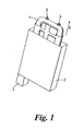
- a hollow inverted u-shaped roll bar 1 co-operates with a roll bar release mechanism 2 (whose housing alone is shown in Fig. 1 for the sake of clarity).
- the release mechanism is a spring-loaded arrangement.
- the spring-loaded arrangement could be replaced with a pyrotechnic mechanism.
- the release mechanism is activated by a release device 3 which this example is a solenoid switch. (As an alternative, a pyrotechnic actuator could be used).
- the roll bar 1, spring-loaded arrangement 2 and solenoid switch 3, operate in a known manner, i.e. when a remotely-generated trigger signal is received by the solenoid switch 3, the switch activates the release mechanism 2 and as a consequence, the roll bar 1 is deployed upwards out of the housing 2 (in the direction of arrow A).
- Conventional locking means prevent the roll bar 1 from moving any further or from being pushed back into the housing by any external force once the roll bar 1 has reached its fully-deployed position.
- the roll bar 2 is fitted with two pins 4.
- each pin 4 consists of a threaded portion 5, an integral lock nut 6 and an end portion 7 having a frusto-conical form.
- the threaded portion co-operates with a tapped hole 8 in the upper surface 9 of the roll bar1.
- Each pin 4 is located close to the shoulders 10, 11 of the roll bar.
- the threaded portion 5 and lock nut 6 are made of steel and the end portion 7 is composed of tungsten carbide and bonded to the lock nut 6 using a suitable epoxy resin adhesive. (Alternatively, the end portion 7 can be brazed to the lock-nut 6).
- Fig. 3A the roll bar arrangement of Figs. 1 and 2 is shown incorporated in a convertible vehicle 12 which includes a removable or folding roof 13 incorporating rear window 14 made of glass, a seat 15 and rear bulkhead 16. The rest of the vehicle is omitted for the sake of clarity.
- the roll-bar arrangement 1, 2, 3, 4 of Figs 1 and 2 is secured to the rear bulkhead 16 behind the seat 15.
- a vehicle motion sensor 17, of conventional design whose electrical output (not shown) is connected to the solenoid switch 3.
- An item of trim 18 is positioned over the upper surface of the roll bar, hiding the roll bar 1 from view whilst in its un-deployed, stowed position in the housing 2.
- the vehicle motion sensor 17 When the vehicle motion sensor 17 detects that rollover of the vehicle 12 is imminent, it transmits a trigger signal to the solenoid switch 3 which in turn, activates the release mechanism 2. Consequently, the roll bar 1 is rapidly deployed upwards (in the direction of arrow B). As the roll bar 1 deploys in this way, it displaces the trim item 18 and continues upwards towards the glass rear window 14 whereupon the end portion 7 of at least one of the pins 4 strikes the window causing the latter to shatter into many fragments 19. Once the roll bar 1 is deployed to its fullest extent, it locks in position just beyond the roof line as defined by the profile of the rear window 14 and clear of the head of any occupant of the seat 15, thus affording the necessary protection.
- Fig. 4 shows the roll bar arrangement of Figs. 1 and 2 incorporated in the backrest of the seat 15 rather than being attached to the rear bulkhead. Also in this example, the trim item 18 is made of a frangible material. Otherwise, the constituents of the arrangement illustrated in Fig. 4 are the same as those in Figs. 3A and 3B .
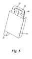
- a hollow inverted u-shaped roll bar 20 co-operates with a roll bar release mechanism 21 (whose housing alone is shown in Fig. 1 for the sake of clarity).
- the release mechanism is a spring-loaded arrangement.
- the spring-loaded arrangement could be replaced with a pyrotechnic mechanism.
- the release mechanism is activated by release device 22 which in this example is a solenoid switch. (As an alternative, a pyrotechnic actuator could be used).
- the roll bar 20, spring loaded arrangement 21 and solenoid switch 22 operate in a known manner, i.e. when a remotely-generated trigger signal is received by the solenoid switch 22; the switch activates the release mechanism 21 and as a consequence, the roll bar 20 is deployed upwards out of the housing 21 (in the direction of arrow A).
- Conventional locking means prevent the roll bar 20 from moving any further or from being pushed back into the housing by any external force once the roll bar 20 has reached its fully-deployed position.
- the delay between receiving a trigger signal at the solenoid switch 22 and deployment of the roll bar 20 is typically no more than 150ms.
- the roll bar 20 is fitted with two pyrotechnic actuators 23 to be described hereinbelow.
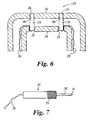
- each pyrotechnic actuator 23 is secured to an upper surface 24 of the roll bar 20 by means of a screw-threaded part 25 which co-operates with a tapped hole 26 in the upper surface 24.
- Each actuator 23 is positioned so that its upper face is substantially flush with the upper surface 24 of the roll bar 20 and is put into position by feeding it through an access hole 27 provided in a lower surface 28 of the roll bar 20.
- Electrical leads 29, connecting each actuator 23 to a control circuit are fed through the hollow part of the roll bar 20 into the housing 21.
- each pyrotechnic actuator 23 Inside each pyrotechnic actuator 23 is a combustion chamber, stored pyrotechnic material in powder form and a deployable pin 30 having an end portion 31, frusto-conical in form and made from tungsten carbide. A signal supplied via the electrical leads 29 activates an igniter inside the actuator. The time delay between ignition and deployment of the pin to its fullest extent is typically 2ms.
- Fig. 7 shows a pyrotechnic actuator 23 in its deployed configuration with the pin 30 having been ejected from its stowed position.
- Each actuator 23 deploys its pin 30 in a conventional manner, and is locked into a fixed position once it has been deployed to its fullest extent.
- Fig. 8A the roll bar arrangement of Figs. 5 and 6 is shown incorporated in a convertible vehicle 32 which includes a removable or folding roof 33 incorporating rear window 34 made of glass, a seat 35 and a rear bulkhead 36. The rest of the vehicle is omitted for the sake of clarity.
- the roll bar arrangement 21, 22, 23, 24 of Figs. 5 and 6 is secured to the rear bulkhead 36 behind the seat 35.
- a vehicle motion sensor 37 Also fitted to the vehicle is a vehicle motion sensor 37, of conventional design, whose electrical output (not shown) is connected to the solenoid switch 22.
- a delay circuit 38 is also fitted to the vehicle. This circuit is electrically connected to the motion sensor 37 and to each pyrotechnic actuator 23.
- An item of trim 39 is positioned over the upper surface of the roll bar, so hiding the roll bar 20 from view whilst in its undeployed, stowed position in the housing 21.
- the vehicle motion sensor 37 detects that rollover of the vehicle 32 is imminent it generates and transmits a trigger signal to the solenoid switch 22 and to the delay circuit 38. Consequently, the solenoid switch 22 activates the release mechanism 21 and the roll bar 20 commences to move upwards in the direction of arrow B.
- the delay circuit relays the trigger signal to the pyrotechnic actuators 23 which fire their pins 30.
- the pins 30 reach their fully deployed position, the end portion 31 of at least one of the pins 30 strikes the window 34 causing the latter to shatter into many fragments 40.
- Fig. 9 shows the roll bar arrangement of Figs. 5 and 6 incorporated in the backrest of the seat 35 rather than being attached to the rear bulkhead.
- the trim item 39 is made of frangible material.
- the constituents of the arrangement illustrated in Fig. 9 are the same as those in Figs. 8A and 8B , and they operate in the same manner.
- the roll bar 20 As the roll bar 20 is deployed upwards, it first breaks through the frangible trim item 39. Once this is cleared, the actuator pins 30 are deployed and the roll bar 20 continues upwards, whereupon the end portion 31 of at least one of the pins 30 strikes the window 34 causing it to shatter.
Landscapes
- Engineering & Computer Science (AREA)
- Mechanical Engineering (AREA)
- Body Structure For Vehicles (AREA)
Claims (37)
- Überrollbügelanordnung (1, 2, 3, 4) für ein Fahrzeug (12), wobei die Anordnung einen ausfahrbaren Überrollbügel (1) mit einem Stift (4) enthält, der von einer Oberseite des ausfahrbaren Überrollbügels (1) vorragt, um ein Heckfenster (14) des Fahrzeugs bei Ausfahren des Überrollbügels (1) zu zerbrechen.
- Überrollbügelanordnung nach Anspruch 1, wobei der Stift (4) einen Teil (5), der an der Oberseite (9) des Überrollbügels (1) befestigt ist, und ein Teil (7), das von der Oberseite des Überrollbügels vorragt, aufweist.
- Überrollbügelanordnung nach Anspruch 2, wobei der Stift (4) mittels einer Gewindeverbindung an der Oberseite des Überrollbügels befestigt ist.
- Überrollbügelanordnung nach Anspruch 2 oder 3, wobei ein vorragendes Teil (7) des Stifts eine Kegelstumpfform aufweist.
- Überrollbügelanordnung nach einem der Ansprüche 2 bis 4, wobei ein vorragendes Teil (7) des Stifts aus Wolframkarbid besteht.
- Überrollbügelanordnung nach irgendeinem vorhergehenden Anspruch, weiterhin mit einem federbelasteten Mittel (2) und einem Magnetschalter (3) zum Bewirken des Ausfahrens des Überrollbügels (1) .
- Überrollbügelanordnung nach einem der Ansprüche 1 bis 5, und weiterhin mit einem federbelasteten Mittel (2) und einer pyrotechnischen Vorrichtung (3) zum Bewirken des Ausfahrens des Überrollbügels.
- Überrollbügelanordnung nach einem der Ansprüche 1 bis 5, und weiterhin mit einem pyrotechnischen Mittel (2) zum Bewirken des Ausfahrens des Überrollbügels (1).
- Überrollbügelanordnung nach einem der Ansprüche 1 bis 8, weiterhin mit einem Sensormittel (17) zur Erfassung eines unmittelbar bevorstehenden Überschlags des Fahrzeugs und zum Erzeugen eines Steuersignals zum Ausfahren des Überrollbügels (1).
- Sitz (15) für ein Fahrzeug (12), wobei in dem Sitz eine Überrollbügelanordnung (1, 2, 3, 4) nach einem der Ansprüche 1 bis 9 eingebaut ist.
- Sitz (15) für ein Fahrzeug (12) nach Anspruch 10, weiterhin mit einem zerbrechbaren Verkleidungselement (18), das so angeordnet ist, dass es den Überrollbügel (1) bedeckt, wenn sich der Überrollbügel in einer verstauten Position befindet, und bei Ausfahren des Überrollbügels zerbrochen wird.
- Sitz (15) für ein Fahrzeug (12) nach Anspruch 10, weiterhin mit einem entfernbaren Verkleidungselement (18), das so angeordnet ist, dass es den Überrollbügel (1) bedeckt, wenn sich der Überrollbügel in einer verstauten Position befindet, und bei Ausfahren des Überrollbügels verschoben wird.
- Fahrzeug (12), das die Überrollbügelanordnung (1, 2, 3, 4) nach einem der Ansprüche 1 bis 9 enthält.
- Fahrzeug (12), das den Sitz (15) nach einem der Ansprüche 10 bis 12 enthält.
- Fahrzeug (12) nach Anspruch 13, in dem die Überrollbügelanordnung hinter einem Sitz (15) des Fahrzeugs angeordnet ist.
- Fahrzeug (12) nach Anspruch 15, weiterhin mit einem Verkleidungselement (18), das zerbrechbar ist und so angeordnet ist, dass es den Überrollbügel (1) bedeckt, wenn sich der Überrollbügel in einer verstauten Position befindet, und bei Ausfahren des Überrollbügels zerbrochen wird.
- Fahrzeug (12) nach Anspruch 15, weiterhin mit einem zerbrechbaren Verkleidungselement (18), das so angeordnet ist, dass es den Überrollbügel (1) bedeckt, wenn sich der Überrollbügel in einer verstauten Position befindet, und bei Ausfahren des Überrollbügels verschoben wird.
- Überrollbügelanordnung nach Anspruch 1, wobei der Überrollbügel (20) mit einer Öffnung (26) in seiner Oberseite (24) versehen ist und wobei der Stift (30) ausfahrbar ist und in einem pyrotechnischen Aktuator (23) enthalten ist, wobei der Aktuator so in dem Überrollbügel angeordnet ist, dass bei Ausfahren des Aktuators sich der ausfahrbare Stift durch die Öffnung über die Oberseite des Überrollbügels hinaus erstreckt.
- Überrollbügelanordnung nach Anspruch 18, wobei der pyrotechnische Aktuator (23) mittels einer Gewindeverbindung (25) an der Oberseite (24) des Überrollbügels befestigt ist.
- Überrollbügelanordnung nach Anspruch 18 oder 19, wobei ein oberes Teil (31) des ausfahrbaren Stifts (30) eine Kegelstumpfform aufweist.
- Überrollbügelanordnung nach einem der Ansprüche 18 bis 20, wobei ein oberes Teil (31) des ausfahrbaren Stifts (30) aus Wolframkarbid besteht.
- Überrollbügelanordnung nach einem der Ansprüche 18 bis 21, weiterhin mit einem federbelasteten Mittel (21) und einem Magnetschalter (22) zum Bewirken des Ausfahrens des Überrollbügels (20).
- Überrollbügelanordnung nach einem der Ansprüche 18 bis 21, weiterhin mit einem federbelasteten Mittel (21) und einer pyrotechnischen Vorrichtung (22) zum Bewirken des Ausfahrens des Überrollbügels (20).
- Überrollbügelanordnung nach einem der Ansprüche 18 bis 21, weiterhin mit einem pyrotechnischen Mittel (21) zum Bewirken des Ausfahrens des Überrollbügels.
- Überrollbügelanordnung nach einem der Ansprüche 18 bis 24, weiterhin mit einem Mittel (17) zum Erfassen eines unmittelbar bevorstehenden Überschlags des Fahrzeugs (32) und zum Erzeugen eines Steuersignals zum Ausfahren des Überrollbügels (20) und des pyrotechnischen Aktuators (23).
- Sitz (35) für ein Fahrzeug (32), wobei in dem Sitz eine Überrollbügelanordnung nach einem der Ansprüche 18 bis 25 eingebaut ist.
- Sitz (35) für ein Fahrzeug (32) nach Anspruch 26, weiterhin mit einem zerbrechbaren Verkleidungselement (18), das so angeordnet ist, dass es den Überrollbügel (20) bedeckt, wenn sich der Überrollbügel in einer verstauten Position befindet, und bei Ausfahren des Überrollbügels zerbrochen wird.
- Sitz (35) für ein Fahrzeug (32) nach Anspruch 27, weiterhin mit einem entfernbaren Verkleidungselement (18), das so angeordnet ist, dass es den Überrollbügel (20) bedeckt, wenn sich der Überrollbügel in einer verstauten Position befindet, und bei Ausfahren des Überrollbügels verschoben wird.
- Fahrzeug (32), das die Überrollbügelanordnung nach einem der Ansprüche 18 bis 25 enthält.
- Fahrzeug (32), das den Sitz (35) nach einem der Ansprüche 26 bis 28 enthält.
- Fahrzeug (32) nach Anspruch 29, in dem die Überrollbügelanordnung hinter dem Sitz (35) des Fahrzeugs angeordnet ist.
- Fahrzeug (32) nach Anspruch 31, weiterhin mit einem Verkleidungselement (39), das zerbrechbar ist und so angeordnet ist, dass es den Überrollbügel (20) bedeckt, wenn sich der Überrollbügel in einer verstauten Position befindet, und bei Ausfahren des Überrollbügels zerbrochen wird.
- Fahrzeug (32) nach Anspruch 31, weiterhin mit einem entfernbaren Verkleidungselement (39), das so angeordnet ist, dass es den Überrollbügel (20) bedeckt, wenn sich der Überrollbügel in einer verstauten Position befindet, und bei Ausfahren des Überrollbügels verschoben wird.
- Überrollbügelanordnung nach Anspruch 1, wobei der ausfahrbare Überrollbügel (1) eine umgekehrte U-Form aufweist und wobei die Vorrichtung nahe der Schulter (10) der U-Form angeordnet ist.
- Überrollbügelanordnung nach Anspruch 1, wobei der ausfahrbare Überrollbügel (1) eine umgekehrte U-Form aufweist und zwei der Vorrichtungen (4) zum Zerbrechen der Heckscheibe (14) enthält, wobei eine Vorrichtung nahe einer ersten Schulter (10) der U-Form positioniert ist und eine Vorrichtung nahe der anderen Schulter (11) der U-Form positioniert ist.
- Überrollbügelanordnung nach Anspruch 2 oder 3, wobei ein vorragendes Teil (7) des Stifts eine konische Form aufweist.
- Überrollbügelanordnung nach Anspruch 2 oder 3, wobei ein vorragendes Teil (7) des Stifts eine Kalottenform aufweist.
Applications Claiming Priority (2)
| Application Number | Priority Date | Filing Date | Title |
|---|---|---|---|
| GBGB0319981.7A GB0319981D0 (en) | 2003-08-27 | 2003-08-27 | Roll bar assembly for a vehicle |
| GB0319981 | 2003-08-27 |
Publications (2)
| Publication Number | Publication Date |
|---|---|
| EP1510412A1 EP1510412A1 (de) | 2005-03-02 |
| EP1510412B1 true EP1510412B1 (de) | 2009-11-11 |
Family
ID=28686368
Family Applications (1)
| Application Number | Title | Priority Date | Filing Date |
|---|---|---|---|
| EP04254626A Expired - Lifetime EP1510412B1 (de) | 2003-08-27 | 2004-07-31 | Überrollbügeleinheit für ein Fahrzeug |
Country Status (4)
| Country | Link |
|---|---|
| US (1) | US7407188B2 (de) |
| EP (1) | EP1510412B1 (de) |
| DE (1) | DE602004024009D1 (de) |
| GB (1) | GB0319981D0 (de) |
Cited By (1)
| Publication number | Priority date | Publication date | Assignee | Title |
|---|---|---|---|---|
| DE102012112538A1 (de) | 2012-12-18 | 2014-06-18 | Dr. Ing. H.C. F. Porsche Aktiengesellschaft | Anordnung für ein Kraftfahrzeug |
Families Citing this family (35)
| Publication number | Priority date | Publication date | Assignee | Title |
|---|---|---|---|---|
| DE20103001U1 (de) * | 2001-02-20 | 2001-06-21 | Blechformwerke Bernsbach GmbH, 08315 Bernsbach | Fahrzeugkörper für ein Pkw-Cabriolet und Baueinheit |
| DE10358774A1 (de) * | 2003-12-12 | 2005-07-14 | Brose Schließsysteme GmbH & Co.KG | Haltevorrichtung für eine Fahrzeugsicherheitseinrichtung |
| GB0423709D0 (en) * | 2004-10-26 | 2004-11-24 | Ford Global Tech Llc | Motor vehicles incorporating deployable roll bar assemblies |
| DE102004062999A1 (de) * | 2004-12-22 | 2006-07-06 | Dr.Ing.H.C. F. Porsche Ag | Kraftfahrzeug mit einem beweglichen Dach und einem ausfahrbaren Überrollschutzelement |
| US7401851B2 (en) * | 2005-12-28 | 2008-07-22 | Nissan Design America, Inc. | Stowable passenger seat with roll bar |
| US7384067B2 (en) * | 2006-01-06 | 2008-06-10 | Autoliv Asp, Inc. | Rollover protection for motor vehicles |
| DE102006006658B3 (de) * | 2006-02-14 | 2007-05-03 | Automotive Group Ise Innomotive Systems Europe Gmbh | Überrollschutzsystem für Kraftfahrzeuge mit einem aktiv aufstellbaren, einen Verschleissschutz aufweisenden Überrollbügel |
| FR2901522B1 (fr) * | 2006-05-24 | 2008-08-29 | Heuliez Sa | Dispositif de securite comprenant un arceau de securite equipe d'une protuberance et vehicule automobile equipe d'un tel dispositif |
| DE102006042257A1 (de) * | 2006-09-08 | 2008-03-27 | Dr.Ing.H.C. F. Porsche Ag | Sicherheitseinrichtung für ein Cabriolet und ein Verdeck mit einer derartigen Sicherheitseinrichtung |
| DE102007027740B4 (de) * | 2007-06-16 | 2024-02-08 | Dr. Ing. H.C. F. Porsche Aktiengesellschaft | Kraftfahrzeug mit einem beweglichen Dach und einem ausfahrbaren Überrollschutzelement |
| DE102007029097B4 (de) * | 2007-06-21 | 2009-06-18 | Ise Automotive Gmbh | Überrollschutzsystem für Kraftfahrzeuge mit zumindest einem pyrotechnisch aufstellbaren Überrollkörper |
| JP5235346B2 (ja) * | 2007-07-18 | 2013-07-10 | 日野自動車株式会社 | 車両のヘッドレスト構造 |
| DE102007061063B4 (de) | 2007-12-13 | 2018-08-16 | Metalsa Automotive Gmbh | Überrollschutzeinrichtung mit glasbrechendem Masseteil |
| DE102007061064A1 (de) | 2007-12-13 | 2009-06-25 | Ise Automotive Gmbh | Überrollschutzeinrichtung mit geschossartigem Aufbrechkörper |
| DE102007061065A1 (de) | 2007-12-13 | 2009-06-25 | Ise Automotive Gmbh | Überrollschutzeinrichtung mit Aufbrechvorrichtung |
| DE102007061014A1 (de) | 2007-12-18 | 2009-06-25 | Dr. Ing. H.C. F. Porsche Aktiengesellschaft | Kraftfahrzeug mit einer verlagerbaren Dachanordnung und einem Überrollschutzelement |
| DE102008005451B4 (de) | 2008-01-22 | 2019-05-02 | Dr. Ing. H.C. F. Porsche Aktiengesellschaft | Überrollschutzsystem für ein Kraftfahrzeug |
| IT1393409B1 (it) * | 2008-10-24 | 2012-04-20 | Maserati Spa | Dispositivo per la rottura del lunotto posteriore di un veicolo. |
| DE102009025446B4 (de) * | 2009-06-10 | 2026-01-22 | Dr. Ing. H.C. F. Porsche Aktiengesellschaft | Kraftfahrzeug mit einem verstellbaren Dach und einem ausfahrbaren Überrollschutzelement |
| DE102009034662A1 (de) | 2009-07-24 | 2011-01-27 | Dr. Ing. H.C. F. Porsche Aktiengesellschaft | Geschlossener Personenkraftwagen mit einer Überrollschutzeinrichtung |
| DE102009034641A1 (de) | 2009-07-24 | 2011-02-03 | Dr. Ing. H.C. F. Porsche Aktiengesellschaft | Offener Personenkraftwagen mit einer Überrollschutzeinrichtung |
| US8186187B2 (en) * | 2009-10-02 | 2012-05-29 | Stanton Concepts, L.L.C. | Dual custody privacy padlock |
| US11198408B2 (en) | 2009-11-12 | 2021-12-14 | Excel Industries, Inc. | Control system for a terrain working vehicle having an operator protection apparatus |
| US10493939B2 (en) | 2015-02-13 | 2019-12-03 | Excel Industries, Inc. | Lever-actuated operator protection apparatus |
| US8905434B1 (en) | 2009-11-12 | 2014-12-09 | Excel Industries, Inc. | Rollover protection apparatus |
| US9573548B2 (en) * | 2015-02-13 | 2017-02-21 | Excel Industries, Inc. | Operator protection apparatus with an over-center linkage |
| US11724658B2 (en) | 2009-11-12 | 2023-08-15 | Excel Industries, Inc. | Control system for a terrain working vehicle having an operator protection apparatus |
| US10377333B2 (en) | 2009-11-12 | 2019-08-13 | Excel Industries, Inc. | Deployable operator protection apparatus with an over-center linkage |
| NL2004482C2 (nl) * | 2010-03-31 | 2011-10-03 | Oosterhuis Beheer B V As | Ruitbrekersysteem, veiligheidssysteem en voertuig voorzien hiervan en werkwijze hiervoor. |
| DE102010036670B4 (de) * | 2010-07-28 | 2025-10-30 | Dr. Ing. H.C. F. Porsche Aktiengesellschaft | Cabriolet-Fahrzeug |
| DE102014103501A1 (de) * | 2014-03-14 | 2015-09-17 | Euwe Eugen Wexler Gmbh | Verfahren zur Herstellung eines Kunststoffbauteils mittels eines Spritzgießprozesses |
| DE102015109859A1 (de) * | 2015-06-19 | 2016-12-22 | Dr. Ing. H.C. F. Porsche Aktiengesellschaft | Überrollschutzsystem für ein Kraftfahrzeug |
| US10071701B1 (en) * | 2017-03-07 | 2018-09-11 | Ford Global Technologies, Llc | Vehicle rollover safety system |
| DE102017130590A1 (de) | 2017-12-19 | 2019-06-19 | Dr. Ing. H.C. F. Porsche Aktiengesellschaft | Kraftfahrzeug mit einer Dachanordnung |
| JP7056288B2 (ja) * | 2018-03-22 | 2022-04-19 | トヨタ自動車株式会社 | 車両の制御装置 |
Family Cites Families (13)
| Publication number | Priority date | Publication date | Assignee | Title |
|---|---|---|---|---|
| DE3410676C1 (de) * | 1984-03-23 | 1985-07-25 | Daimler-Benz Ag, 7000 Stuttgart | UEberrollschutzvorrichtung fuer einen Kraftwagen |
| DE3712940C1 (de) | 1987-04-16 | 1988-09-01 | Daimler Benz Ag | UEberrollbuegel fuer Kraftwagen |
| DE3903459A1 (de) * | 1989-02-06 | 1990-08-23 | Audi Ag | Kraftwagen in cabrio-bauweise mit einem ueberrollbuegel |
| DE3922509A1 (de) * | 1989-07-08 | 1991-01-17 | Daimler Benz Ag | Kopfstuetze fuer ruecksitze |
| DE3925515C1 (de) * | 1989-08-02 | 1991-01-31 | Bayerische Motoren Werke Ag, 8000 Muenchen, De | |
| DE3927265C3 (de) * | 1989-08-18 | 2003-03-27 | Ise Gmbh | Insassenschutzeinrichtung für Kraftfahrzeuge mit einem Überrollbügel |
| DE19650593A1 (de) * | 1996-12-06 | 1998-06-10 | Bayerische Motoren Werke Ag | Überrollschutzsystem für einen Personenkraftwagen |
| DE29807322U1 (de) * | 1998-04-22 | 1998-10-22 | Blechformwerke Bernsbach GmbH, 08315 Bernsbach | Überrollbügel |
| DE19834689A1 (de) * | 1998-07-31 | 2000-02-03 | Bayerische Motoren Werke Ag | Überrollschutz-System für ein Kraftfahrzeug, insbesondere für ein Cabriolet |
| DE19906912C1 (de) * | 1999-02-19 | 2000-04-13 | Ise Gmbh | Überroll-Schutzsystem für Kraftfahrzeuge |
| FR2791021B1 (fr) * | 1999-03-16 | 2001-05-11 | France Design | Arceau de protection pour vehicule decouvrable a toit repliable |
| US6525655B2 (en) * | 2001-06-28 | 2003-02-25 | Tien-Tsai Huang | Diaphragm-type tire pressure indicator |
| DE10151387C1 (de) * | 2001-10-18 | 2002-11-21 | Ise Gmbh | Überrollschutzsystem für Kraftfahrzeuge |
-
2003
- 2003-08-27 GB GBGB0319981.7A patent/GB0319981D0/en not_active Ceased
-
2004
- 2004-07-31 DE DE602004024009T patent/DE602004024009D1/de not_active Expired - Lifetime
- 2004-07-31 EP EP04254626A patent/EP1510412B1/de not_active Expired - Lifetime
- 2004-08-26 US US10/927,246 patent/US7407188B2/en not_active Expired - Lifetime
Cited By (1)
| Publication number | Priority date | Publication date | Assignee | Title |
|---|---|---|---|---|
| DE102012112538A1 (de) | 2012-12-18 | 2014-06-18 | Dr. Ing. H.C. F. Porsche Aktiengesellschaft | Anordnung für ein Kraftfahrzeug |
Also Published As
| Publication number | Publication date |
|---|---|
| EP1510412A1 (de) | 2005-03-02 |
| GB0319981D0 (en) | 2003-10-01 |
| US7407188B2 (en) | 2008-08-05 |
| US20050082808A1 (en) | 2005-04-21 |
| DE602004024009D1 (de) | 2009-12-24 |
Similar Documents
| Publication | Publication Date | Title |
|---|---|---|
| US7407188B2 (en) | Roll bar assembly for a vehicle | |
| EP1652736B1 (de) | Kraftfahrzeug mit ausfahrbarer Überrollschutzanordnung | |
| EP2988975B1 (de) | Obere halterung für seitenairbag | |
| US9266494B2 (en) | Fold over design for small overlap | |
| US6029993A (en) | Side airbag device, method for operation thereof and vehicle seat therewith | |
| WO2015065272A1 (en) | Curtain airbag for a vehicle and a restraining arrangement | |
| SK15142001A3 (sk) | Bezpečnostný nárazník s prvkom pohlcujúcim energiu, ovládateľným nárazovým senzorom | |
| US6299203B1 (en) | Airbag device in a vehicle and method for activating an airbag device | |
| JPH09183348A (ja) | 展開可能なカーテン抑制装置 | |
| US6991257B2 (en) | Side airbag for a vehicle | |
| US6286858B1 (en) | Energy absorbing air bag module | |
| US20040135353A1 (en) | Glove compartment airbag system | |
| US7311169B1 (en) | Door system for automotive vehicle | |
| PL194447B1 (pl) | Układ do awaryjnego otwierania drzwi pojazdu | |
| CN116075448A (zh) | 行人保护装置 | |
| WO2010027621A1 (en) | Inflator for an airbag | |
| JP2002514549A (ja) | 安全ステアリングコラム、自動車の安全システムおよび安全システムを備える自動車ならびに安全方法 | |
| US7578520B2 (en) | Airbag module | |
| US20060131862A1 (en) | Motor vehicle with a movable roof and an extensible rollover protection element | |
| GB2364674A (en) | A vehicle air-bag arrangement in which the air-bag is deployed in front of and from above the occupant | |
| US7293799B2 (en) | Gas bag module | |
| WO2001012474A1 (en) | Improvements in or relating to an air-bag arrangement | |
| JP2005022596A (ja) | 乗員保護機能付シート | |
| US20100171295A1 (en) | Driver's air bag | |
| DE102005001597B4 (de) | Sicherheitssystem |
Legal Events
| Date | Code | Title | Description |
|---|---|---|---|
| PUAI | Public reference made under article 153(3) epc to a published international application that has entered the european phase |
Free format text: ORIGINAL CODE: 0009012 |
|
| AK | Designated contracting states |
Kind code of ref document: A1 Designated state(s): AT BE BG CH CY CZ DE DK EE ES FI FR GB GR HU IE IT LI LU MC NL PL PT RO SE SI SK TR |
|
| AX | Request for extension of the european patent |
Extension state: AL HR LT LV MK |
|
| 17P | Request for examination filed |
Effective date: 20050902 |
|
| AKX | Designation fees paid |
Designated state(s): DE FR GB |
|
| RAP1 | Party data changed (applicant data changed or rights of an application transferred) |
Owner name: FORD GLOBAL TECHNOLOGIES, LLC. |
|
| 17Q | First examination report despatched |
Effective date: 20061222 |
|
| GRAP | Despatch of communication of intention to grant a patent |
Free format text: ORIGINAL CODE: EPIDOSNIGR1 |
|
| GRAS | Grant fee paid |
Free format text: ORIGINAL CODE: EPIDOSNIGR3 |
|
| GRAA | (expected) grant |
Free format text: ORIGINAL CODE: 0009210 |
|
| AK | Designated contracting states |
Kind code of ref document: B1 Designated state(s): DE FR GB |
|
| REG | Reference to a national code |
Ref country code: GB Ref legal event code: FG4D |
|
| REF | Corresponds to: |
Ref document number: 602004024009 Country of ref document: DE Date of ref document: 20091224 Kind code of ref document: P |
|
| PLBE | No opposition filed within time limit |
Free format text: ORIGINAL CODE: 0009261 |
|
| STAA | Information on the status of an ep patent application or granted ep patent |
Free format text: STATUS: NO OPPOSITION FILED WITHIN TIME LIMIT |
|
| 26N | No opposition filed |
Effective date: 20100812 |
|
| REG | Reference to a national code |
Ref country code: FR Ref legal event code: PLFP Year of fee payment: 13 |
|
| REG | Reference to a national code |
Ref country code: FR Ref legal event code: PLFP Year of fee payment: 14 |
|
| REG | Reference to a national code |
Ref country code: FR Ref legal event code: PLFP Year of fee payment: 15 |
|
| P01 | Opt-out of the competence of the unified patent court (upc) registered |
Effective date: 20230620 |
|
| PGFP | Annual fee paid to national office [announced via postgrant information from national office to epo] |
Ref country code: FR Payment date: 20230616 Year of fee payment: 20 |
|
| PGFP | Annual fee paid to national office [announced via postgrant information from national office to epo] |
Ref country code: GB Payment date: 20230614 Year of fee payment: 20 |
|
| PGFP | Annual fee paid to national office [announced via postgrant information from national office to epo] |
Ref country code: DE Payment date: 20230614 Year of fee payment: 20 |
|
| REG | Reference to a national code |
Ref country code: DE Ref legal event code: R071 Ref document number: 602004024009 Country of ref document: DE |
|
| REG | Reference to a national code |
Ref country code: GB Ref legal event code: PE20 Expiry date: 20240730 |
|
| PG25 | Lapsed in a contracting state [announced via postgrant information from national office to epo] |
Ref country code: GB Free format text: LAPSE BECAUSE OF EXPIRATION OF PROTECTION Effective date: 20240730 |
|
| PG25 | Lapsed in a contracting state [announced via postgrant information from national office to epo] |
Ref country code: GB Free format text: LAPSE BECAUSE OF EXPIRATION OF PROTECTION Effective date: 20240730 |