EP1510372A1 - Ankupplungshilfsvorrichtung - Google Patents
Ankupplungshilfsvorrichtung Download PDFInfo
- Publication number
- EP1510372A1 EP1510372A1 EP04020075A EP04020075A EP1510372A1 EP 1510372 A1 EP1510372 A1 EP 1510372A1 EP 04020075 A EP04020075 A EP 04020075A EP 04020075 A EP04020075 A EP 04020075A EP 1510372 A1 EP1510372 A1 EP 1510372A1
- Authority
- EP
- European Patent Office
- Prior art keywords
- ball
- coupling
- base body
- trailer
- auxiliary
- Prior art date
- Legal status (The legal status is an assumption and is not a legal conclusion. Google has not performed a legal analysis and makes no representation as to the accuracy of the status listed.)
- Granted
Links
Images


Classifications
-
- B—PERFORMING OPERATIONS; TRANSPORTING
- B60—VEHICLES IN GENERAL
- B60D—VEHICLE CONNECTIONS
- B60D1/00—Traction couplings; Hitches; Draw-gear; Towing devices
- B60D1/58—Auxiliary devices
- B60D1/60—Covers, caps or guards, e.g. comprising anti-theft devices
- B60D1/605—Protection caps
-
- B—PERFORMING OPERATIONS; TRANSPORTING
- B60—VEHICLES IN GENERAL
- B60D—VEHICLE CONNECTIONS
- B60D1/00—Traction couplings; Hitches; Draw-gear; Towing devices
- B60D1/01—Traction couplings or hitches characterised by their type
- B60D1/06—Ball-and-socket hitches
-
- B—PERFORMING OPERATIONS; TRANSPORTING
- B60—VEHICLES IN GENERAL
- B60D—VEHICLE CONNECTIONS
- B60D1/00—Traction couplings; Hitches; Draw-gear; Towing devices
- B60D1/24—Traction couplings; Hitches; Draw-gear; Towing devices characterised by arrangements for particular functions
- B60D1/36—Traction couplings; Hitches; Draw-gear; Towing devices characterised by arrangements for particular functions for facilitating connection, e.g. hitch catchers
-
- B—PERFORMING OPERATIONS; TRANSPORTING
- B60—VEHICLES IN GENERAL
- B60D—VEHICLE CONNECTIONS
- B60D1/00—Traction couplings; Hitches; Draw-gear; Towing devices
- B60D1/58—Auxiliary devices
- B60D1/60—Covers, caps or guards, e.g. comprising anti-theft devices
Definitions
- the present invention relates to a coupling auxiliary device for trailers, in particular caravan, wherein the Ankupplungscousvorraum at least one Display and positioning device for displaying the position of a trailer hitch of the trailer relative to a towing vehicle.
- Rammschutze or baffles To damage the towing vehicle or the trailer at a to prevent accidental collision during a coupling process are used so-called Rammschutze or baffles. These exist usually made of an elastic material and are on or before the Ball socket a coupling claw of the trailer arranged. Examples of this are in DE 33 41 705 A1, DE 39 15 944 A1 or DE 200 14 237 U1 disclosed. A disadvantage of these devices, however, is that even these lack Orientation aids an accidental collision between the towing vehicle and the trailer can not prevent it from being damaged the towing vehicle or trailer and in particular the Hitch adapter comes.
- a coupling auxiliary device of the type mentioned above on the one hand the distance and the relative position between tractor and trailer indicates and on the other hand an accidental collision damage to the trailer and / or on the Towing vehicle, especially the Ankupplungssvortechnisch itself as far as possible prevented.
- a coupling auxiliary device has at least one Display and positioning device for displaying the position of a Trailer hitch of the trailer relative to a towing vehicle and is from a base body with a ball for engagement and for releasable attachment with a ball socket of a coupling claw of the trailer and a the Body at least partially surrounding in the direction of the towing vehicle Rammschutz of compressible material, wherein the display and Positioning device is arranged in the main body or the Rammschutz.
- the display and Positioning device is arranged in the main body or the Rammschutz.
- the driver of the Towing vehicle indicated that the coupling device of the towing vehicle now rests on the coupling auxiliary device of the trailer. This is ensures that, on the one hand, the relative position between the towing vehicle and the trailer is displayed and on the other hand in an unwanted Collision between the trailer and the towing vehicle Damage reliably prevented at these.
- the clutch claw is also in the range the ball socket with attached coupling auxiliary device against dirt and dust protected.
- the coupling auxiliary device can also for Accident prevention can be used as the ramming protection prevents persons can injure yourself at the coupling claw.
- the Rammschutz and / or the body made of plastic or rubber. It can the ramming protection and the body are integrally formed. It is also possible that the crash protection is designed detachable from the body.
- the ram protection consists of a Gas or liquid filled volume. This can be for example a pneumatic tire or - be hose.
- the enclose Rammschutz and / or surrounding the body side wall of the ball in Direction of the tractor at least partially.
- they can Ball in the direction of the tractor at least partially semicircular enclose.
- the ramming protection and / or a the Body surrounding sidewall formed over the ball protruding are.
- the display and a rod positioning device with at least one indicator pennant are variable.
- the ball of the Anchorage auxiliary device a locking mechanism for locking the Ball with a ball socket of the coupling claw of the trailer.
- the coupling auxiliary device also as theft protection can be used as a coupling of the trailer to a towing vehicle with attached coupling auxiliary device is not possible.
- Locking mechanism can advantageously from a two-part built-up ball with an upper and a lower half ball as well at least one locking pin, which is arranged between the ball halves, exist, with the upper half of the ball compared to the lower half of the ball is formed movable and upon movement of the upper half of the ball on the Lower half of the ball locking pin outward over the circumference of the ball is pushed and against the inner circumference of the ball socket the Clutch claw presses.
- the Locking mechanism with a in the opening in which the hexagon screw guided, retractable lock be lockable.
- FIG. 1 shows a schematic and partially sectioned illustration of a coupling auxiliary device 10 according to a first embodiment.
- the coupling aid 10 has a display and positioning device 12 for Display of the position of a trailer hitch of the trailer relative to a towing vehicle on. It can be seen that the coupling auxiliary device 10 from a Base body 14 with a bottom element 16 is. On the bottom element 16 is a holding element 40 for supporting and holding a ball 18 is formed. The Ball 18 serves for engagement and releasable attachment with a ball socket 22 of a coupling claw 20 of the trailer. Furthermore, one recognizes that the coupling auxiliary device 10 a the base body 16 in the direction of Towing vehicle surrounding ram guard 24 made of compressible material. The ram guard 24 closes in the illustrated embodiment to a side wall 30 of the base body 14 at.
- the display and positioning device 12 is in the illustrated embodiment from a rod 26 (shown shortened in the figures) with one arranged at one end of the rod 26 display pennant 28. Also other optical or acoustic signal are conceivable.
- the rod 26 is here arranged in the base body 14. But it is also possible that the display and positioning device 12 is connected to the ram guard 24. At a Touching the Rammschutzes 24 is a compression of the Rammschutzes 24 and thereby a movement of the display and positioning device 12. This movement indicates to the driver of the towing vehicle that the coupling device of the towing vehicle now at the Ankupplungssvortechnisch 10 of the trailer is present.
- the ram protection 24 and / or the base 14 usually consist of Plastic or rubber.
- the Rammtik 24 and the main body 14th be formed integrally.
- the Rammstoff 24 removable trained. But it is also possible that the Rammtik 24 consists of a filled with gas or liquid volume (not shown).
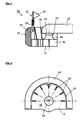
- Figure 2 shows a plan view of the coupling auxiliary device 10 according to the in Figure 1 illustrated embodiment. It can be seen that both the basic body 14 as well as the Rammschutz 24 semicircular or U-shaped are formed. In this case, the Rammschutz 24 surrounding the main body 14 almost completely and is arranged along the side wall 30 of the base body 14.
- Figure 3 shows a side view of the coupling auxiliary device 10 according to the in The embodiment illustrated in Figures 1 and 2. This is especially the configuration of the base body 14 with the radially inwardly arranged Strive 38 clearly. Furthermore, it can be seen that the ball 18 in her after Outside area is fully formed and on the holding element 40th seated.
- the ball 18 and the holding member 40 may be integral with be formed of the base body 14. But it is also possible that the ball 18 and / or the holding member 40 glued or screwed to the base body 14 are.
- FIG. 4 shows a sectional view of a coupling auxiliary device 10 according to FIG a second embodiment.
- the illustrated coupling auxiliary device 10 has a base body 14, which in the Floor element 16 has an opening 48, wherein within the opening 48, the passes through the bottom member 16 and the holding member 40 therethrough, a Allen screw 42 is guided and rotatable.
- the ball 18 facing end of the hexagon socket screw 42 engages in a self-locking nut 44, which within an opening 50 in the ball 18th is arranged.
- the opening 50 opposite recess 72 of the ball 18, a sleeve 46 is arranged, which is the leadership of the hexagon socket screw 42 within the ball 18 is used.
- FIG. 5 shows a sectional representation of a third embodiment of the coupling auxiliary device 10.
- an additional Sleeve 52 which, via the hexagon socket screw 42 on the bottom element 16 is attached.
- the sleeve 52 protrudes from the bottom element 16 out and has at the protruding portion an opening 74 for implementation a safety rope 54.
- the safety cable 54 prevents this unwanted removal of the coupling auxiliary device 10 from the trailer.
- FIG. 6 shows a sectional view of a fourth embodiment of the coupling auxiliary device 10.
- the locking mechanism 32 consists of a two-piece ball 18 with an upper and a lower half ball 34, 36 and four expansion pins 64, which are arranged between the ball halves 34, 36 are.
- the upper ball half 34 is opposite the lower ball half 36th designed to be movable.
- the movement of the upper ball half 34 with respect to lower ball half 36 is arranged by means of in the below the ball 18 Opening 48 of the body guided and rotatable hex screw or hexagon socket screw 42 performed.
- the hexagon socket screw 42 engages with her ball 18 facing the end in a clamping bolt 60, wherein the clamping bolt 60 in an opening 70 of the upper Ball half 36 comes to rest. It can be seen that the clamping bolt 60 against a cone 66 pushes, in turn, with its circumference against the expansion pins 64th suppressed. Now is the upper ball half 34 and the clamping bolt 60 pressed in the direction of the bottom element 16 of the base body 14, so the expansion pins 64 are pushed outwards over the circumference of the ball 18 and press against the inner circumference of the ball socket 22.
- a plate spring 62 is also arranged, on the one hand for easy release of the lock and on the other a back pressure against too much compressive stress of the upper Ball half 34 and the clamping bolt 60 effect.
- the designated A Illustration of the locking mechanism 32 shows the locking mechanism 32 in non-activated state, d. H. with expanding pins 64, the are still within the spherical circumference of the ball 18.
- the marked B Illustration shows the locking mechanism 32 with extended Spreader pins 64.
- the locking mechanism 32 is closable.
- an additional Lock receptacle 56 introduced in the opening 48 of the bottom element 16 .
- the connection of the lock receptacle 56 with the bottom element 16 takes place via the hexagon socket screw 42.
- a lock 58 can be used in the lock receptacle 56 then a lock 58 can be used.
- the locking mechanism 32 in turn from a two-piece ball 18 with an upper and a lower ball half 34, 36. Between the ball halves 34, however, an elastomeric material 68 is arranged.
- the upper ball half 34 is formed in turn movable relative to the lower ball half 36, so that with a movement of the upper ball half 34 on the lower ball half 36 the elastomeric material 68 is pushed outwardly over the circumference of the ball 18 is pressed against the inner periphery of the ball socket 22. Also by this is a reliable locking of the ball 18 with the ball socket 22 of the coupling jaw 20 possible.
- this locking mechanism 32 is by means of Lock 58 lockable.
- the designated A representation of the locking mechanism 32 shows the locking mechanism 32 in unactivated State, d. H. with an elastic material 68, which is still inside the ball circumference of the ball 18 is located.
- the representation marked with B shows the locking mechanism 32 with ejected elastic material 68th
Landscapes
- Engineering & Computer Science (AREA)
- Transportation (AREA)
- Mechanical Engineering (AREA)
- Clamps And Clips (AREA)
- Lighting Device Outwards From Vehicle And Optical Signal (AREA)
Abstract
Description
- Figur 1
- eine schematische und teilweise geschnittene Darstellung einer erfindungsgemäßen Ankupplungshilfsvorrichtung gemäß einer ersten Ausführungsform;
- Figur 2
- eine Aufsicht auf die erfindungsgemäßen Ankupplungshilfsvorrichtung gemäß Figur 1;
- Figur 3
- eine Seitenansicht der erfindungsgemäßen Ankupplungshilfsvorrichtung gemäß Figur 1;
- Figur 4
- eine Schnittdarstellung der erfindungsgemäßen Ankupplungshilfsvorrichtung gemäß einer zweiten Ausführungsform;
- Figur 5
- eine Schnittdarstellung einer dritten Ausführungsform der erfindungsgemäßen Ankuppelungshilfsvorrichtung;
- Figur 6
- eine Schnittdarstellung einer vierten Ausführungsform der erfindungsgemäßen Ankuppelungshilfsvorrichtung; und
- Figur 7
- eine Schnittdarstellung einer fünften Ausführungsform der erfindungsgemäßen Ankuppelungshilfsvorrichtung
Claims (17)
- Ankupplungshilfsvorrichtung für Anhänger, insbesondere Wohnwagen, wobei die Ankupplungshilfsvorrichtung (10) mindestens eine Anzeige- und Positioniervorrichtung (12) zur Anzeige der Position einer Anhängerkupplung des Anhängers relativ zu einem Zugfahrzeug aufweist,
dadurch gekennzeichnet, dass die Ankupplungshilfsvorrichtung (10) aus einem Grundkörper (14) mit einer Kugel (18) zum Eingriff und zur lösbaren Befestigung mit einer Kugelpfanne (22) einer Kupplungsklaue (20) des Anhängers und einen den Grundkörper (16) zumindest teilweise in Richtung des Zugfahrzeugs umgebenden Rammschutz (24) aus komprimierbarem Material besteht, wobei die Anzeige- und Positioniervorrichtung (12) in dem Grundkörper (14) oder dem Rammschutz (24) angeordnet ist. - Ankupplungshilfsvorrichtung nach Anspruch 1,
dadurch gekennzeichnet, dass der Rammschutz (24) und/oder der Grundkörper (14) aus Kunststoff oder Gummi bestehen. - Ankupplungshilfsvorrichtung nach Anspruch 1 oder 2,
dadurch gekennzeichnet, dass der Rammschutz (24) und der Grundkörper (14) einstückig ausgebildet sind. - Ankupplungshilfsvorrichtung nach Anspruch 1 oder 2,
dadurch gekennzeichnet, dass der Rammschutz (24) vom Grundkörper (14) abnehmbar ausgebildet ist. - Ankupplungshilfsvorrichtung nach Anspruch 1,
dadurch gekennzeichnet, dass der Rammschutz (24) aus einem mit Gas oder Flüssigkeit gefüllten Volumen besteht. - Ankupplungshilfsvorrichtung nach Anspruch 5,
dadurch gekennzeichnet, dass das Volumen aus einem Luftreifen oder -schlauch besteht. - Ankupplungshilfsvorrichtung nach einem der vorhergehenden Ansprüche,
dadurch gekennzeichnet, dass der Rammschutz (24) und/oder eine den Grundkörper (14) umgebende Seitenwand (30) die Kugel (18) in Richtung des Zugfahrzeugs zumindest teilweise umschließen. - Ankupplungshilfsvorrichtung nach Anspruch 7,
dadurch gekennzeichnet, dass der Rammschutz (24) und/oder eine den Grundkörper (14) umgebende Seitenwand (30) die Kugel (18) in Richtung des Zugfahrzeugs zumindest teilweise halbkreisförmig umschließen. - Ankupplungshilfsvorrichtung nach Anspruch 7 oder 8,
dadurch gekennzeichnet, dass der Rammschutz (24) und/oder eine den Grundkörper (14) umgebende Seitenwand (30) über die Kugel (18) hinausragend ausgebildet sind. - Ankupplungshilfsvorrichtung nach einem der vorhergehenden Ansprüche,
dadurch gekennzeichnet, dass die Anzeige- und Positioniervorrichtung (12) aus einer Stange (26) mit mindestens einem Anzeigewimpel (28) und/oder anderen optischen und/oder akustischen Signalgebern besteht. - Ankupplungshilfsvorrichtung nach einem der vorhergehenden Ansprüche,
dadurch gekennzeichnet, dass die Kugel (18) mit dem Grundkörper (14) lösbar verbunden ist. - Ankupplungshilfsvorrichtung nach einem der vorhergehenden Ansprüche,
dadurch gekennzeichnet, dass die Kugel (18) einen Verriegelungsmechanismus (32) zur Verriegelung der Kugel (18) mit der Kugelpfanne (22) der Kupplungsklaue (20) des Anhängers aufweist. - Ankupplungshilfsvorrichtung nach Anspruch 12,
dadurch gekennzeichnet, dass der Verriegelungsmechanismus (32) aus einer zweiteilig aufgebauten Kugel (18) mit einer oberen und einer unteren Kugelhälfte (34, 36) sowie mindestens einem Spreizstift (64), der zwischen den Kugelhälften (34, 36) angeordnet ist, besteht, wobei die obere Kugelhälfte (34) gegenüber der unteren Kugelhälfte (36) bewegbar ausgebildet ist und bei einer Bewegung der oberen Kugelhälfte (34) auf die untere Kugelhälfte (36) der Spreizstift (64) nach außen über den Umfang der Kugel (18) geschoben wird und gegen den inneren Umfang der Kugelpfanne (22) drückt. - Ankupplungshilfsvorrichtung nach Anspruch 12,
dadurch gekennzeichnet, dass der Verriegelungsmechanismus (32) aus einer zweiteilig aufgebauten Kugel (18) mit einer oberen und einer unteren Kugelhälfte (34, 36) besteht, wobei zwischen den Kugelhälften (34, 36) ein elastomeres Material (68) angeordnet ist und die obere Kugelhälfte (34) gegenüber der unteren Kugelhälfte (36) bewegbar ausgebildet ist, so dass bei einer Bewegung der oberen Kugelhälfte (34) auf die untere Kugelhälfte (36) das elastomere Material (68) nach außen über den Umfang der Kugel (18) geschoben wird und gegen den inneren Umfang der Kugelpfanne (22) drückt. - Ankupplungshilfsvorrichtung nach Anspruch 13 oder 14,
dadurch gekennzeichnet, dass die Bewegung der oberen Kugelhälfte (34) gegenüber der unteren Kugelhälfte (36) mittels einer in einer unterhalb der Kugel (18) angeordneten Öffnung (48) des Grundkörpers (14) geführten und drehbaren Innensechskantschraube (42) erfolgt, wobei die Innensechskantschraube (42) mit ihrem der Kugel (18) zugewandten Ende in einen Spannbolzen (60) greift und der Spannbolzen (60) in einer Öffnung (70) der oberen Kugelhälfte (36) angeordnet ist. - Ankupplungshilfsvorrichtung nach einem der Ansprüche 12 bis 15,
dadurch gekennzeichnet, dass der Verriegelungsmechanismus (32) verschließbar ist. - Ankupplungshilfsvorrichtung nach Anspruch 15 oder 16,
dadurch gekennzeichnet, dass der Verriegelungsmechanismus (32) mit einem in die Öffnung (48) des Grundkörpers (14) einschiebbaren Schloss (58) verschließbar ist.
Applications Claiming Priority (2)
| Application Number | Priority Date | Filing Date | Title |
|---|---|---|---|
| DE20313442U | 2003-08-29 | ||
| DE20313442U DE20313442U1 (de) | 2003-08-29 | 2003-08-29 | Ankupplungshilfsvorrichtung |
Publications (2)
| Publication Number | Publication Date |
|---|---|
| EP1510372A1 true EP1510372A1 (de) | 2005-03-02 |
| EP1510372B1 EP1510372B1 (de) | 2010-02-24 |
Family
ID=29414605
Family Applications (1)
| Application Number | Title | Priority Date | Filing Date |
|---|---|---|---|
| EP20040020075 Expired - Lifetime EP1510372B1 (de) | 2003-08-29 | 2004-08-24 | Ankupplungshilfsvorrichtung |
Country Status (2)
| Country | Link |
|---|---|
| EP (1) | EP1510372B1 (de) |
| DE (2) | DE20313442U1 (de) |
Cited By (4)
| Publication number | Priority date | Publication date | Assignee | Title |
|---|---|---|---|---|
| CN105774442A (zh) * | 2016-04-01 | 2016-07-20 | 浦江大口贸易有限公司 | 一种用于活动缝隙的覆盖结构 |
| CN105774437A (zh) * | 2016-04-01 | 2016-07-20 | 杨金燕 | 一种活动缝隙的新型覆盖装置 |
| CN105835639A (zh) * | 2016-04-01 | 2016-08-10 | 厦门市得么文具有限公司 | 一种用于活动缝隙的安全覆盖装置 |
| CN105966178A (zh) * | 2016-04-01 | 2016-09-28 | 厦门市得么文具有限公司 | 一种活动缝隙用的覆盖装置 |
Citations (13)
| Publication number | Priority date | Publication date | Assignee | Title |
|---|---|---|---|---|
| US3765703A (en) * | 1972-02-14 | 1973-10-16 | F Voelkerding | Trailer hitch guiding device |
| US4012056A (en) * | 1975-12-29 | 1977-03-15 | Christensen Justin D | Visual guide device for hitching vehicles |
| US4201400A (en) * | 1978-07-14 | 1980-05-06 | J. & A. Atlas Nominees Pty. Ltd | Towing device |
| DE3341705A1 (de) | 1983-11-18 | 1985-05-30 | Eduard 7140 Ludwigsburg Heinrich | Kupplungskorrosionsschutz mit auf stoss kontaktierndem optischen bzw. akustischem signalgeber |
| US4961590A (en) * | 1989-07-14 | 1990-10-09 | Duke Davenport | Trailer hitching apparatus |
| DE3915944A1 (de) | 1989-05-02 | 1990-11-08 | Holger Jensen | Zugkugelkupplung |
| US5169168A (en) * | 1990-06-21 | 1992-12-08 | Harwal Machine, Inc. | Ball hitch assembly |
| US5725232A (en) * | 1996-02-27 | 1998-03-10 | Fleming; Thomas R. | Trailer hitch guide |
| US5871222A (en) * | 1997-04-22 | 1999-02-16 | Webb; Micheal L. | Detachable ball hitch apparatus and methods |
| DE29818749U1 (de) | 1998-10-21 | 1999-04-08 | Instenberg, Jürgen, 88521 Ertingen | Zeigervorrichtung für eine Anhängerkupplung |
| DE20013337U1 (de) | 2000-08-02 | 2000-09-28 | Nachtmann, Wolfgang, 82436 Eglfing | Ankupplungshilfsvorrichtung |
| DE20014237U1 (de) | 2000-08-17 | 2000-12-14 | Lich, Willi, 64665 Alsbach-Hähnlein | Informationssystem für Autobahnzufahrten |
| DE10015335A1 (de) * | 2000-03-28 | 2001-10-04 | Volkswagen Ag | Abnehmbare Anhängevorrichtung |
Family Cites Families (13)
| Publication number | Priority date | Publication date | Assignee | Title |
|---|---|---|---|---|
| US3418628A (en) | 1965-08-23 | 1968-12-24 | Fenner George Donaldson | Alignment device for trailer |
| DE8323601U1 (de) | 1983-08-17 | 1984-02-23 | Beck, Helmut, 3207 Harsum | Warnvorrichtung |
| US4988116A (en) | 1989-04-10 | 1991-01-29 | Evertsen Gary L | Trailer hitching aid |
| US5035441A (en) | 1989-04-27 | 1991-07-30 | Spectra Technologies Inc. | Trailer hitch alignment device |
| GB2260303A (en) | 1991-09-26 | 1993-04-14 | John Patrick Buckley | Mounting |
| US5681053A (en) | 1994-05-24 | 1997-10-28 | Alpine Solutions Incorporated | Protective encasement for trailer couplers |
| DE9420675U1 (de) | 1994-12-24 | 1996-04-25 | Jensen, Holger, 24983 Handewitt | Kugelpfannenkupplung |
| US5651559A (en) | 1995-06-12 | 1997-07-29 | Liland; David K. | Protective guard for a trailer hitch housing |
| US6042136A (en) | 1998-06-22 | 2000-03-28 | Heinecke; Wayne S. | Trailer hitch guide system |
| US6139041A (en) | 1999-04-15 | 2000-10-31 | Murphy; Joseph G. | Trailer hitching alignment aid |
| DE20014537U1 (de) | 2000-08-23 | 2000-11-23 | Knott GmbH, 83125 Eggstätt | Rammschutzvorrichtung für Zugkupplungen von Kraftfahrzeug-Anhängerdeichseln |
| US6585281B1 (en) | 2002-01-30 | 2003-07-01 | Aric R. Voorting | Vehicle alignment system |
| DE20215368U1 (de) | 2002-10-07 | 2003-01-09 | Reich KG, Regel- und Sicherheitstechnik, 35713 Eschenburg | Ankuppelvorrichtung für Anhänger |
-
2003
- 2003-08-29 DE DE20313442U patent/DE20313442U1/de not_active Expired - Lifetime
-
2004
- 2004-08-24 EP EP20040020075 patent/EP1510372B1/de not_active Expired - Lifetime
- 2004-08-24 DE DE200450010798 patent/DE502004010798D1/de not_active Expired - Lifetime
Patent Citations (13)
| Publication number | Priority date | Publication date | Assignee | Title |
|---|---|---|---|---|
| US3765703A (en) * | 1972-02-14 | 1973-10-16 | F Voelkerding | Trailer hitch guiding device |
| US4012056A (en) * | 1975-12-29 | 1977-03-15 | Christensen Justin D | Visual guide device for hitching vehicles |
| US4201400A (en) * | 1978-07-14 | 1980-05-06 | J. & A. Atlas Nominees Pty. Ltd | Towing device |
| DE3341705A1 (de) | 1983-11-18 | 1985-05-30 | Eduard 7140 Ludwigsburg Heinrich | Kupplungskorrosionsschutz mit auf stoss kontaktierndem optischen bzw. akustischem signalgeber |
| DE3915944A1 (de) | 1989-05-02 | 1990-11-08 | Holger Jensen | Zugkugelkupplung |
| US4961590A (en) * | 1989-07-14 | 1990-10-09 | Duke Davenport | Trailer hitching apparatus |
| US5169168A (en) * | 1990-06-21 | 1992-12-08 | Harwal Machine, Inc. | Ball hitch assembly |
| US5725232A (en) * | 1996-02-27 | 1998-03-10 | Fleming; Thomas R. | Trailer hitch guide |
| US5871222A (en) * | 1997-04-22 | 1999-02-16 | Webb; Micheal L. | Detachable ball hitch apparatus and methods |
| DE29818749U1 (de) | 1998-10-21 | 1999-04-08 | Instenberg, Jürgen, 88521 Ertingen | Zeigervorrichtung für eine Anhängerkupplung |
| DE10015335A1 (de) * | 2000-03-28 | 2001-10-04 | Volkswagen Ag | Abnehmbare Anhängevorrichtung |
| DE20013337U1 (de) | 2000-08-02 | 2000-09-28 | Nachtmann, Wolfgang, 82436 Eglfing | Ankupplungshilfsvorrichtung |
| DE20014237U1 (de) | 2000-08-17 | 2000-12-14 | Lich, Willi, 64665 Alsbach-Hähnlein | Informationssystem für Autobahnzufahrten |
Cited By (5)
| Publication number | Priority date | Publication date | Assignee | Title |
|---|---|---|---|---|
| CN105774442A (zh) * | 2016-04-01 | 2016-07-20 | 浦江大口贸易有限公司 | 一种用于活动缝隙的覆盖结构 |
| CN105774437A (zh) * | 2016-04-01 | 2016-07-20 | 杨金燕 | 一种活动缝隙的新型覆盖装置 |
| CN105835639A (zh) * | 2016-04-01 | 2016-08-10 | 厦门市得么文具有限公司 | 一种用于活动缝隙的安全覆盖装置 |
| CN105966178A (zh) * | 2016-04-01 | 2016-09-28 | 厦门市得么文具有限公司 | 一种活动缝隙用的覆盖装置 |
| CN105966178B (zh) * | 2016-04-01 | 2018-05-25 | 安溪县都源达包装材料有限公司 | 一种活动缝隙用的覆盖装置 |
Also Published As
| Publication number | Publication date |
|---|---|
| EP1510372B1 (de) | 2010-02-24 |
| DE502004010798D1 (de) | 2010-04-08 |
| DE20313442U1 (de) | 2003-10-30 |
Similar Documents
| Publication | Publication Date | Title |
|---|---|---|
| DE69705591T2 (de) | Elektronisches Steuergerät und Sicherheitsvorrichtung für die Verbindung zwischen einem Schlepper und einem Anhänger | |
| DE102021214714A1 (de) | Losbrechabschlepphaken | |
| DE102010009986A1 (de) | Anhängekupplung mit einem Kraftsensor | |
| DE202004000387U1 (de) | Steckverbindungseinrichtung | |
| DE102010024572A1 (de) | Aufpralldämpfungsstruktur mit Crashboxen | |
| US5356166A (en) | Arrestably lockable telescoping tow-bar assembly | |
| EP1510372B1 (de) | Ankupplungshilfsvorrichtung | |
| EP3390119B1 (de) | Kupplungsvorrichtung mit aneinander festlegbaren ausrichtbauteilen | |
| DE69627370T2 (de) | Anzeigemittel in einem bremszylinder für eine fahrzeugbremse | |
| DE2219097A1 (de) | Druckanzeiger für Luftreifen | |
| EP1236590A1 (de) | Anhängerkupplung | |
| DE10015335B4 (de) | Abnehmbare Anhängevorrichtung | |
| DE102019216208A1 (de) | Fahrzeug mit einer Abschleppvorrichtung | |
| DE102013007478A1 (de) | Notbremsvorrichtung für ein Fahrzeug | |
| DE3731264C1 (en) | Coupling device for coupling a trailer to a towing vehicle | |
| DE19518633A1 (de) | Rangierhilfe für ein Fahrzeug | |
| DE3144986A1 (de) | Vorrichtung zum messen der stuetzlast eines einachsigen anhaengers | |
| DE102024202911B3 (de) | Befestigungssystem zur Aufnahme einer abnehmbaren Anhängerkupplungsstange | |
| DE20215368U1 (de) | Ankuppelvorrichtung für Anhänger | |
| DE3524238A1 (de) | Messvorrichtung zum ermitteln der deichsellast bei wohnwagen, bootsanhaengern od. dgl. | |
| DE2812750A1 (de) | Bergungsfahrzeug mit bergevorrichtung zum abschleppen von strassenfahrzeugen | |
| DE1152893B (de) | Anhaengervorrichtung an Personenkraftwagen | |
| DE3530565A1 (de) | Lagerung des kupplungskoerpers einer anhaengerkupplung in der traverse | |
| DE1698171B1 (de) | Vorrichtung zur Messung der auf ein Zugfahrzeug ausgeuebten Deichsellast | |
| DE2425936C3 (de) | Abschleppstange |
Legal Events
| Date | Code | Title | Description |
|---|---|---|---|
| PUAI | Public reference made under article 153(3) epc to a published international application that has entered the european phase |
Free format text: ORIGINAL CODE: 0009012 |
|
| AK | Designated contracting states |
Kind code of ref document: A1 Designated state(s): AT BE BG CH CY CZ DE DK EE ES FI FR GB GR HU IE IT LI LU MC NL PL PT RO SE SI SK TR |
|
| AX | Request for extension of the european patent |
Extension state: AL HR LT LV MK |
|
| 17P | Request for examination filed |
Effective date: 20050624 |
|
| AKX | Designation fees paid |
Designated state(s): DE FR GB NL |
|
| 17Q | First examination report despatched |
Effective date: 20060622 |
|
| 17Q | First examination report despatched |
Effective date: 20060622 |
|
| GRAP | Despatch of communication of intention to grant a patent |
Free format text: ORIGINAL CODE: EPIDOSNIGR1 |
|
| GRAS | Grant fee paid |
Free format text: ORIGINAL CODE: EPIDOSNIGR3 |
|
| GRAA | (expected) grant |
Free format text: ORIGINAL CODE: 0009210 |
|
| AK | Designated contracting states |
Kind code of ref document: B1 Designated state(s): DE FR GB NL |
|
| REG | Reference to a national code |
Ref country code: GB Ref legal event code: FG4D Free format text: NOT ENGLISH |
|
| REF | Corresponds to: |
Ref document number: 502004010798 Country of ref document: DE Date of ref document: 20100408 Kind code of ref document: P |
|
| REG | Reference to a national code |
Ref country code: NL Ref legal event code: T3 |
|
| PGFP | Annual fee paid to national office [announced via postgrant information from national office to epo] |
Ref country code: NL Payment date: 20100830 Year of fee payment: 7 |
|
| PGFP | Annual fee paid to national office [announced via postgrant information from national office to epo] |
Ref country code: GB Payment date: 20100831 Year of fee payment: 7 |
|
| PLBE | No opposition filed within time limit |
Free format text: ORIGINAL CODE: 0009261 |
|
| STAA | Information on the status of an ep patent application or granted ep patent |
Free format text: STATUS: NO OPPOSITION FILED WITHIN TIME LIMIT |
|
| 26N | No opposition filed |
Effective date: 20101125 |
|
| REG | Reference to a national code |
Ref country code: FR Ref legal event code: ST Effective date: 20110502 |
|
| PG25 | Lapsed in a contracting state [announced via postgrant information from national office to epo] |
Ref country code: FR Free format text: LAPSE BECAUSE OF NON-PAYMENT OF DUE FEES Effective date: 20100831 |
|
| PGFP | Annual fee paid to national office [announced via postgrant information from national office to epo] |
Ref country code: DE Payment date: 20110831 Year of fee payment: 8 |
|
| REG | Reference to a national code |
Ref country code: NL Ref legal event code: V1 Effective date: 20120301 |
|
| GBPC | Gb: european patent ceased through non-payment of renewal fee |
Effective date: 20110824 |
|
| PG25 | Lapsed in a contracting state [announced via postgrant information from national office to epo] |
Ref country code: NL Free format text: LAPSE BECAUSE OF NON-PAYMENT OF DUE FEES Effective date: 20120301 |
|
| PG25 | Lapsed in a contracting state [announced via postgrant information from national office to epo] |
Ref country code: GB Free format text: LAPSE BECAUSE OF NON-PAYMENT OF DUE FEES Effective date: 20110824 |
|
| PG25 | Lapsed in a contracting state [announced via postgrant information from national office to epo] |
Ref country code: DE Free format text: LAPSE BECAUSE OF NON-PAYMENT OF DUE FEES Effective date: 20130301 |
|
| REG | Reference to a national code |
Ref country code: DE Ref legal event code: R119 Ref document number: 502004010798 Country of ref document: DE Effective date: 20130301 |