EP1510281B2 - Reibrührschweissverfahren mit einem exothermisch reagierendem Dichtmittel und eine Reibrührschweissverbindung mit einem exothermisch reagiertem Dichtmittel - Google Patents
Reibrührschweissverfahren mit einem exothermisch reagierendem Dichtmittel und eine Reibrührschweissverbindung mit einem exothermisch reagiertem Dichtmittel Download PDFInfo
- Publication number
- EP1510281B2 EP1510281B2 EP03027702A EP03027702A EP1510281B2 EP 1510281 B2 EP1510281 B2 EP 1510281B2 EP 03027702 A EP03027702 A EP 03027702A EP 03027702 A EP03027702 A EP 03027702A EP 1510281 B2 EP1510281 B2 EP 1510281B2
- Authority
- EP
- European Patent Office
- Prior art keywords
- sealant
- interface
- joint
- faying surfaces
- friction stir
- Prior art date
- Legal status (The legal status is an assumption and is not a legal conclusion. Google has not performed a legal analysis and makes no representation as to the accuracy of the status listed.)
- Expired - Lifetime
Links
- 239000000565 sealant Substances 0.000 title claims description 150
- 238000003756 stirring Methods 0.000 title claims description 38
- 238000000034 method Methods 0.000 title claims description 30
- 238000003466 welding Methods 0.000 title claims description 30
- 239000000463 material Substances 0.000 claims description 47
- 238000006243 chemical reaction Methods 0.000 claims description 34
- PXHVJJICTQNCMI-UHFFFAOYSA-N Nickel Chemical compound [Ni] PXHVJJICTQNCMI-UHFFFAOYSA-N 0.000 claims description 26
- 229910052782 aluminium Inorganic materials 0.000 claims description 21
- XAGFODPZIPBFFR-UHFFFAOYSA-N aluminium Chemical compound [Al] XAGFODPZIPBFFR-UHFFFAOYSA-N 0.000 claims description 21
- 239000000758 substrate Substances 0.000 claims description 18
- 230000000977 initiatory effect Effects 0.000 claims description 14
- 229910052759 nickel Inorganic materials 0.000 claims description 13
- RTAQQCXQSZGOHL-UHFFFAOYSA-N Titanium Chemical compound [Ti] RTAQQCXQSZGOHL-UHFFFAOYSA-N 0.000 claims description 11
- 238000002844 melting Methods 0.000 claims description 11
- 230000008018 melting Effects 0.000 claims description 11
- 229910052719 titanium Inorganic materials 0.000 claims description 11
- 239000010936 titanium Substances 0.000 claims description 11
- 239000012530 fluid Substances 0.000 claims description 10
- 239000011888 foil Substances 0.000 claims description 10
- RYGMFSIKBFXOCR-UHFFFAOYSA-N Copper Chemical compound [Cu] RYGMFSIKBFXOCR-UHFFFAOYSA-N 0.000 claims description 8
- 229910052802 copper Inorganic materials 0.000 claims description 8
- 239000010949 copper Substances 0.000 claims description 8
- KDLHZDBZIXYQEI-UHFFFAOYSA-N Palladium Chemical compound [Pd] KDLHZDBZIXYQEI-UHFFFAOYSA-N 0.000 claims description 6
- 229910000838 Al alloy Inorganic materials 0.000 claims description 5
- 229910000906 Bronze Inorganic materials 0.000 claims description 5
- 229910001069 Ti alloy Inorganic materials 0.000 claims description 5
- 239000010974 bronze Substances 0.000 claims description 5
- KUNSUQLRTQLHQQ-UHFFFAOYSA-N copper tin Chemical compound [Cu].[Sn] KUNSUQLRTQLHQQ-UHFFFAOYSA-N 0.000 claims description 5
- 239000010959 steel Substances 0.000 claims description 5
- ZOXJGFHDIHLPTG-UHFFFAOYSA-N Boron Chemical compound [B] ZOXJGFHDIHLPTG-UHFFFAOYSA-N 0.000 claims description 4
- 229910001200 Ferrotitanium Inorganic materials 0.000 claims description 4
- QVGXLLKOCUKJST-UHFFFAOYSA-N atomic oxygen Chemical compound [O] QVGXLLKOCUKJST-UHFFFAOYSA-N 0.000 claims description 4
- 229910052796 boron Inorganic materials 0.000 claims description 4
- 238000010438 heat treatment Methods 0.000 claims description 4
- 229910052760 oxygen Inorganic materials 0.000 claims description 4
- 239000001301 oxygen Substances 0.000 claims description 4
- 238000007789 sealing Methods 0.000 claims description 4
- 229910052710 silicon Inorganic materials 0.000 claims description 4
- 239000010703 silicon Substances 0.000 claims description 4
- ZOKXTWBITQBERF-UHFFFAOYSA-N Molybdenum Chemical compound [Mo] ZOKXTWBITQBERF-UHFFFAOYSA-N 0.000 claims description 3
- XUIMIQQOPSSXEZ-UHFFFAOYSA-N Silicon Chemical compound [Si] XUIMIQQOPSSXEZ-UHFFFAOYSA-N 0.000 claims description 3
- 229910052750 molybdenum Inorganic materials 0.000 claims description 3
- 239000011733 molybdenum Substances 0.000 claims description 3
- 229910052763 palladium Inorganic materials 0.000 claims description 3
- 239000004014 plasticizer Substances 0.000 claims description 3
- 229910052703 rhodium Inorganic materials 0.000 claims description 3
- 239000010948 rhodium Substances 0.000 claims description 3
- MHOVAHRLVXNVSD-UHFFFAOYSA-N rhodium atom Chemical compound [Rh] MHOVAHRLVXNVSD-UHFFFAOYSA-N 0.000 claims description 3
- FYYHWMGAXLPEAU-UHFFFAOYSA-N Magnesium Chemical compound [Mg] FYYHWMGAXLPEAU-UHFFFAOYSA-N 0.000 claims description 2
- QCWXUUIWCKQGHC-UHFFFAOYSA-N Zirconium Chemical compound [Zr] QCWXUUIWCKQGHC-UHFFFAOYSA-N 0.000 claims description 2
- 229910052790 beryllium Inorganic materials 0.000 claims description 2
- ATBAMAFKBVZNFJ-UHFFFAOYSA-N beryllium atom Chemical compound [Be] ATBAMAFKBVZNFJ-UHFFFAOYSA-N 0.000 claims description 2
- 229910052749 magnesium Inorganic materials 0.000 claims description 2
- 239000011777 magnesium Substances 0.000 claims description 2
- 229910052726 zirconium Inorganic materials 0.000 claims description 2
- 239000000126 substance Substances 0.000 description 8
- 230000007797 corrosion Effects 0.000 description 7
- 238000005260 corrosion Methods 0.000 description 7
- 239000000843 powder Substances 0.000 description 7
- 239000007769 metal material Substances 0.000 description 3
- 239000000203 mixture Substances 0.000 description 3
- 150000001875 compounds Chemical class 0.000 description 2
- 230000001419 dependent effect Effects 0.000 description 2
- 230000000873 masking effect Effects 0.000 description 2
- 229910052751 metal Inorganic materials 0.000 description 2
- 239000002184 metal Substances 0.000 description 2
- 150000002739 metals Chemical class 0.000 description 2
- 238000012986 modification Methods 0.000 description 2
- 230000004048 modification Effects 0.000 description 2
- 229920000642 polymer Polymers 0.000 description 2
- NPXOKRUENSOPAO-UHFFFAOYSA-N Raney nickel Chemical compound [Al].[Ni] NPXOKRUENSOPAO-UHFFFAOYSA-N 0.000 description 1
- 229910000831 Steel Inorganic materials 0.000 description 1
- 229910010038 TiAl Inorganic materials 0.000 description 1
- 229910007882 ZrAl2 Inorganic materials 0.000 description 1
- 229910007873 ZrAl3 Inorganic materials 0.000 description 1
- PGLXYLYDLCVKEE-UHFFFAOYSA-N [Al].[Al].[Al].[Zr] Chemical compound [Al].[Al].[Al].[Zr] PGLXYLYDLCVKEE-UHFFFAOYSA-N 0.000 description 1
- 229910045601 alloy Inorganic materials 0.000 description 1
- 239000000956 alloy Substances 0.000 description 1
- JRDVYNLVMWVSFK-UHFFFAOYSA-N aluminum;titanium Chemical compound [Al+3].[Ti].[Ti].[Ti] JRDVYNLVMWVSFK-UHFFFAOYSA-N 0.000 description 1
- 239000011324 bead Substances 0.000 description 1
- 230000015572 biosynthetic process Effects 0.000 description 1
- 239000002131 composite material Substances 0.000 description 1
- 238000010586 diagram Methods 0.000 description 1
- 238000009792 diffusion process Methods 0.000 description 1
- 239000010408 film Substances 0.000 description 1
- 239000000155 melt Substances 0.000 description 1
- 239000011368 organic material Substances 0.000 description 1
- 230000003647 oxidation Effects 0.000 description 1
- 238000007254 oxidation reaction Methods 0.000 description 1
- 239000002245 particle Substances 0.000 description 1
- 239000006072 paste Substances 0.000 description 1
- 239000012260 resinous material Substances 0.000 description 1
- 230000001502 supplementing effect Effects 0.000 description 1
Images

Classifications
-
- B—PERFORMING OPERATIONS; TRANSPORTING
- B23—MACHINE TOOLS; METAL-WORKING NOT OTHERWISE PROVIDED FOR
- B23K—SOLDERING OR UNSOLDERING; WELDING; CLADDING OR PLATING BY SOLDERING OR WELDING; CUTTING BY APPLYING HEAT LOCALLY, e.g. FLAME CUTTING; WORKING BY LASER BEAM
- B23K20/00—Non-electric welding by applying impact or other pressure, with or without the application of heat, e.g. cladding or plating
- B23K20/12—Non-electric welding by applying impact or other pressure, with or without the application of heat, e.g. cladding or plating the heat being generated by friction; Friction welding
-
- B—PERFORMING OPERATIONS; TRANSPORTING
- B23—MACHINE TOOLS; METAL-WORKING NOT OTHERWISE PROVIDED FOR
- B23K—SOLDERING OR UNSOLDERING; WELDING; CLADDING OR PLATING BY SOLDERING OR WELDING; CUTTING BY APPLYING HEAT LOCALLY, e.g. FLAME CUTTING; WORKING BY LASER BEAM
- B23K20/00—Non-electric welding by applying impact or other pressure, with or without the application of heat, e.g. cladding or plating
- B23K20/16—Non-electric welding by applying impact or other pressure, with or without the application of heat, e.g. cladding or plating with interposition of special material to facilitate connection of the parts, e.g. material for absorbing or producing gas
- B23K20/165—Non-electric welding by applying impact or other pressure, with or without the application of heat, e.g. cladding or plating with interposition of special material to facilitate connection of the parts, e.g. material for absorbing or producing gas involving an exothermic reaction of the interposed material
-
- B—PERFORMING OPERATIONS; TRANSPORTING
- B23—MACHINE TOOLS; METAL-WORKING NOT OTHERWISE PROVIDED FOR
- B23K—SOLDERING OR UNSOLDERING; WELDING; CLADDING OR PLATING BY SOLDERING OR WELDING; CUTTING BY APPLYING HEAT LOCALLY, e.g. FLAME CUTTING; WORKING BY LASER BEAM
- B23K20/00—Non-electric welding by applying impact or other pressure, with or without the application of heat, e.g. cladding or plating
- B23K20/12—Non-electric welding by applying impact or other pressure, with or without the application of heat, e.g. cladding or plating the heat being generated by friction; Friction welding
- B23K20/122—Non-electric welding by applying impact or other pressure, with or without the application of heat, e.g. cladding or plating the heat being generated by friction; Friction welding using a non-consumable tool, e.g. friction stir welding
- B23K20/1265—Non-butt welded joints, e.g. overlap-joints, T-joints or spot welds
-
- B—PERFORMING OPERATIONS; TRANSPORTING
- B23—MACHINE TOOLS; METAL-WORKING NOT OTHERWISE PROVIDED FOR
- B23K—SOLDERING OR UNSOLDERING; WELDING; CLADDING OR PLATING BY SOLDERING OR WELDING; CUTTING BY APPLYING HEAT LOCALLY, e.g. FLAME CUTTING; WORKING BY LASER BEAM
- B23K20/00—Non-electric welding by applying impact or other pressure, with or without the application of heat, e.g. cladding or plating
- B23K20/12—Non-electric welding by applying impact or other pressure, with or without the application of heat, e.g. cladding or plating the heat being generated by friction; Friction welding
- B23K20/122—Non-electric welding by applying impact or other pressure, with or without the application of heat, e.g. cladding or plating the heat being generated by friction; Friction welding using a non-consumable tool, e.g. friction stir welding
- B23K20/128—Non-electric welding by applying impact or other pressure, with or without the application of heat, e.g. cladding or plating the heat being generated by friction; Friction welding using a non-consumable tool, e.g. friction stir welding making use of additional material
Definitions
- the present invention relates to the joining of structural members by friction stir welding and, more particularly, relates to the sealing of friction stir welding joints between structural members, for example, to increase the strength and corrosion-resistance of the members.
- joints between structural members are often formed by overlapping two or more structural members, forming holes through the members, and disposing rivets or other fasteners through the holes.
- each interface nevertheless typically defines a narrow space or crevice-like gap through which moisture, chemicals, debris, and other foreign materials can be received, possibly resulting in increased corrosion of the structural members and the fasteners. Therefore, a sealant such as a caulk-like organic material can be disposed in each interface to seal the interface and prevent the entry of foreign materials therein.
- the sealant can be disposed before or after the joint is formed, though in some cases the sealant is preferably disposed before joining because the geometrical configuration of the structural members may prevent access to one or both sides of the interface after joining. In some cases, the sealant may be squeezed from the interface during joining, leaving unfilled voids in the interface, which can be difficult to identify and fill, especially if one or both sides of the joint cannot be accessed after joining. Further, even if the sealant does fill the interface, the sealant can dry out and deteriorate or otherwise work free from the joint over time.
- a friction stir weld joint can be formed by overlapping the structural members, rotating a friction stir welding pin extending in a direction generally perpendicular to the interface of the members, and urging the pin through the members along the interface.
- the pin generates sufficient friction with the structural members to plasticize a portion of the members, and the plasticized material is mixed by the pin.
- a friction stir weld joint is formed, characterized by a mixed portion having a refined grain structure, referred to as a nugget.
- the nugget is typically not as wide as the interface of the overlapping members, and the members therefore define spaces in the interface in which corrosion can occur, similar to the space proximate to the rivet joints described above.
- a sealant can be disposed in the spaces; however, if the sealant is disposed before welding, care should be taken to avoid introducing the sealant into the nugget of the joint as conventional sealants can negatively impact the strength and/or corrosion resistance of the joint.
- masking tape can be placed on the area of the structural members where the nugget will be formed, the sealant can be disposed on the structural members, and the masking tape can then be removed to generally leave a clean area for forming the nugget. This process is time consuming. Further, even if such precautions are taken, as the members are placed and urged together to form the joint, some of the sealant can be squeezed into the interface and mixed with the plasticized material of the joint, thereby reducing the quality of the weld joint. In addition, as described above, voids can result in the interface during joining or the sealant can be loosened from the interface subsequently.
- US-B1-6 308 882 discloses a method of forming a friction weld joint and also mentions to use a powder as exothermic sealant for joining components of dissimilar materials, but does not solve the above problems.
- the method should be compatible with friction stir welding, and should not be overly time consuming. Further, the method should result in a strong bond between the structural members without excessively reducing the quality of the joint.
- An object of the invention is therefore to provide an improved method for forming a joint in a structural member. This object is achieved by a method according to claim 1. Advantageous features and their combinations are described in the claims dependent therefrom. A further object is to provide an improved strong bond between the structural members. This object is achieved by a joint according to claim 18. Advantageous embodiments and their combinations are described in its dependent claims.
- the present invention provides a sealed joint and a method for forming a joint between structural members.
- a sealant formed of an exothermic material is disposed in an interface between faying surfaces of the structural members and reacted to form a seal and/or a bond in the interface.
- the sealant can fill the spaces between the structural members to prevent the entry of chemicals, moisture, debris, and other substances, thereby reducing the likelihood of corrosion of the joint or structural members at the interface. Further, the sealant is reacted during the formation of a friction stir weld joint between the members.
- the joint is formed by disposing the sealant in the interface and exothermically reacting the sealant in the interface.
- the structural members which can be formed of a variety of materials including aluminum, aluminum alloys, titanium, titanium alloys, steel, and the like, are friction stir welded to form a joint between the faying surfaces, with the joint being at least partially sealed by the sealant.
- the sealant which can include aluminum, nickel, oxygen, or other materials, can be disposed as a foil, such as a multilayer foil, or as a fluid that can include a plasticizer. Further, the sealant can be provided on a substrate that is then used to dispose the sealant onto one or both of the faying surfaces.
- the sealant can be disposed with a thickness of between about 0.0005 and 0.020 inches (0.00127 and 0.0508 cm), and some of the sealant can be reacted outside the interface to form a fillet seal on one or more edges of the interface.
- the faying surfaces can be urged together before the sealant is reacted so that some of the sealant is squeezed from the interface and subsequently exothermically reacted to form a seal on at least one edge of the interface.
- the exothermic reaction of the sealant is initiated by heating the sealant to an initiation temperature, and is initiated during friction welding the structural members. Friction stir welding of the structural members can heat the members to the initiation temperature and thereby start the exothermic reaction.
- the exothermic reaction of the sealant can have a maximum temperature that reaches or exceeds about 1200 °F (649 °C).
- a braze material can be provided in the interface with the sealant.
- the braze material has a melting temperature that is generally lower than a melting temperature of the structural members so that the braze material is bonded to the faying surfaces during the exothermic reaction of the sealant.
- the braze material can include, e.g., bronze, copper, aluminum, or nickel.
- the present invention also provides a friction stir weld joint that connects first and second faying surfaces of one or more structural members formed of materials such as aluminum, aluminum alloys, titanium, titanium alloys, or steel.
- a friction stir weld joint connects the faying surfaces at the interface, and an exothermically reacted sealant in the interface at least partially seals the friction stir weld joint therein.
- the sealant which can include materials such as aluminum, nickel, and oxygen, can substantially fill the interface. Further, the sealant can seal the faying surfaces outside the interface, e.g., as a fillet seal on the edges of the interface.
- the friction stir weld joint can have a nugget area characterized by a refined granular structure, and the friction stir weld joint can extend through the structural members in a direction substantially perpendicular to the interface.
- a braze joint formed of bronze, copper, aluminum, nickel, or the like can be provided between the faying surfaces proximate to the friction stir weld joint such that the braze joint at least partially seals the interface.
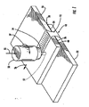
- FIG. 1 there is shown an apparatus for forming a joint 10 to connect first and second structural members 20, 22.
- Two structural members are typically joined by the method of the present invention, but a single structural member can be joined, for example, a tubular member or otherwise curved member with adjoining edges. Alternatively, three or more structural members can be joined, and the structural members can be arranged in various configurations.
- the first structural member 20 is disposed so that a faying surface 24 of the first structural member 20 overlaps a faying surface 26 of the second structural member 22 and the two structural members 20, 22 form an interface 28 therebetween.
- a friction stir welding tool is used to form a friction stir weld joint 12 between the structural members 20, 22.
- the friction stir welding tool 50 includes a rotatable pin 52 extending from a shoulder 54.
- the pin 52 is inserted through the interface 28 generally perpendicular to the interface 28, e.g., at an angle of about 3-5° from a line normal to the interface 28.
- An anvil (not shown) or other support can be disposed against the second structural member 22 to oppose the friction stir weld tool 50.
- the friction stir welding tool 50 is then urged in a direction 55 against the first structural member 20 and advanced in a direction 56 along the interface 28 of the structural members 20, 22 as the pin 52 rotates in a direction indicated by reference numeral 57.
- the motion of the pin 52 generates frictional heat, which plasticizes material from the structural members 20, 22, and the plasticized material is mixed by the pin 52.
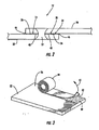
- the friction stir weld joint 12 As the plasticized material cools and hardens, the friction stir weld joint 12 is formed, the friction stir weld joint 12 comprising part of the joint 10 that connects the two structural members 20, 22 as shown in Figure 2 .
- the friction weld joint 12 includes a nugget region proximate to the path of the pin 52, the nugget region being characterized by a refined granular structure.
- the process of friction stir welding for joining structural members 20, 22 is known in the art and is described, for example, in U.S. Patent No. 5,460,317 to Thomas, et al..
- the weld joint 12 formed by the configuration shown in Figure 1 is generally referred to as a lap joint, i.e., a joint generally perpendicular to the interface of overlapping members.
- other weld joints can alternatively be formed by friction stir welding.
- the structural members 20, 22 can define any of a variety of shapes such as sheets, plates, blocks, and the like.
- the members 20, 22 can be formed of metals, such as aluminum, titanium, alloys thereof, or steel.
- the members 20, 22 can be formed of non-metallic materials, including polymers, composite materials, and the like.
- the members 20, 22 can be formed of similar or dissimilar materials, i.e., each of the members 20, 22 can be formed of the same or different materials.
- one of the members 20, 22 is formed of a metallic material and is joined to another one of the members 20, 22 that is formed of a non-metallic material.
- the members 20, 22 can be joined to create an assembly used for various applications including frames, panels, skins, airfoils, and the like for aeronautical and aerospace structures such as aircraft and spacecraft, for marine vehicles, automobiles, and the like.
- the members 20, 22 are joined in geometrical configurations that make difficult, or prevent, subsequent access for inspecting or treating the joint 10.
- the structural members 20, 22 can be overlapped and joined to form a partially or fully closed body such as a tube or an airplane wing.
- a sealant 40 is disposed between the structural members 20, 22 at the interface 28 thereof.
- the sealant 40 can be disposed on one or both of the faying surfaces 24, 26 of the structural members 20, 22, and can be disposed over part or all of the area of the interface 28, including the region of the friction stir weld joint 12.
- the sealant 40 can fill the spaces 14 between the faying surfaces 24, 26 of the structural members 20, 22.
- the sealant 40 prevents chemicals, moisture, debris, and other substances from entering the spaces 14, and the sealant 40 thereby prevents corrosion or other damage that can be caused by those substances.
- the sealant 40 is formed of a material that can be chemically reacted exothermically.
- exothermically reactable materials can include beryllium, nickel, aluminum, boron, copper, magnesium, molybdenum, palladium, rhodium, silicon, titanium, zirconium, and the like.
- the sealant 40 can be formed of compounds or mixtures of titanium and boron; aluminum, nickel, and copper; nickel and aluminum; zirconium and aluminum; nickel and silicon; molybdenum and silicon; palladium and aluminum; rhodium and aluminum; titanium and aluminum; and the like.
- the sealant 40 can be ZrAl 3 , ZrAl 2 , TiAl, a mixture of titanium and boron, or various other exothermically reactable compounds, mixtures, and materials containing elements listed above and/or others.
- the sealant 40 can also include various chemicals, e.g., to prevent or reduce oxidation of metals in the sealant 40 and/or to at least temporarily bind the members 20, 22 so that a better metallic bond results in the joint 10.
- the energy released during the exothermic reaction can be sufficient for sustaining the reaction so that once the reaction is initiated, all or substantially all of the sealant 40 in the interface 28 reacts.
- the exothermic reaction of the sealant 40 can also be sufficient for melting the sealant 40 and/or portions of the structural members 20, 22, depending on the maximum reaction temperature of the sealant 40 and the melting temperature of the structural members 20, 22.
- the structural members 20, 22 are formed of aluminum or aluminum alloys and are sealed by a sealant 40 that reaches a maximum temperature of between about 1200 °F (649 °C) and 2000 °F (1093 °C) during the exothermic reaction.
- structural members 20, 22 formed of titanium or titanium alloys are sealed by a sealant 40 that reaches a maximum temperature of between about 2000 °F (1093 °C) and 3500 °F (1927 °C) during the exothermic reaction. Unalloyed aluminum and titanium melt at temperatures of about 1220 °F (660 °C) and 3270 °F (1799 °C), respectively. Therefore, in some cases, the sealant 40 partially melts the structural members 20, 22 at the interface 28 and forms a diffusion bond therewith. Alternatively, if the reaction temperature is less than the melting temperature of the structural members 20, 22, the sealant 40 can be melted to fill the interface 28 without melting the structural members 20, 22.
- the sealant 40 can substantially fill the interface 28, thereby sealing the interface 28 and preventing the entry of debris, moisture, and the like. Further, the sealant 40 can be joined to the structural members 20, 22 forming a joint therebetween. If the sealant 40 is reacted before friction welding of the structural members 20, 22, the joint formed by the sealant 40 can hold the structural members 20, 22 in place while friction welding is performed. Further, regardless of when the sealant 40 is reacted, the joint formed by the sealant 40 can enhance the strength of the overall joint 10 between the structural members 20, 22. That is, the sealant 40 can connect the structural members 20, 22 over a portion of the interface 28 that is not joined by friction welding, thereby supplementing the strength of the friction weld joint 12.
- the sealant 40 can be formed and disposed as a film, a paste, a powder, and the like.
- the sealant 40 can be formed as a foil or film having tens, hundreds, or thousands of layers.
- the sealant 40 can be formed as a paste or other fluid, such as a powder suspended in a plasticizer fluid.
- the sealant 40 can be disposed as a film, powder, fluid, or the like onto or in a substrate 42 that is subsequently used to dispose the sealant 40 onto one or both of the faying surfaces 24, 26.
- the substrate 42 can be a thin, flexible, tape-like sheet of polymer or paper material.
- the substrate 42 can be a porous or gauze-like material, which can at least partially absorb the sealant 40 therein.
- the sealant 40 can be disposed as a layer having uniform thickness on the substrate 42, and the substrate 42 can then be coiled to form a roll 44. Subsequently, the substrate 42 can be unrolled and placed on one or both of the structural members 20, 22 with the sealant 40 between the member 20, 22 and the substrate 42.
- the sealant 40 can be disposed on the substrate 42 as the substrate 42 is dispensed from a coil and/or by a feeder device, with the substrate 42 then being positioned on the structural member(s) 20, 22.
- the substrate 42 can be peeled from the member 22 in a direction 43, leaving the sealant 40 on the faying surface 26 .
- the structural members 20, 22 can be configured for joining with the substrate 42 therebetween, and the substrate 42 can be combusted or otherwise destroyed during the exothermic reaction of the sealant 40 and/or friction welding of the structural members 20, 22.
- the amount of sealant 40 disposed on the faying surfaces 24, 26 can vary, but in one embodiment of the invention, a layer of between about 0.0005 and 0.020 inches (0.00127 and 0.0508 cm) is disposed.
- the sealant 40 can be disposed over all or part of the faying surfaces 24, 26 , including the portion of the interface 28 that is welded to form the friction weld joint 12 of the joint 10 , although in some cases the sealant 40 may positively or negatively affect certain mechanical properties of the friction weld joint 12.
- the exothermic reaction of the sealant 40 is initiated during the structural members 20, 22 are friction stir welded to form the weld joint 12 .
- the sealant 40 is disposed on the faying surfaces 24, 26 , the structural members 20, 22 are positioned so that the faying surfaces 24, 26 are opposed to define the interface 28 therebetween, and the exothermic reaction is then initiated. Initiation of the exothermic reaction is achieved by heating the sealant 40. As noted above the exothermic reaction releases sufficient thermal energy to sustain the reaction, and therefore no additional energy nedd be supplied.
- the friction stir welding is performed at least partially during the exothermic reaction.
- the sealant 40 is disposed, the structural members 20, 22 is positioned to define the interface 28, and the friction welding is then performed such that the friction welding provides sufficient thermal energy to initiate the exothermic reaction.
- the exothermic reaction can then occur at a rate that is equal to or different than the rate of the friction welding. For example, once initiated, the exothermic reaction of the sealant 40 may finish within a few seconds or less, while the friction stir welding continues at a slower rate.
- the sealant 40 substantially fills the interface 28 and thereby seals the interface 28 to prevent moisture and debris from entering the interface 28 .
- the sealant 40 can form a seal 46 that extends outside the interface 28, e.g., at one or more edges of the interface 28 to further protect the interface 28 from corrosion or other damage to the structural members 20, 22 .
- the sealant 40 can be disposed outside the interface 28 .
- the sealant 40 can be disposed on portions of the structural members 20, 22 that are extend beyond the area of the faying surfaces 24, 26 .
- the sealant 40 is disposed as a paste onto the faying surfaces 24, 26 , and the structural members 20, 22 are positioned with the faying surfaces 24, 26 in an opposed configuration to define the interface 28.
- the structural members 20, 22 are then urged together, for example, by clamping the structural members 20, 22 together.
- the paste sealant 40 substantially fills the interface 28 and some of the sealant 40 is squeezed from the interface 28 at the edges of the interface 28 . Excess paste sealant 40 can be removed from the edges of the interface 28, but some sealant 40 is left outside the interface 28.
- a bead of sealant 40 at the edge of the interface 28 forms a fillet seal 46.
- such a fillet seal 46 can alternatively be formed using conventional sealants, such as a caulk-like or resinous material.
- a braze material 48 can also be provided in the interface 28 with the sealant 40 before the sealant 40 is reacted to form a braze joint between the structural members 20, 22 .
- the braze material 48 is characterized by a melting temperature that is lower than the melting temperature of the structural members 20, 22 .
- the particular braze material 48 for a particular joint 10 can be selected according to the materials of the structural members 20, 22 and the sealant 40 .
- the braze material 48 can include bronze, copper, aluminum, and/or nickel.
- the braze material 48 can be provided as part of the foil, paste, powder, or other constitution of the sealant 40.
- thin sheets of the braze material 48 can be layered within the foil of the sealant 40 , or particles of the braze material 48 can be mixed with a sealant 40 that is a powder or paste.
- the braze material 48 can be disposed onto one or both of the faying surfaces 24, 26 together with the sealant 40.
- the braze material 48 can be provided separately in the interface 28, e.g., as a separate sheet that is layered with the foil sealant 40 , as a powder or paste that is disposed on the faying surface opposite the sealant 40, or otherwise.
- the sealant 40 can have a reaction temperature that is higher than the melting temperature of the braze material 48, and the sealant 40 can be disposed in a quantity such that sufficient heat is released during the exothermic reaction to melt the braze material 48 so that the braze material 48 is brazed or otherwise bonded to the structural members 20, 22, thereby joining the structural members 20, 22.
- the joint 12 Before, during, or after the exothermic reaction of the sealant 40 and, hence, the joining of the structural members 20, 22 by the braze material 48, the joint 12 can be formed, as described above by friction stir welding.
- the braze material 48 enhances the strength of the joint 10 between the structural members 20, 22.
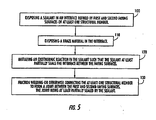
- Figure 5 illustrates the operations for forming a joint according to one embodiment of the present invention. It is understood that some of the operations can be omitted from the method, and additional operations can be performed, without departing from the scope of the present invention.
- a sealant is disposed in an interface defined by first and second faying surfaces of at least one structural member.
- the sealant can be disposed as a foil or fluid, and can be disposed with a substrate.
- the sealant can be disposed with a thickness of between about 0.0005 and 0.020 inches (0.00127 and 0.0508 cm) and can fill, or substantially fill, the entire interface.
- sealant can be disposed outside the interface, e.g., by squeezing the members together after disposing the sealant, so that the sealant forms a fillet seal outside the interface.
- a braze material is also disposed in the interface with the sealant. See Block 110.
- An exothermic reaction of the sealant is initiated so that the sealant at least partially seals the interface between the faying surfaces. See Block 120 .
- the reaction can be initiated by heating the sealant to an initiation temperature.
- the exothermic reaction is characterized by a maximum temperature of at least about 1200 °F (649 °C).
- the at least one structural member is friction stir welded to form a joint between the first and second faying surfaces, the joint being at least partially sealed by the sealant. See Block 130.
- the friction stir welding initiates the exothermic reaction of the sealant, or the sealant can be reacted before or after the friction welding.
Landscapes
- Engineering & Computer Science (AREA)
- Mechanical Engineering (AREA)
- Chemical & Material Sciences (AREA)
- Chemical Kinetics & Catalysis (AREA)
- Pressure Welding/Diffusion-Bonding (AREA)
- Building Environments (AREA)
- Lining Or Joining Of Plastics Or The Like (AREA)
Claims (26)
- Verfahren zum Bilden einer Schweißverbindung (10), wobei das Verfahren umfasst:Anordnen eines Dichtmittels (40) in einem Grenzbereich (28), der definiert wird durch eine erste und zweite Stoßfläche (24, 26) mindestens eines Bauteils (20, 22);Reibschweißen des mindestens einen Bauteils (20, 22) durch Rotieren eines sich von einer Schulter (54) erstreckenden Reibrührschweißstiftes (52) und Treiben des Stiftes (52) durch den Grenzbereich (28) und durch die Stoßflächen (24, 26) in einer Richtung im Wesentlichen senkrecht zum Grenzbereich (28), um dadurch das mindestens eine Bauteil (20, 22) zu reibrührschweißen zum Bilden einer Verbindung (10) zwischen der ersten und zweiten Stoßfläche (24, 26), wobei die Verbindung (10) von dem Dichtmittel (40) zumindest teilweise abgedichtet wird,wobei der Schritt des Reibrührschweißens das Dichtmittel (40) auf eine Initiationstemperatur des Dichtmittels (40) erwärmt und dadurch eine exotherme Reaktion im Dichtmittel (40) initiiert, so dass das Dichtmittel (40) den Grenzbereich (28) zwischen den Stoßflächen (24, 26) zumindest teilweise abdichtet.
- Verfahren nach Anspruch 1, das ferner das Vorsehen des Dichtmittels (40) umfasst, wobei das Dichtmittel (40) mindestens ein Element aus der Gruppe bestehend aus Aluminium, Nickel und Sauerstoff umfasst.
- Verfahren nach Anspruch 1 oder Anspruch 2, wobei der initiierende Schritt das Füllen im Wesentlichen des gesamten Grenzbereichs (28) mit dem Dichtmittel (40) umfasst.
- Verfahren nach einem der vorangehenden Ansprüche, wobei der Anordnungsschritt das Anordnen des Dichtmittels (40) als Folie zwischen den Stoßflächen (24, 26) umfasst.
- Verfahren nach Anspruch 4, das ferner das Bilden des Dichtmittels (40) umfasst, wobei der Bildungsschritt das Schichten einer Mehrzahl von laminaren Lagen des Dichtmittels (40) zum Bilden einer mehrschichtigen Folie umfasst.
- Verfahren nach einem der Ansprüche 1 bis 3, wobei der Anordnungsschritt das Anordnen des Dichtmittels (40) als Fluid auf mindestens einer der Stoßflächen (24, 26) umfasst.
- Verfahren nach Anspruch 6, das ferner das Vorsehen des Dichtmittels (40) als Fluid umfasst, wobei das Fluid einen Weichmacher enthält.
- Verfahren nach einem der vorangehenden Ansprüche, das ferner das Vorsehen des Dichtmittels (40) auf einem Substrat (42) umfasst, wobei der Anordnungsschritt das Anordnen des Dichtmittels (40) und des Substrats (42) auf mindestens einer der Stoßflächen (24, 26) umfasst.
- Verfahren nach Anspruch 8, das ferner das Entfernen des Substrats (42) von der Stoßfläche (24, 26) vor dem Reibschweißschritt umfasst, so dass das Dichtmittel (40) auf der Stoßfläche (24, 26) bleibt.
- Verfahren nach einem der vorangehenden Ansprüche, wobei der initiierende Schritt das Erwärmen des Dichtmittels (40) auf eine Initiationstemperatur des Dichtmittels (40) und dadurch das Initiieren der exothermen Reaktion des Dichtmittels (40) umfasst.
- Verfahren nach einem der vorangehenden Ansprüche, das ferner das Vorsehen des mindestens einen Bauteils (20, 22) umfasst, wobei das Bauteil (20, 22) mindestens ein Element aus der Gruppe bestehend aus Aluminium, Aluminiumlegierungen, Titan, Titanlegierungen und Stahl umfasst.
- Verfahren nach einem der vorangehenden Ansprüche, das ferner das Anordnen eines Lötmaterials (48) in dem Grenzbereich (28) umfasst, wobei das Lötmaterial (48) eine Schmelztemperatur aufweist, die niedriger ist als eine Schmelztemperatur des Bauteils (20, 22), und das Lötmaterial (48) während einer exothermen Reaktion des Dichtmittels (40) zumindest teilweise mit den Stoßflächen (24, 26) verbunden wird.
- Verfahren nach Anspruch 12, das ferner das Vorsehen des Lötmaterials (48) umfasst, wobei das Lötmaterial (48) mindestens ein Element aus der Gruppe bestehend aus Bronze, Kupfer, Aluminium und Nickel umfasst.
- Verfahren nach einem der vorangehenden Ansprüche, wobei der initiierende Schritt das Initiieren einer exothermen Reaktion des Dichtmittels (40) umfasst, wobei die Reaktion eine Höchsttemperatur von mindestens ca. 649°C aufweist.
- Verfahren nach einem der vorangehenden Ansprüche, wobei der Anordnungsschritt das Anordnen des Dichtmittels (40) umfasst, welches eine Dicke von zwischen ca. 0,00127 und 0,0508 cm aufweist.
- Verfahren nach einem der vorangehenden Ansprüche, wobei der initiierende Schritt das Umsetzen von mindestens einem Teil des Dichtmittels (40) außerhalb des Grenzbereichs (28) zum Bilden einer Abschlussdichtung (46) an mindestens einem Rand des Grenzbereichs (28) umfasst.
- Verfahren nach einem der vorangehenden Ansprüche, das ferner das Zusammenbringen der Stoßflächen (24, 26) vor dem initiierenden Schritt umfasst, so dass ein Teil des Dichtmittels (40) aus dem Grenzbereich (28) gedrängt und anschließend exotherm umgesetzt wird, um eine Dichtung an mindestens einem Rand des Grenzbereichs (28) zu bilden.
- Schweißverbindung (10), die eine erste und zweite Stoßfläche (24, 26) mindestens eines Bauteils (20, 22) verbindet, welche einen Grenzbereich (28) zwischen sich definieren, wobei die Schweißverbindung (10) gekennzeichnet ist durch eine Reibrührschweißverbindung (12), die die Stoßflächen (24, 26) am Grenzbereich (28) der Stoßflächen (24; 26) verbindet; und
ein exotherm umgesetztes Dichtmittel (40), das in dem Grenzbereich (28) zwischen den Stoßflächen (24, 26) an einem Abschnitt des Grenzbereichs (28) angeordnet ist, der nicht durch die Reibrührschweißverbindung (12) zusammengefügt wird und die Reibschweißverbindung (12) im Grenzbereich (28) zumindest teilweise abdichtet, wobei das exotherm umgesetzte Dichtmittel (40) aus einem Material gebildet ist, das Beryllium, Nickel, Aluminium, Bor, Kupfer, Magnesium, Molybdän, Palladium, Rhodium, Silizium, Titan oder Zirkon umfast.. - Verfahren nach Anspruch 18, wobei das Dichtmittel (40) mindestens ein Element aus der Gruppe bestehend aus Aluminium, Nickel und Sauerstoff umfasst.
- Verbindung (10) nach Anspruch 18 oder 19, wobei das Dichtmittel (40) den Grenzbereich (28) im Wesentlichen ausfüllt.
- Verbindung (10) nach einem der Ansprüche 18 bis 20, wobei das Dichtmittel (40) die Stoßflächen (24, 26) außerhalb des Grenzbereichs (28) abdichtet.
- Verbindung (10) nach einem der Ansprüche 18 bis 21, wobei die Reibschweißverbindung (12) einen körnigen Bereich umfasst, der durch Reibrührschweißen gebildet ist und durch eine feine granulare Struktur gekennzeichnet ist.
- Verbindung (10) nach einem der Ansprüche 18 bis 22, wobei sich die Reibschweißverbindung (12) durch das mindestens eine Bauteil (20, 22) in eine Richtung im Wesentlichen senkrecht zum Grenzbereich (28) erstreckt.
- Verbindung (10) nach einem der Ansprüche 18 bis 23, wobei das mindestens eine Bauteil (20, 22) aus mindestens einem Element aus der Gruppe bestehend aus Aluminium, Aluminiumlegierungen, Titan, Titanlegierungen und Stahl gebildet ist.
- Verbindung (10) nach einem der Ansprüche 18 bis 24, die ferner eine Lötverbindung (48) zwischen den Stoßflächen (24, 26) nahe der Reibschweißverbindung (12) umfasst, wobei die Lötverbindung (48) den Grenzbereich (28) zumindest teilweise abdichtet.
- Verbindung (10) nach Anspruch 25, wobei die Lötverbindung (48) aus mindestens einem Element aus der Gruppe bestehend aus Bronze, Kupfer, Aluminium und Nickel gebildet ist.
Applications Claiming Priority (2)
| Application Number | Priority Date | Filing Date | Title |
|---|---|---|---|
| US657775 | 2003-08-29 | ||
| US10/657,775 US7090112B2 (en) | 2003-08-29 | 2003-08-29 | Method and sealant for joints |
Publications (4)
| Publication Number | Publication Date |
|---|---|
| EP1510281A2 EP1510281A2 (de) | 2005-03-02 |
| EP1510281A3 EP1510281A3 (de) | 2005-06-01 |
| EP1510281B1 EP1510281B1 (de) | 2008-06-11 |
| EP1510281B2 true EP1510281B2 (de) | 2011-04-13 |
Family
ID=31978975
Family Applications (1)
| Application Number | Title | Priority Date | Filing Date |
|---|---|---|---|
| EP03027702A Expired - Lifetime EP1510281B2 (de) | 2003-08-29 | 2003-12-02 | Reibrührschweissverfahren mit einem exothermisch reagierendem Dichtmittel und eine Reibrührschweissverbindung mit einem exothermisch reagiertem Dichtmittel |
Country Status (6)
| Country | Link |
|---|---|
| US (1) | US7090112B2 (de) |
| EP (1) | EP1510281B2 (de) |
| JP (1) | JP3793536B2 (de) |
| KR (1) | KR100570312B1 (de) |
| CN (1) | CN1305630C (de) |
| DE (1) | DE60321566D1 (de) |
Families Citing this family (69)
| Publication number | Priority date | Publication date | Assignee | Title |
|---|---|---|---|---|
| DE10036170C1 (de) * | 2000-07-25 | 2001-12-06 | Eads Deutschland Gmbh | Laserunterstütztes Reibrührschweißverfahren |
| JP4134837B2 (ja) * | 2003-07-15 | 2008-08-20 | マツダ株式会社 | 摩擦接合方法および摩擦接合構造 |
| US7048175B2 (en) * | 2003-12-19 | 2006-05-23 | The Boeing Company | Friction welded structural assembly and preform and method for same |
| US7240821B2 (en) * | 2005-07-21 | 2007-07-10 | The Boeing Company | Method for joining at least two adjoining work-pieces by friction stir and/or friction stir spot welding |
| JP4846329B2 (ja) * | 2005-10-05 | 2011-12-28 | 住友軽金属工業株式会社 | 段付き重合せ材料の摩擦撹拌接合製品 |
| US20070138236A1 (en) | 2005-12-20 | 2007-06-21 | The Boeing Company | Friction stir welded assembly and associated method |
| JP5055814B2 (ja) | 2006-04-13 | 2012-10-24 | マツダ株式会社 | 接合方法及び接合装置 |
| WO2008033192A1 (en) * | 2006-09-12 | 2008-03-20 | Tosoh Smd, Inc. | Sputtering target assembly and method of making same |
| JP4968447B2 (ja) * | 2006-12-25 | 2012-07-04 | マツダ株式会社 | 金属構成部材の接合方法及びその接合構造 |
| US20080237305A1 (en) * | 2006-12-28 | 2008-10-02 | Rennick Timothy S | High-Capacity Air Cargo Pallet Using Friction Stir Welding |
| FR2911293A1 (fr) * | 2007-01-11 | 2008-07-18 | Air Liquide | Procede de soudage par friction avec apport de poudre |
| JP4924143B2 (ja) | 2007-03-28 | 2012-04-25 | マツダ株式会社 | 金属製ワークの接合方法 |
| DE102007020389B4 (de) * | 2007-04-30 | 2014-01-09 | Airbus Operations Gmbh | Fügeverfahren zum Fügen von Bauteilen im Luft- und Raumfahrtbereich |
| US7975902B2 (en) | 2007-04-30 | 2011-07-12 | Airbus Operations Gmbh | Joining method for joining components |
| US20090033040A1 (en) * | 2007-07-31 | 2009-02-05 | Vought Aircraft Industries, Inc. | Automated fiber placement mandrel joint configuration |
| US9015948B2 (en) * | 2008-01-19 | 2015-04-28 | The Boeing Company | Joining fuselage skins using friction stir welding |
| JP5365066B2 (ja) * | 2008-05-14 | 2013-12-11 | 富士電機機器制御株式会社 | 電気接触子の製造方法 |
| US8678267B2 (en) * | 2008-10-10 | 2014-03-25 | The Boeing Company | System and method for integrally forming a stiffener with a fiber metal laminate |
| US20100089977A1 (en) * | 2008-10-14 | 2010-04-15 | Gm Global Technology Operations, Inc. | Friction stir welding of dissimilar metals |
| US7997472B2 (en) * | 2008-10-14 | 2011-08-16 | GM Global Technology Operations LLC | Friction stir welding using an adhesive, copper, tin and zinc interlayer |
| CN101530947B (zh) * | 2009-04-08 | 2012-07-04 | 西安交通大学 | 一种搅拌摩擦钎焊制备双金属复合板的方法 |
| CN101579767B (zh) * | 2009-06-08 | 2011-02-09 | 重庆理工大学 | 镁合金及其复合材料非真空半固态搅拌钎焊方法 |
| CN102085599A (zh) * | 2009-12-03 | 2011-06-08 | 鸿富锦精密工业(深圳)有限公司 | 摩擦搅拌接合方法及摩擦搅拌接合产品 |
| TWI476062B (zh) * | 2010-01-29 | 2015-03-11 | Hon Hai Prec Ind Co Ltd | 摩擦攪拌接合方法 |
| TWI476061B (zh) * | 2010-01-29 | 2015-03-11 | Hon Hai Prec Ind Co Ltd | 摩擦攪拌接合方法及摩擦攪拌接合產品 |
| BR112013015743B1 (pt) * | 2010-12-06 | 2021-08-03 | Honda Motor Co., Ltd | Estrutura de armação auxiliar |
| USD762253S1 (en) * | 2011-07-29 | 2016-07-26 | Japan Transport Engineering Company | Friction stir welding tool |
| GB2505195B (en) * | 2012-08-21 | 2018-12-12 | Bae Systems Plc | Joint configuration |
| CN102825381A (zh) * | 2012-08-24 | 2012-12-19 | 北京科技大学 | 用于异种材料连接的搅拌摩擦瞬时液相扩散焊接方法 |
| CN102794563A (zh) * | 2012-08-24 | 2012-11-28 | 北京科技大学 | 用于异种材料连接的搅拌摩擦扩散焊接方法 |
| CN102794572A (zh) * | 2012-08-24 | 2012-11-28 | 北京科技大学 | 一种用于连接异种材料的搅拌摩擦熔钎焊复合焊接方法 |
| CN102794564A (zh) * | 2012-08-24 | 2012-11-28 | 北京科技大学 | 一种适用于铝合金和钛合金连接的反应搅拌摩擦焊接方法 |
| WO2014130190A1 (en) * | 2013-01-22 | 2014-08-28 | University Of Utah Research Foundation | Friction spot welding and friction seam welding |
| US8844796B1 (en) * | 2013-03-05 | 2014-09-30 | The Boeing Company | Superplastically formed ultrasonically welded metallic structure |
| CN105517749B (zh) * | 2013-12-23 | 2018-01-19 | 上海交通大学 | 摩擦焊接结构组件、水冷内燃机的缸盖、水冷内燃机以及装有水冷内燃机的机械装置 |
| EP3017905A1 (de) * | 2014-11-10 | 2016-05-11 | MAGNA STEYR Engineering AG & Co KG | Verfahren zum Verbinden zweier flächiger Bauteile |
| DE102015015762A1 (de) * | 2015-12-01 | 2017-06-01 | Kienle + Spiess Gmbh | Verfahren zur Herstellung eines aus aufeinander liegenden Lamellen bestehenden Lamellenpaketes sowie Vorrichtung zur Durchführung eines solchen Verfahrens |
| JP6505618B2 (ja) * | 2016-02-05 | 2019-04-24 | 株式会社東芝 | 摩擦攪拌接合方法および接合体 |
| CN105834608B (zh) * | 2016-05-23 | 2018-02-23 | 南昌航空大学 | 一种同步实现铝和镁异种材料搅拌摩擦点焊‑钎焊‑扩散焊的方法 |
| CN106312292B (zh) * | 2016-10-27 | 2018-11-06 | 北京世佳博科技发展有限公司 | 一种焊接方法 |
| CN109803785A (zh) * | 2017-02-22 | 2019-05-24 | 日本轻金属株式会社 | 接合方法 |
| JP6688755B2 (ja) * | 2017-03-28 | 2020-04-28 | 株式会社栗本鐵工所 | 金属薄板の接合方法及び金属薄板の接合構造 |
| JP2019013956A (ja) * | 2017-07-06 | 2019-01-31 | 神鋼溶接サービス株式会社 | 異種金属接合体の製造方法および異種金属材料の接合方法 |
| DE102017215026A1 (de) * | 2017-08-28 | 2019-02-28 | Robert Bosch Gmbh | Einpresspin für eine elektrische Kontaktieranordnung |
| CN107855618A (zh) * | 2017-10-17 | 2018-03-30 | 西安飞机工业(集团)有限责任公司 | 一种搅拌摩擦钎焊方法 |
| CN107971624A (zh) * | 2017-11-22 | 2018-05-01 | 浙江理工大学 | 一种钢板和铝板的t型连接方法 |
| US11060543B2 (en) | 2017-12-28 | 2021-07-13 | Honda Motor Co., Ltd. | Device and method of applying a sealant around a structural adhesive to prevent corrosion |
| CN108406147B (zh) * | 2018-01-23 | 2019-10-01 | 武汉理工大学 | 一种碳纤维复合材料与金属的连接方法 |
| CN108436274A (zh) * | 2018-03-06 | 2018-08-24 | 南京航空航天大学 | 一种用于蒙皮-桁条的搅拌摩擦焊与激光钎焊复合焊接工艺 |
| CN109570631B (zh) * | 2018-12-21 | 2021-04-20 | 西安建筑科技大学 | 一种搅拌摩擦加工制备多孔金属材料的方法及其加工装置 |
| CN109940260A (zh) * | 2019-03-27 | 2019-06-28 | 四川大学 | 冷喷Ti涂层辅助铝-钢异种金属搭接的搅拌摩擦焊方法 |
| JP6829343B1 (ja) * | 2019-04-24 | 2021-02-10 | 川崎重工業株式会社 | 摩擦攪拌点接合装置及びその運転方法 |
| CN110587110B (zh) * | 2019-08-07 | 2021-05-14 | 山东碳垣纳米科技有限公司 | 高熔点泡沫金属板的焊接方法及金属板 |
| CN110587112B (zh) * | 2019-09-12 | 2022-02-01 | 湖北工业大学 | 一种金属板之间的焊接方法 |
| TWI723841B (zh) * | 2020-04-09 | 2021-04-01 | 財團法人金屬工業研究發展中心 | 摩擦攪拌銲接組件及摩擦攪拌銲接加工方法 |
| CN115666908A (zh) * | 2020-05-19 | 2023-01-31 | 巴斯夫欧洲公司 | 一种金属-聚合物复合零件及其制造方法 |
| US12415229B2 (en) | 2020-07-29 | 2025-09-16 | Blue Origin Manufacturing, LLC | Friction stir welding systems and methods |
| CN112982786B (zh) * | 2021-03-09 | 2022-10-28 | 山东七星绿色建筑科技有限公司 | 一种桁架楼层板生产线及生产方法 |
| KR20220145198A (ko) * | 2021-04-21 | 2022-10-28 | 삼성전자주식회사 | 접합 구조물을 포함하는 전자 장치 |
| CN113369668B (zh) * | 2021-05-20 | 2022-08-09 | 西安交通大学 | 一种复合管/排管及复合板的搅拌摩擦硬钎焊制备方法 |
| CN114734160B (zh) * | 2022-05-11 | 2023-01-03 | 哈尔滨工业大学 | 一种点承载面密封的复合连接工艺 |
| FR3141359B1 (fr) * | 2022-10-28 | 2024-10-25 | Safran Nacelles | Procédé de soudage par friction malaxage et ensemble de soudage associé |
| US12172229B2 (en) | 2023-03-30 | 2024-12-24 | Blue Origin, Llc | Friction stir additive manufacturing devices and methods for forming in-situ rivets |
| US12246392B2 (en) | 2023-03-30 | 2025-03-11 | Blue Origin Manufacturing, LLC | Deposition head for friction stir additive manufacturing devices and methods |
| US12140109B2 (en) | 2023-03-30 | 2024-11-12 | Blue Origin, Llc | Transpiration-cooled systems having permeable and non-permeable portions |
| US12383975B2 (en) | 2023-08-03 | 2025-08-12 | Blue Origin Manufacturing, LLC | Friction stir additive manufacturing formed parts and structures with integrated passages |
| US12303994B2 (en) | 2023-08-03 | 2025-05-20 | Blue Origin Manufacturing, LLC | Friction stir additive manufacturing formed parts and structures with integrated passages |
| CN117818161A (zh) * | 2024-01-04 | 2024-04-05 | 杭州电子科技大学 | 一种铝钢过渡结构及其制造方法和应用 |
| CN117921239B (zh) * | 2024-02-27 | 2024-12-17 | 大连理工大学 | 铝合金与钢熔钎-搅拌摩擦焊铆复合连接方法 |
Citations (4)
| Publication number | Priority date | Publication date | Assignee | Title |
|---|---|---|---|---|
| FR2573346A1 (fr) † | 1984-11-16 | 1986-05-23 | Grenoble Inst Nal Polytechni | Composites de multicouches fines metal-metal et/ou metal-semi-metal |
| US5460317A (en) † | 1991-12-06 | 1995-10-24 | The Welding Institute | Friction welding |
| JP2002178170A (ja) † | 2000-12-19 | 2002-06-25 | Kobe Steel Ltd | 差厚ブランク材及びその製造方法 |
| US6543670B2 (en) † | 2001-08-29 | 2003-04-08 | The Boeing Company | Interface preparation for weld joints |
Family Cites Families (62)
| Publication number | Priority date | Publication date | Assignee | Title |
|---|---|---|---|---|
| FR622098A (fr) | 1926-07-15 | 1927-05-23 | Procédé chimique de soudure des métaux et son application | |
| US2235904A (en) * | 1938-04-04 | 1941-03-25 | Murray Corp | Seat track |
| US2232647A (en) * | 1938-05-20 | 1941-02-18 | Charles Lachman Co Inc | Textile fabric |
| US2407190A (en) * | 1944-06-30 | 1946-09-03 | Sperry Gyroscope Co Inc | Filter for fluid flow systems |
| US3233312A (en) * | 1962-08-03 | 1966-02-08 | Du Pont | Explosively bonded product |
| US3890168A (en) | 1970-09-21 | 1975-06-17 | Harold A Shumway | Exothermic welding composition |
| US3890167A (en) * | 1973-09-07 | 1975-06-17 | Kobe Steel Ltd | Method and apparatus for producing a casting having a satisfactory surface with a continuous casting operation |
| US3899306A (en) * | 1973-12-21 | 1975-08-12 | Johnson & Co Inc A | Exothermic brazing of aluminum |
| US3998374A (en) | 1975-07-11 | 1976-12-21 | Western Electric Company, Inc. | Method of forming a laminate |
| JPS54139141A (en) | 1978-04-20 | 1979-10-29 | Matsushita Electric Ind Co Ltd | Process for making plane exothermic body |
| US4871708A (en) * | 1979-03-30 | 1989-10-03 | Alloy Surfaces Company, Inc. | Pyrophorically activated iron or nickel foil and method of treating same |
| US4420509A (en) * | 1981-08-11 | 1983-12-13 | Glasteel Tennessee, Inc. | Copper-clad polyester-glass fiber laminates |
| DE3418209A1 (de) * | 1984-05-16 | 1985-11-21 | Siemens AG, 1000 Berlin und 8000 München | Verfahren zur herstellung eines metallischen koerpers unter verwendung einer amorphen legierung |
| JPS6199585A (ja) | 1984-06-01 | 1986-05-17 | Hitachi Ltd | アルミニウムメツキ鋼板の接合構造と接合方法 |
| US4640816A (en) * | 1984-08-31 | 1987-02-03 | California Institute Of Technology | Metastable alloy materials produced by solid state reaction of compacted, mechanically deformed mixtures |
| US4738389A (en) * | 1984-10-19 | 1988-04-19 | Martin Marietta Corporation | Welding using metal-ceramic composites |
| US4689104A (en) * | 1985-06-24 | 1987-08-25 | Lockheed Missiles & Space Company, Inc. | Method of bonding two substrate faces utilizing boron-silicon-hydrogen alloy films |
| JPS6221479A (ja) | 1985-07-19 | 1987-01-29 | Komatsu Ltd | レ−ザ溶接方法 |
| US4737384A (en) * | 1985-11-01 | 1988-04-12 | Allied Corporation | Deposition of thin films using supercritical fluids |
| GB8610739D0 (en) * | 1986-05-01 | 1986-06-04 | Foseco Int | Exothermic compositions |
| US4889324A (en) * | 1987-03-25 | 1989-12-26 | Erico International Corporation | Exothermic welding apparatus and method |
| US4803022A (en) * | 1987-05-06 | 1989-02-07 | Glasteel Industrial Laminates, Inc. | Method of continuously bonding and curing a zinc-coated metal-clad polyester-epoxy-glass fiber laminate |
| US4879452A (en) * | 1988-04-04 | 1989-11-07 | Erico International Corporation | Exothermic welding apparatus and method |
| US5028385A (en) * | 1989-04-10 | 1991-07-02 | Baldi Alfonso L | Treatment of metals for coating or activation |
| JPH03263781A (ja) | 1990-03-12 | 1991-11-25 | Matsushita Electric Ind Co Ltd | 面状発熱体 |
| US5551994A (en) * | 1990-05-17 | 1996-09-03 | The Boeing Company | Non-chromated oxide coating for aluminum substrates |
| CA2087473C (en) * | 1990-05-17 | 2001-10-16 | Matthias P. Schriever | Non-chromated oxide coating for aluminum substrates |
| US5472524A (en) * | 1990-05-17 | 1995-12-05 | The Boeing Company | Non-chromated cobalt conversion coating method and coated articles |
| US5468307A (en) * | 1990-05-17 | 1995-11-21 | Schriever; Matthias P. | Non-chromated oxide coating for aluminum substrates |
| US5298092A (en) * | 1990-05-17 | 1994-03-29 | The Boeing Company | Non-chromated oxide coating for aluminum substrates |
| US5411606A (en) * | 1990-05-17 | 1995-05-02 | The Boeing Company | Non-chromated oxide coating for aluminum substrates |
| US5160390A (en) * | 1990-09-12 | 1992-11-03 | Kawasaki Steel Corporation | Rapidly solidified fe-cr-al alloy foil having excellent anti-oxidation properties |
| JPH04157082A (ja) | 1990-10-16 | 1992-05-29 | Mitsubishi Heavy Ind Ltd | レーザー溶接方法 |
| GB9027802D0 (en) * | 1990-12-21 | 1991-02-13 | Ici Plc | Method of explosively bonding composite metal structures |
| US5376421A (en) * | 1991-08-30 | 1994-12-27 | University Of Cincinnati | Combustible slurry for joining metallic or ceramic surfaces or for coating metallic, ceramic and refractory surfaces |
| JPH05305447A (ja) | 1992-04-27 | 1993-11-19 | Aisin Seiki Co Ltd | 金属の箔と板材の接合方法 |
| US5855965A (en) * | 1992-11-06 | 1999-01-05 | Basf Lacke +Farben, Ag | Process for the production of a powder coating, apparatus for carrying out the process, and powder formulation for carrying out the process |
| US5670033A (en) * | 1993-04-19 | 1997-09-23 | Electrocopper Products Limited | Process for making copper metal powder, copper oxides and copper foil |
| US5381944A (en) * | 1993-11-04 | 1995-01-17 | The Regents Of The University Of California | Low temperature reactive bonding |
| US5490911A (en) * | 1993-11-26 | 1996-02-13 | The United States Of America As Represented By The Department Of Energy | Reactive multilayer synthesis of hard ceramic foils and films |
| US5419687A (en) * | 1994-02-28 | 1995-05-30 | Adahan; Carmeli | Fluid pump and suction pump assembly including same |
| US5538795B1 (en) * | 1994-07-15 | 2000-04-18 | Univ California | Ignitable heterogeneous stratified structure for the propagation of an internal exothermic chemical reaction along an expanding wavefront and method making same |
| AU3495595A (en) * | 1994-08-25 | 1996-03-22 | Qqc, Inc. | Nanoscale particles, and uses for same |
| JP2001508476A (ja) * | 1996-12-20 | 2001-06-26 | ザ・ボーイング・カンパニー | 耐食性を与えるアップリケ |
| US5873953A (en) * | 1996-12-26 | 1999-02-23 | The Boeing Company | Non-chromated oxide coating for aluminum substrates |
| FR2759759B1 (fr) * | 1997-02-17 | 1999-05-21 | Asm France Sa | Dispositif d'obturation pour vanne a membrane |
| JP3612168B2 (ja) * | 1997-03-25 | 2005-01-19 | 本田技研工業株式会社 | 部材の常温接合方法 |
| US6553911B1 (en) | 1997-04-30 | 2003-04-29 | Erico International Corporation | Exothermic reactions and methods |
| US6248184B1 (en) * | 1997-05-12 | 2001-06-19 | The Boeing Company | Use of rare earth metal salt solutions for sealing or anodized aluminum for corosion protection and paint adhesion |
| US6045028A (en) * | 1998-07-17 | 2000-04-04 | Mcdonnell Douglas Corporation | Integral corrosion protection of friction-welded joints |
| JP3262757B2 (ja) | 1998-07-23 | 2002-03-04 | 昭和電工株式会社 | 摩擦撹拌接合法 |
| US6357332B1 (en) | 1998-08-06 | 2002-03-19 | Thew Regents Of The University Of California | Process for making metallic/intermetallic composite laminate materian and materials so produced especially for use in lightweight armor |
| US6187508B1 (en) | 1998-08-14 | 2001-02-13 | Agfa-Gevaert, N.V. | Heat mode recording element based on a thin metal layer |
| US6308882B1 (en) * | 1999-09-13 | 2001-10-30 | Dana Corporation | Method for joining ductile iron and steel |
| US6432225B1 (en) | 1999-11-02 | 2002-08-13 | The Boeing Company | Non-chromated oxide coating for aluminum substrates |
| US20020012624A1 (en) | 2000-01-07 | 2002-01-31 | Figueroa Juan C. | Bulk nickel alloy catalysts and process for production of syngas |
| US6736942B2 (en) | 2000-05-02 | 2004-05-18 | Johns Hopkins University | Freestanding reactive multilayer foils |
| CN1817639A (zh) * | 2000-05-02 | 2006-08-16 | 约翰斯霍普金斯大学 | 可独立反应的多层薄片 |
| JP2002113583A (ja) | 2000-10-10 | 2002-04-16 | Kogi Corp | 摩擦圧接方法 |
| CN1173896C (zh) * | 2001-04-04 | 2004-11-03 | 西北工业大学 | SiC基复合材料与复合材料或金属材料的粘接方法 |
| AU2003258106B2 (en) | 2002-08-07 | 2009-02-05 | Eclipse Aeorospace, Inc | Method of welding, by using for example friction stir welding, surfaces with polymers sealant and welded structure |
| US7105205B2 (en) * | 2003-03-28 | 2006-09-12 | Research Foundation Of The State Of New York | Densification of thermal spray coatings |
-
2003
- 2003-08-29 US US10/657,775 patent/US7090112B2/en not_active Expired - Lifetime
- 2003-12-02 DE DE60321566T patent/DE60321566D1/de not_active Expired - Lifetime
- 2003-12-02 EP EP03027702A patent/EP1510281B2/de not_active Expired - Lifetime
- 2003-12-23 CN CNB2003101230638A patent/CN1305630C/zh not_active Expired - Lifetime
- 2003-12-23 KR KR1020030095439A patent/KR100570312B1/ko not_active Expired - Lifetime
-
2004
- 2004-01-26 JP JP2004016951A patent/JP3793536B2/ja not_active Expired - Lifetime
Patent Citations (5)
| Publication number | Priority date | Publication date | Assignee | Title |
|---|---|---|---|---|
| FR2573346A1 (fr) † | 1984-11-16 | 1986-05-23 | Grenoble Inst Nal Polytechni | Composites de multicouches fines metal-metal et/ou metal-semi-metal |
| US5460317A (en) † | 1991-12-06 | 1995-10-24 | The Welding Institute | Friction welding |
| US5460317B1 (en) † | 1991-12-06 | 1997-12-09 | Welding Inst | Friction welding |
| JP2002178170A (ja) † | 2000-12-19 | 2002-06-25 | Kobe Steel Ltd | 差厚ブランク材及びその製造方法 |
| US6543670B2 (en) † | 2001-08-29 | 2003-04-08 | The Boeing Company | Interface preparation for weld joints |
Non-Patent Citations (3)
| Title |
|---|
| BORDEAUX F.: YAVARI A.R., vol. 5, 8 August 1990, MATERIALS RESEARCH SOC, article ""Ultra rapid heating by spontaneous mixing reactions in metal-metal multilayer composites"" † |
| PATENT ABSTRACTS OF JAPAN † |
| SOPAP: ""Strong Mastic Epoxy"product information sheet", 63600 AMBERT/ FR † |
Also Published As
| Publication number | Publication date |
|---|---|
| KR100570312B1 (ko) | 2006-04-11 |
| US7090112B2 (en) | 2006-08-15 |
| EP1510281A2 (de) | 2005-03-02 |
| DE60321566D1 (de) | 2008-07-24 |
| EP1510281A3 (de) | 2005-06-01 |
| KR20050022856A (ko) | 2005-03-08 |
| JP2005074519A (ja) | 2005-03-24 |
| EP1510281B1 (de) | 2008-06-11 |
| CN1590004A (zh) | 2005-03-09 |
| US20040041006A1 (en) | 2004-03-04 |
| CN1305630C (zh) | 2007-03-21 |
| JP3793536B2 (ja) | 2006-07-05 |
Similar Documents
| Publication | Publication Date | Title |
|---|---|---|
| EP1510281B2 (de) | Reibrührschweissverfahren mit einem exothermisch reagierendem Dichtmittel und eine Reibrührschweissverbindung mit einem exothermisch reagiertem Dichtmittel | |
| EP0972605B1 (de) | Integraler Korrosionsschutz für umgerührtes Reibschweissen | |
| US6905060B2 (en) | Method and sealant for weld joints | |
| CA2514913C (en) | Out-of-position friction stir welding of high melting temperature alloys | |
| EP1745882B1 (de) | Reibrührschweissverfahren zur Verbindung von mindestens zwei Werkstücken mit Auftragen eines Klebstoffes zwischen den mindestens zwei Werkstücken | |
| EP1660270B1 (de) | Verfahren zum kombinieren von schweissen und kleben zur verbindung von metallteilen | |
| EP3680052B1 (de) | Doppeltwirkendes reibrührpunktschweissverfahren und doppeltwirkende reibrührpunktschweissvorrichtung | |
| US6227433B1 (en) | Friction welded fastener process | |
| JP2003126974A (ja) | 摩擦攪拌溶接接合部強化方法、構造アセンブリおよびその製造方法 | |
| CN101222999B (zh) | 连接至少两个板材料特别是用于轻型结构的至少两个金属板的方法以及连接和轻型结构 | |
| EP1453634A1 (de) | Verfahren und vorrichtung zum zusammenfügen von metallkomponenten, insbesondere komponenten aus leichtmetall | |
| CN106994554A (zh) | 用于将包含钢的构件与包含铝的构件相接合的方法 | |
| CN110114186A (zh) | 用于制造工件复合体的方法和工件复合体 | |
| JP4227886B2 (ja) | 摩擦攪拌接合用の金属板材の表面処理方法、表面処理金属板材、及び摩擦攪拌接合方法 | |
| Van Aken et al. | Method and Sealant for Weld Joints | |
| CN118679023A (zh) | 通过摩擦搅拌焊接接合两个阳极化元件的方法 | |
| WELDING | Wayne M Thomas |
Legal Events
| Date | Code | Title | Description |
|---|---|---|---|
| PUAI | Public reference made under article 153(3) epc to a published international application that has entered the european phase |
Free format text: ORIGINAL CODE: 0009012 |
|
| AK | Designated contracting states |
Kind code of ref document: A2 Designated state(s): AT BE BG CH CY CZ DE DK EE ES FI FR GB GR HU IE IT LI LU MC NL PT RO SE SI SK TR |
|
| AX | Request for extension of the european patent |
Extension state: AL LT LV MK |
|
| PUAL | Search report despatched |
Free format text: ORIGINAL CODE: 0009013 |
|
| AK | Designated contracting states |
Kind code of ref document: A3 Designated state(s): AT BE BG CH CY CZ DE DK EE ES FI FR GB GR HU IE IT LI LU MC NL PT RO SE SI SK TR |
|
| AX | Request for extension of the european patent |
Extension state: AL LT LV MK |
|
| 17P | Request for examination filed |
Effective date: 20050609 |
|
| AKX | Designation fees paid |
Designated state(s): DE FR GB IT SE |
|
| 17Q | First examination report despatched |
Effective date: 20051005 |
|
| 17Q | First examination report despatched |
Effective date: 20051005 |
|
| GRAP | Despatch of communication of intention to grant a patent |
Free format text: ORIGINAL CODE: EPIDOSNIGR1 |
|
| GRAS | Grant fee paid |
Free format text: ORIGINAL CODE: EPIDOSNIGR3 |
|
| GRAA | (expected) grant |
Free format text: ORIGINAL CODE: 0009210 |
|
| AK | Designated contracting states |
Kind code of ref document: B1 Designated state(s): DE FR GB IT SE |
|
| REG | Reference to a national code |
Ref country code: GB Ref legal event code: FG4D |
|
| REF | Corresponds to: |
Ref document number: 60321566 Country of ref document: DE Date of ref document: 20080724 Kind code of ref document: P |
|
| REG | Reference to a national code |
Ref country code: SE Ref legal event code: TRGR |
|
| PLBI | Opposition filed |
Free format text: ORIGINAL CODE: 0009260 |
|
| PLAX | Notice of opposition and request to file observation + time limit sent |
Free format text: ORIGINAL CODE: EPIDOSNOBS2 |
|
| 26 | Opposition filed |
Opponent name: AIRBUS SAS/AIRBUS FRANCE/AIRBUS UK LIM AIRBUS DEUT Effective date: 20090311 |
|
| PLBB | Reply of patent proprietor to notice(s) of opposition received |
Free format text: ORIGINAL CODE: EPIDOSNOBS3 |
|
| RIC2 | Information provided on ipc code assigned after grant |
Ipc: B23K 20/12 20060101AFI20101125BHEP |
|
| RTI2 | Title (correction) |
Free format text: METHOD OF FRICTION STIR WELDING USING AN EXOTHERMICALLY REACTIVE SEALANT AND FRICTION STIR WELD JOINT HAVING AN EXOTHERMICALLY REACTED SEALANT |
|
| PUAH | Patent maintained in amended form |
Free format text: ORIGINAL CODE: 0009272 |
|
| STAA | Information on the status of an ep patent application or granted ep patent |
Free format text: STATUS: PATENT MAINTAINED AS AMENDED |
|
| 27A | Patent maintained in amended form |
Effective date: 20110413 |
|
| AK | Designated contracting states |
Kind code of ref document: B2 Designated state(s): DE FR GB IT SE |
|
| REG | Reference to a national code |
Ref country code: SE Ref legal event code: RPEO |
|
| REG | Reference to a national code |
Ref country code: DE Ref legal event code: R102 Ref document number: 60321566 Country of ref document: DE Effective date: 20110413 |
|
| REG | Reference to a national code |
Ref country code: FR Ref legal event code: PLFP Year of fee payment: 13 |
|
| REG | Reference to a national code |
Ref country code: FR Ref legal event code: PLFP Year of fee payment: 14 |
|
| PG25 | Lapsed in a contracting state [announced via postgrant information from national office to epo] |
Ref country code: IT Free format text: LAPSE BECAUSE OF NON-PAYMENT OF DUE FEES Effective date: 20151202 |
|
| PG25 | Lapsed in a contracting state [announced via postgrant information from national office to epo] |
Ref country code: IT Free format text: LAPSE BECAUSE OF NON-PAYMENT OF DUE FEES Effective date: 20151202 |
|
| PGRI | Patent reinstated in contracting state [announced from national office to epo] |
Ref country code: IT Effective date: 20170710 |
|
| REG | Reference to a national code |
Ref country code: FR Ref legal event code: PLFP Year of fee payment: 15 |
|
| PGFP | Annual fee paid to national office [announced via postgrant information from national office to epo] |
Ref country code: SE Payment date: 20221227 Year of fee payment: 20 Ref country code: GB Payment date: 20221227 Year of fee payment: 20 Ref country code: FR Payment date: 20221227 Year of fee payment: 20 |
|
| PGFP | Annual fee paid to national office [announced via postgrant information from national office to epo] |
Ref country code: IT Payment date: 20221221 Year of fee payment: 20 Ref country code: DE Payment date: 20221228 Year of fee payment: 20 |
|
| P01 | Opt-out of the competence of the unified patent court (upc) registered |
Effective date: 20230503 |
|
| REG | Reference to a national code |
Ref country code: DE Ref legal event code: R071 Ref document number: 60321566 Country of ref document: DE |
|
| REG | Reference to a national code |
Ref country code: GB Ref legal event code: PE20 Expiry date: 20231201 |
|
| PG25 | Lapsed in a contracting state [announced via postgrant information from national office to epo] |
Ref country code: GB Free format text: LAPSE BECAUSE OF EXPIRATION OF PROTECTION Effective date: 20231201 |
|
| REG | Reference to a national code |
Ref country code: SE Ref legal event code: EUG |
|
| PG25 | Lapsed in a contracting state [announced via postgrant information from national office to epo] |
Ref country code: GB Free format text: LAPSE BECAUSE OF EXPIRATION OF PROTECTION Effective date: 20231201 |