EP1508509A2 - Composite member for vehicle bodies - Google Patents
Composite member for vehicle bodies Download PDFInfo
- Publication number
- EP1508509A2 EP1508509A2 EP04028020A EP04028020A EP1508509A2 EP 1508509 A2 EP1508509 A2 EP 1508509A2 EP 04028020 A EP04028020 A EP 04028020A EP 04028020 A EP04028020 A EP 04028020A EP 1508509 A2 EP1508509 A2 EP 1508509A2
- Authority
- EP
- European Patent Office
- Prior art keywords
- composite component
- film
- plastic
- upstand
- plastic layer
- Prior art date
- Legal status (The legal status is an assumption and is not a legal conclusion. Google has not performed a legal analysis and makes no representation as to the accuracy of the status listed.)
- Withdrawn
Links
Images


Classifications
-
- B—PERFORMING OPERATIONS; TRANSPORTING
- B62—LAND VEHICLES FOR TRAVELLING OTHERWISE THAN ON RAILS
- B62D—MOTOR VEHICLES; TRAILERS
- B62D27/00—Connections between superstructure or understructure sub-units
-
- B—PERFORMING OPERATIONS; TRANSPORTING
- B32—LAYERED PRODUCTS
- B32B—LAYERED PRODUCTS, i.e. PRODUCTS BUILT-UP OF STRATA OF FLAT OR NON-FLAT, e.g. CELLULAR OR HONEYCOMB, FORM
- B32B15/00—Layered products comprising a layer of metal
- B32B15/04—Layered products comprising a layer of metal comprising metal as the main or only constituent of a layer, which is next to another layer of the same or of a different material
- B32B15/046—Layered products comprising a layer of metal comprising metal as the main or only constituent of a layer, which is next to another layer of the same or of a different material of foam
-
- B—PERFORMING OPERATIONS; TRANSPORTING
- B29—WORKING OF PLASTICS; WORKING OF SUBSTANCES IN A PLASTIC STATE IN GENERAL
- B29C—SHAPING OR JOINING OF PLASTICS; SHAPING OF MATERIAL IN A PLASTIC STATE, NOT OTHERWISE PROVIDED FOR; AFTER-TREATMENT OF THE SHAPED PRODUCTS, e.g. REPAIRING
- B29C44/00—Shaping by internal pressure generated in the material, e.g. swelling or foaming ; Producing porous or cellular expanded plastics articles
- B29C44/02—Shaping by internal pressure generated in the material, e.g. swelling or foaming ; Producing porous or cellular expanded plastics articles for articles of definite length, i.e. discrete articles
- B29C44/12—Incorporating or moulding on preformed parts, e.g. inserts or reinforcements
- B29C44/1252—Removing portions of the preformed parts after the moulding step
-
- B—PERFORMING OPERATIONS; TRANSPORTING
- B29—WORKING OF PLASTICS; WORKING OF SUBSTANCES IN A PLASTIC STATE IN GENERAL
- B29C—SHAPING OR JOINING OF PLASTICS; SHAPING OF MATERIAL IN A PLASTIC STATE, NOT OTHERWISE PROVIDED FOR; AFTER-TREATMENT OF THE SHAPED PRODUCTS, e.g. REPAIRING
- B29C44/00—Shaping by internal pressure generated in the material, e.g. swelling or foaming ; Producing porous or cellular expanded plastics articles
- B29C44/02—Shaping by internal pressure generated in the material, e.g. swelling or foaming ; Producing porous or cellular expanded plastics articles for articles of definite length, i.e. discrete articles
- B29C44/12—Incorporating or moulding on preformed parts, e.g. inserts or reinforcements
- B29C44/1257—Joining a preformed part and a lining, e.g. around the edges
-
- B—PERFORMING OPERATIONS; TRANSPORTING
- B29—WORKING OF PLASTICS; WORKING OF SUBSTANCES IN A PLASTIC STATE IN GENERAL
- B29C—SHAPING OR JOINING OF PLASTICS; SHAPING OF MATERIAL IN A PLASTIC STATE, NOT OTHERWISE PROVIDED FOR; AFTER-TREATMENT OF THE SHAPED PRODUCTS, e.g. REPAIRING
- B29C44/00—Shaping by internal pressure generated in the material, e.g. swelling or foaming ; Producing porous or cellular expanded plastics articles
- B29C44/02—Shaping by internal pressure generated in the material, e.g. swelling or foaming ; Producing porous or cellular expanded plastics articles for articles of definite length, i.e. discrete articles
- B29C44/12—Incorporating or moulding on preformed parts, e.g. inserts or reinforcements
- B29C44/14—Incorporating or moulding on preformed parts, e.g. inserts or reinforcements the preformed part being a lining
- B29C44/146—Shaping the lining before foaming
-
- B—PERFORMING OPERATIONS; TRANSPORTING
- B32—LAYERED PRODUCTS
- B32B—LAYERED PRODUCTS, i.e. PRODUCTS BUILT-UP OF STRATA OF FLAT OR NON-FLAT, e.g. CELLULAR OR HONEYCOMB, FORM
- B32B27/00—Layered products comprising a layer of synthetic resin
- B32B27/06—Layered products comprising a layer of synthetic resin as the main or only constituent of a layer, which is next to another layer of the same or of a different material
- B32B27/065—Layered products comprising a layer of synthetic resin as the main or only constituent of a layer, which is next to another layer of the same or of a different material of foam
-
- B—PERFORMING OPERATIONS; TRANSPORTING
- B32—LAYERED PRODUCTS
- B32B—LAYERED PRODUCTS, i.e. PRODUCTS BUILT-UP OF STRATA OF FLAT OR NON-FLAT, e.g. CELLULAR OR HONEYCOMB, FORM
- B32B27/00—Layered products comprising a layer of synthetic resin
- B32B27/06—Layered products comprising a layer of synthetic resin as the main or only constituent of a layer, which is next to another layer of the same or of a different material
- B32B27/08—Layered products comprising a layer of synthetic resin as the main or only constituent of a layer, which is next to another layer of the same or of a different material of synthetic resin
-
- B—PERFORMING OPERATIONS; TRANSPORTING
- B32—LAYERED PRODUCTS
- B32B—LAYERED PRODUCTS, i.e. PRODUCTS BUILT-UP OF STRATA OF FLAT OR NON-FLAT, e.g. CELLULAR OR HONEYCOMB, FORM
- B32B27/00—Layered products comprising a layer of synthetic resin
- B32B27/30—Layered products comprising a layer of synthetic resin comprising vinyl (co)polymers; comprising acrylic (co)polymers
- B32B27/308—Layered products comprising a layer of synthetic resin comprising vinyl (co)polymers; comprising acrylic (co)polymers comprising acrylic (co)polymers
-
- B—PERFORMING OPERATIONS; TRANSPORTING
- B32—LAYERED PRODUCTS
- B32B—LAYERED PRODUCTS, i.e. PRODUCTS BUILT-UP OF STRATA OF FLAT OR NON-FLAT, e.g. CELLULAR OR HONEYCOMB, FORM
- B32B27/00—Layered products comprising a layer of synthetic resin
- B32B27/36—Layered products comprising a layer of synthetic resin comprising polyesters
- B32B27/365—Layered products comprising a layer of synthetic resin comprising polyesters comprising polycarbonates
-
- B—PERFORMING OPERATIONS; TRANSPORTING
- B32—LAYERED PRODUCTS
- B32B—LAYERED PRODUCTS, i.e. PRODUCTS BUILT-UP OF STRATA OF FLAT OR NON-FLAT, e.g. CELLULAR OR HONEYCOMB, FORM
- B32B5/00—Layered products characterised by the non- homogeneity or physical structure, i.e. comprising a fibrous, filamentary, particulate or foam layer; Layered products characterised by having a layer differing constitutionally or physically in different parts
- B32B5/02—Layered products characterised by the non- homogeneity or physical structure, i.e. comprising a fibrous, filamentary, particulate or foam layer; Layered products characterised by having a layer differing constitutionally or physically in different parts characterised by structural features of a fibrous or filamentary layer
- B32B5/022—Non-woven fabric
-
- B—PERFORMING OPERATIONS; TRANSPORTING
- B32—LAYERED PRODUCTS
- B32B—LAYERED PRODUCTS, i.e. PRODUCTS BUILT-UP OF STRATA OF FLAT OR NON-FLAT, e.g. CELLULAR OR HONEYCOMB, FORM
- B32B5/00—Layered products characterised by the non- homogeneity or physical structure, i.e. comprising a fibrous, filamentary, particulate or foam layer; Layered products characterised by having a layer differing constitutionally or physically in different parts
- B32B5/02—Layered products characterised by the non- homogeneity or physical structure, i.e. comprising a fibrous, filamentary, particulate or foam layer; Layered products characterised by having a layer differing constitutionally or physically in different parts characterised by structural features of a fibrous or filamentary layer
- B32B5/024—Woven fabric
-
- B—PERFORMING OPERATIONS; TRANSPORTING
- B32—LAYERED PRODUCTS
- B32B—LAYERED PRODUCTS, i.e. PRODUCTS BUILT-UP OF STRATA OF FLAT OR NON-FLAT, e.g. CELLULAR OR HONEYCOMB, FORM
- B32B5/00—Layered products characterised by the non- homogeneity or physical structure, i.e. comprising a fibrous, filamentary, particulate or foam layer; Layered products characterised by having a layer differing constitutionally or physically in different parts
- B32B5/02—Layered products characterised by the non- homogeneity or physical structure, i.e. comprising a fibrous, filamentary, particulate or foam layer; Layered products characterised by having a layer differing constitutionally or physically in different parts characterised by structural features of a fibrous or filamentary layer
- B32B5/026—Knitted fabric
-
- B—PERFORMING OPERATIONS; TRANSPORTING
- B32—LAYERED PRODUCTS
- B32B—LAYERED PRODUCTS, i.e. PRODUCTS BUILT-UP OF STRATA OF FLAT OR NON-FLAT, e.g. CELLULAR OR HONEYCOMB, FORM
- B32B5/00—Layered products characterised by the non- homogeneity or physical structure, i.e. comprising a fibrous, filamentary, particulate or foam layer; Layered products characterised by having a layer differing constitutionally or physically in different parts
- B32B5/02—Layered products characterised by the non- homogeneity or physical structure, i.e. comprising a fibrous, filamentary, particulate or foam layer; Layered products characterised by having a layer differing constitutionally or physically in different parts characterised by structural features of a fibrous or filamentary layer
- B32B5/028—Net structure, e.g. spaced apart filaments bonded at the crossing points
-
- B—PERFORMING OPERATIONS; TRANSPORTING
- B32—LAYERED PRODUCTS
- B32B—LAYERED PRODUCTS, i.e. PRODUCTS BUILT-UP OF STRATA OF FLAT OR NON-FLAT, e.g. CELLULAR OR HONEYCOMB, FORM
- B32B5/00—Layered products characterised by the non- homogeneity or physical structure, i.e. comprising a fibrous, filamentary, particulate or foam layer; Layered products characterised by having a layer differing constitutionally or physically in different parts
- B32B5/18—Layered products characterised by the non- homogeneity or physical structure, i.e. comprising a fibrous, filamentary, particulate or foam layer; Layered products characterised by having a layer differing constitutionally or physically in different parts characterised by features of a layer of foamed material
- B32B5/20—Layered products characterised by the non- homogeneity or physical structure, i.e. comprising a fibrous, filamentary, particulate or foam layer; Layered products characterised by having a layer differing constitutionally or physically in different parts characterised by features of a layer of foamed material foamed in situ
-
- B—PERFORMING OPERATIONS; TRANSPORTING
- B32—LAYERED PRODUCTS
- B32B—LAYERED PRODUCTS, i.e. PRODUCTS BUILT-UP OF STRATA OF FLAT OR NON-FLAT, e.g. CELLULAR OR HONEYCOMB, FORM
- B32B5/00—Layered products characterised by the non- homogeneity or physical structure, i.e. comprising a fibrous, filamentary, particulate or foam layer; Layered products characterised by having a layer differing constitutionally or physically in different parts
- B32B5/22—Layered products characterised by the non- homogeneity or physical structure, i.e. comprising a fibrous, filamentary, particulate or foam layer; Layered products characterised by having a layer differing constitutionally or physically in different parts characterised by the presence of two or more layers which are next to each other and are fibrous, filamentary, formed of particles or foamed
- B32B5/24—Layered products characterised by the non- homogeneity or physical structure, i.e. comprising a fibrous, filamentary, particulate or foam layer; Layered products characterised by having a layer differing constitutionally or physically in different parts characterised by the presence of two or more layers which are next to each other and are fibrous, filamentary, formed of particles or foamed one layer being a fibrous or filamentary layer
- B32B5/245—Layered products characterised by the non- homogeneity or physical structure, i.e. comprising a fibrous, filamentary, particulate or foam layer; Layered products characterised by having a layer differing constitutionally or physically in different parts characterised by the presence of two or more layers which are next to each other and are fibrous, filamentary, formed of particles or foamed one layer being a fibrous or filamentary layer another layer next to it being a foam layer
-
- B—PERFORMING OPERATIONS; TRANSPORTING
- B60—VEHICLES IN GENERAL
- B60R—VEHICLES, VEHICLE FITTINGS, OR VEHICLE PARTS, NOT OTHERWISE PROVIDED FOR
- B60R13/00—Elements for body-finishing, identifying, or decorating; Arrangements or adaptations for advertising purposes
- B60R13/02—Internal Trim mouldings ; Internal Ledges; Wall liners for passenger compartments; Roof liners
- B60R13/0212—Roof or head liners
- B60R13/0218—Roof or head liners supported by adhesion with the roof panel
-
- B—PERFORMING OPERATIONS; TRANSPORTING
- B60—VEHICLES IN GENERAL
- B60R—VEHICLES, VEHICLE FITTINGS, OR VEHICLE PARTS, NOT OTHERWISE PROVIDED FOR
- B60R13/00—Elements for body-finishing, identifying, or decorating; Arrangements or adaptations for advertising purposes
- B60R13/06—Sealing strips
-
- B—PERFORMING OPERATIONS; TRANSPORTING
- B60—VEHICLES IN GENERAL
- B60R—VEHICLES, VEHICLE FITTINGS, OR VEHICLE PARTS, NOT OTHERWISE PROVIDED FOR
- B60R13/00—Elements for body-finishing, identifying, or decorating; Arrangements or adaptations for advertising purposes
- B60R13/08—Insulating elements, e.g. for sound insulation
- B60R13/0815—Acoustic or thermal insulation of passenger compartments
-
- B—PERFORMING OPERATIONS; TRANSPORTING
- B62—LAND VEHICLES FOR TRAVELLING OTHERWISE THAN ON RAILS
- B62D—MOTOR VEHICLES; TRAILERS
- B62D25/00—Superstructure or monocoque structure sub-units; Parts or details thereof not otherwise provided for
- B62D25/06—Fixed roofs
-
- B—PERFORMING OPERATIONS; TRANSPORTING
- B62—LAND VEHICLES FOR TRAVELLING OTHERWISE THAN ON RAILS
- B62D—MOTOR VEHICLES; TRAILERS
- B62D25/00—Superstructure or monocoque structure sub-units; Parts or details thereof not otherwise provided for
- B62D25/08—Front or rear portions
- B62D25/10—Bonnets or lids, e.g. for trucks, tractors, busses, work vehicles
- B62D25/105—Bonnets or lids, e.g. for trucks, tractors, busses, work vehicles for motor cars
-
- B—PERFORMING OPERATIONS; TRANSPORTING
- B62—LAND VEHICLES FOR TRAVELLING OTHERWISE THAN ON RAILS
- B62D—MOTOR VEHICLES; TRAILERS
- B62D29/00—Superstructures, understructures, or sub-units thereof, characterised by the material thereof
- B62D29/001—Superstructures, understructures, or sub-units thereof, characterised by the material thereof characterised by combining metal and synthetic material
- B62D29/002—Superstructures, understructures, or sub-units thereof, characterised by the material thereof characterised by combining metal and synthetic material a foamable synthetic material or metal being added in situ
-
- B—PERFORMING OPERATIONS; TRANSPORTING
- B62—LAND VEHICLES FOR TRAVELLING OTHERWISE THAN ON RAILS
- B62D—MOTOR VEHICLES; TRAILERS
- B62D29/00—Superstructures, understructures, or sub-units thereof, characterised by the material thereof
- B62D29/04—Superstructures, understructures, or sub-units thereof, characterised by the material thereof predominantly of synthetic material
- B62D29/043—Superstructures
-
- B—PERFORMING OPERATIONS; TRANSPORTING
- B29—WORKING OF PLASTICS; WORKING OF SUBSTANCES IN A PLASTIC STATE IN GENERAL
- B29C—SHAPING OR JOINING OF PLASTICS; SHAPING OF MATERIAL IN A PLASTIC STATE, NOT OTHERWISE PROVIDED FOR; AFTER-TREATMENT OF THE SHAPED PRODUCTS, e.g. REPAIRING
- B29C2791/00—Shaping characteristics in general
- B29C2791/001—Shaping in several steps
-
- B—PERFORMING OPERATIONS; TRANSPORTING
- B29—WORKING OF PLASTICS; WORKING OF SUBSTANCES IN A PLASTIC STATE IN GENERAL
- B29C—SHAPING OR JOINING OF PLASTICS; SHAPING OF MATERIAL IN A PLASTIC STATE, NOT OTHERWISE PROVIDED FOR; AFTER-TREATMENT OF THE SHAPED PRODUCTS, e.g. REPAIRING
- B29C44/00—Shaping by internal pressure generated in the material, e.g. swelling or foaming ; Producing porous or cellular expanded plastics articles
- B29C44/02—Shaping by internal pressure generated in the material, e.g. swelling or foaming ; Producing porous or cellular expanded plastics articles for articles of definite length, i.e. discrete articles
- B29C44/12—Incorporating or moulding on preformed parts, e.g. inserts or reinforcements
- B29C44/14—Incorporating or moulding on preformed parts, e.g. inserts or reinforcements the preformed part being a lining
-
- B—PERFORMING OPERATIONS; TRANSPORTING
- B29—WORKING OF PLASTICS; WORKING OF SUBSTANCES IN A PLASTIC STATE IN GENERAL
- B29C—SHAPING OR JOINING OF PLASTICS; SHAPING OF MATERIAL IN A PLASTIC STATE, NOT OTHERWISE PROVIDED FOR; AFTER-TREATMENT OF THE SHAPED PRODUCTS, e.g. REPAIRING
- B29C51/00—Shaping by thermoforming, i.e. shaping sheets or sheet like preforms after heating, e.g. shaping sheets in matched moulds or by deep-drawing; Apparatus therefor
- B29C51/10—Forming by pressure difference, e.g. vacuum
-
- B—PERFORMING OPERATIONS; TRANSPORTING
- B29—WORKING OF PLASTICS; WORKING OF SUBSTANCES IN A PLASTIC STATE IN GENERAL
- B29K—INDEXING SCHEME ASSOCIATED WITH SUBCLASSES B29B, B29C OR B29D, RELATING TO MOULDING MATERIALS OR TO MATERIALS FOR MOULDS, REINFORCEMENTS, FILLERS OR PREFORMED PARTS, e.g. INSERTS
- B29K2105/00—Condition, form or state of moulded material or of the material to be shaped
- B29K2105/04—Condition, form or state of moulded material or of the material to be shaped cellular or porous
-
- B—PERFORMING OPERATIONS; TRANSPORTING
- B32—LAYERED PRODUCTS
- B32B—LAYERED PRODUCTS, i.e. PRODUCTS BUILT-UP OF STRATA OF FLAT OR NON-FLAT, e.g. CELLULAR OR HONEYCOMB, FORM
- B32B2305/00—Condition, form or state of the layers or laminate
- B32B2305/10—Fibres of continuous length
- B32B2305/18—Fabrics, textiles
-
- B—PERFORMING OPERATIONS; TRANSPORTING
- B32—LAYERED PRODUCTS
- B32B—LAYERED PRODUCTS, i.e. PRODUCTS BUILT-UP OF STRATA OF FLAT OR NON-FLAT, e.g. CELLULAR OR HONEYCOMB, FORM
- B32B2333/00—Polymers of unsaturated acids or derivatives thereof
- B32B2333/04—Polymers of esters
- B32B2333/12—Polymers of methacrylic acid esters, e.g. PMMA, i.e. polymethylmethacrylate
-
- B—PERFORMING OPERATIONS; TRANSPORTING
- B32—LAYERED PRODUCTS
- B32B—LAYERED PRODUCTS, i.e. PRODUCTS BUILT-UP OF STRATA OF FLAT OR NON-FLAT, e.g. CELLULAR OR HONEYCOMB, FORM
- B32B2369/00—Polycarbonates
-
- B—PERFORMING OPERATIONS; TRANSPORTING
- B32—LAYERED PRODUCTS
- B32B—LAYERED PRODUCTS, i.e. PRODUCTS BUILT-UP OF STRATA OF FLAT OR NON-FLAT, e.g. CELLULAR OR HONEYCOMB, FORM
- B32B2605/00—Vehicles
-
- B—PERFORMING OPERATIONS; TRANSPORTING
- B32—LAYERED PRODUCTS
- B32B—LAYERED PRODUCTS, i.e. PRODUCTS BUILT-UP OF STRATA OF FLAT OR NON-FLAT, e.g. CELLULAR OR HONEYCOMB, FORM
- B32B2605/00—Vehicles
- B32B2605/08—Cars
Definitions
- the invention relates to a composite component for vehicle bodies, especially for vehicle roofs, according to the Preamble of claim 1.
- a roof structure in the Preamble of claim 1 specified training a To achieve sufficient dent resistance, is an initially separate to manufacture torsion-resistant semi-finished profile frames, then attach to the roof skin along the edges undetachably is.
- the foamed plastic layer also covers the semi-finished profile frame permanently connected to the roof membrane. Should be made of light metal or plastic Roof skin can be stiffened effectively against denting, is after the known proposal at least one transverse to the longitudinal beams of the semi-finished profile frame extending profile strut provided.
- the well-known roof construction requires a considerable Production and material costs.
- roofs made of composite material are known (DE 32 02 594 C2), which consists of an air- and rain-proof outer layer, a medium, inherently rigid honeycomb / structural layer with aluminum or cardboard webs or semi-hard foam and Nonwoven structures, a semi-rigid, porous inner layer and a cushion and / or decorative layer by means of a H formulatepreßvons are made.
- the invention is based on the object, a relation to the generic prior art simplified, lightweight but still sufficiently stiff composite component for vehicle bodies to provide, which also produced easily can be.
- the inventive measures a composite component created for vehicle bodies, without the need for additional Profile elements for frame and struts does manage, nonetheless due to the interaction of outer skin and reinforced plastic layer obtain a bulge and total strength, the all requirements on the dimensional stability of the composite component is sufficient for all operating loads of the vehicle.
- the inventively provided non-intrinsically rigid reinforcement within the plastic layer allows for effective reinforcement the plastic layer down to the edge areas on special Way trained with a circumferential upstand Outer skin into it.
- the reinforcement is non-rigid or pliable fabrics, knitted fabrics, nonwovens, meshes, mats and the like. from, for example, glass, plastic (eg polyester or aramid) and / or carbon fibers into consideration, as far as they adapt to the shape of the outer skin into its edge regions and are penetrated and enveloped by the foaming plastic in the closed foaming mold can.
- fibers are used according to claim 2 for the formation of the reinforcement, which are incorporated as fiber length sections in a uniform distribution, but in a disordered position of the plastic layer.
- the glass fibers can according to claim 5 in lengths different lengths are used, whereby by use two different lengths with a larger proportion at the smaller length - according to claim 6 about two-thirds the amount of glass fiber - particularly good reinforcement results have been achieved.
- Length section area but can also according to claim 7 lengths uniform length are used.
- plastic film also offers the advantage that according to claim 10, the plastic in the mass in the desired Color may be colored, so that the composite component subsequently not in addition to paint is.
- the plastic film may also be used by use a highly polished thermoforming mold during production the shell-shaped outer skin a shiny surface or obtained a grained surface by previous calendering.
- an aluminum sheet as a material for the deep-drawn outer skin can protect the sheet from its hydraulic Thermoforming in the desired color finished and painted be provided with a protective film as specified in claim 14.
- the lacquer layer remains intact, as shown by peeling off the protective film.
- the paint construction can be multi-layered to the deformation of the aluminum sheet to survive without cracks or other damage.
- a primary epoxy resin based layer of about 5 to 7 microns Thickness can be a polyester-based topcoat of about 18 to 23 ⁇ m thickness, in turn, of a clear coat can be covered by PVDF of 22 microns thickness.
- the baking temperature for such a multilayer paint system is about 240 ° C.
- the hydraulic deep-drawing deformation of the finished painted aluminum sheet can be used in several stages, for example three stages, done. Thermoforming speeds of 60 mm / s have proved to be harmless to the paint system.
- the upturn of the outer skin is before edge trimming in one of them outwardly angled circumferential Flange edge over, wherein the reinforced plastic layer on the Up edge along led to the flange edge.
- the Edge trimming of the composite component for example by contour milling or laser cutting removes the angled circumferential Flange edge and the outer area of the upstand of the Outer skin as well as adhering to the sloping areas reinforced plastic layer. It stays after pruning a significant edge for the strength of the outer skin and the reinforced plastic layer at the edge of the edge receive.
- the marginal cut is both by the upstand as also guided by the reinforced plastic layer, creating a Cut surface arises when training as a vehicle roof directly on the located on the vehicle body Roof frame can be placed.
- the claim 16 is here a training variant for the circulating Upstand of the outer skin, according to the upstand in one of them outwardly angled circumferential flange passes, which on foaming the plastic layer on the inside of the outer skin of a seal over its entire Wide flat rests to between bottom and top of the Seal foam mold.
- This training variant is omitted the above-mentioned edge trimming after the foaming process altogether. Rather, can already during deep drawing of the outer skin or in a subsequent step the outwardly angled circumferential Flange edge for forming a defined termination geometry the outer skin are punched or finely cut. Of the circumferential flanged edge ensures the subsequent foaming process under flat contact with a seal of the foaming mold advantageous for a good and clean sealing of the foam mold.
- the plastic layer is as stated in claim 19 of a PUR foam, which is formed from a polyol and an isocyanate in the specified mixing ratio, namely about 1 to 2.
- the mixture of the two plastic components with the glass fiber reinforcement is carried out according to the known LFI process (L ong F iber I njection).
- the inside becomes the outer skin according to claim 20 expedient before the application of the foamable plastic for activation activated, making an excellent connection of the outer skin achieved with the foamed plastic layer.
- a decorative sheet is to be provided may this selected from the materials listed in claim 21 are and will be in the foam on the outer skin applied remote side of the plastic layer, so that it to a firm connection between the foaming plastic layer and the decorative fabric comes.
- the decorative fabric is temporary spanned on the upper part of the foaming, is from this taken into the foaming position and remains after the Removal of the tool top on the plastic layer.
- porous decorative sheet When using a porous decorative sheet is according to claim 22 provided that the sheet in itself multi-layered, wherein the sheet with a the plastic layer facing the barrier layer is provided which a penetration of the foaming plastic by the pores of the decorative fabric in its field of view prevented in.
- the composite component can advantageously already at Foaming be provided with other functional elements.
- the plastic layer may further on the remote from the outer skin Side of the plastic layer during the foaming process be foamed back a sound-absorbing surface structure, whereby the sound insulation properties of the composite component for the training of e.g. Hoods on easy Wise way to improve. Instead of or in addition to these the macrogeometry of the surface of the plastic layer.
- one of the measures the respective sound insulation requirements corresponding design the microgeometry of the facing away from the outer skin Side of the composite component as stated in claim 25, according to the on the side remote from the skin Plastic layer partially attenuation areas with reduced Density of the foam material are foamed. This foaming the attenuation ranges to the plastic layer is appropriate in a second shot, i. after foaming the plastic layer on the inside of the outer skin are the damping areas in a subsequent step to the plastic layer foamed.
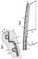
- the outer skin 1 is at its edges, from those in the figures 1 and 2 representative of the other edges only one edge is shown provided with a peripheral upstand 6, in this embodiment, first for the production the vehicle roof a greater height (Fig. 1) than after the edge trimming (Fig. 2).
- Fig. 1 goes the peripheral upstand 6 in one of them angled outwards circumferential flange 7 above, here as well as a significant part of the upstand 6 in the later edge trimming process is removed, as is clear from a comparison Figures 1 and 2.
- the foaming mold shown in Fig. 1 consists of a the deep-drawn outer skin 1 form-fitting receiving lower part. 8 and a complementary upper part 9, in the edge region of a inflatable circumferential seal 10 is arranged, which for a boundary of the foaming the plastic layer 2 forming Plastic ensures.
- the decorative sheet 3 is in tensioned form by means of a groove 11 in the upper part 9 inserted tenter 12 temporarily on the upper part 9 attached to the foaming mold.
- foam plastic is For example, a foam system used by Elastogran, consisting of polyol B 237 and isocyanate E 3509, these being two components in the mixing ratio of 100 parts of polyol to be applied to 210 parts of isocyanate.
- the outer circumferential upstand 6 has in this Embodiment, the outer skin 1 and an inner circumferential Upstand 13, which is in the same direction as the upstand 6 is angled and in the finished state of the vehicle roof limited a roof opening, which by means of a not shown Sliding lid can be optionally covered.
- the as described reinforced plastic layer 2 extends to the upstands 6 and 13 zoom, whereby the vehicle roof a sufficient rigidity is obtained.
- EPDM Seals 16 with suitable cross section at the ends of Upstands 6, 13 and at end portions 17, 18 of the guide profile 14 in the lower part 8 and in the upper part 9 of the foam mold intended.
- the groove 19 is used in assembly of the modular Vehicle roof on the vehicle receiving an adhesive bead, by means of the vehicle roof on the vehicle-side roof frame is fastened while the support surface 20 mounted in the Condition of the vehicle roof the roof frame defined rests.
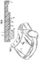
- the third embodiment shown in Fig. 4 differs from that described with reference to FIG second embodiment in that the upstand 6 of the Outer skin 1 in one of them outwardly angled circumferential Flange edge 21 passes.
- the peripheral flange edge 21 is so short formed so that it foams the armored plastic layer 2 on the inside of the outer skin 1 of the seal 16 in Upper part 9 of the foam mold rests flat over its entire width. Since the flange edge 21 while the lower part 8 of the foam mold rests, it is in the closed state of the foam mold pressed into the seal 16.
- the foaming mold becomes for the foaming between the lower part 8 and the Upper part 9 reliably sealed, without the risk that the upstand 6 and the flange 21, the seal 16 damaged.
- a border trim of the outer skin 1 before this in the lower part 8 of the foaming mold is inserted.
- the edge trimming can be done simultaneously with the thermoforming of the outer skin 1 or in a subsequent step to do this by punching or fine blanking.
- the seal 22 is already during foaming the plastic layer 2 on the already edge-cut outer skin 1 foamed with the plastic layer 2, and indeed with her inner thigh 23, but only over a part of the total height of the upstand 6 extends so that the Armored plastic layer 2 also extend to the upstand 6 can.
- the seal 22 advantageously already serves as a sealing element between the lower part 8 and the upper part 9 of the foam mold.
- the outer limb 24 forms the seal 22 in the vehicle body mounted state the vehicle roof on the one hand a sealing surface to between Seal vehicle roof and roof frame 4.
- the outer leg 24 of the seal 22 due to its Elasticity a the vehicle roof with respect to the roof frame. 4 centering effect.
- the seal 22 is otherwise made a material containing the particular thermal and mechanical Stresses in the foaming mold and on the vehicle sufficiently resist the assembled state of the vehicle roof can, e.g. Foam rubber or EPDM.
- Fig. 6 illustrates Finally, how the vehicle roof by means of a groove 19 recorded adhesive bead 25 with the roof frame 4 of Vehicle body is connected.
- FIGS. 7 and 8 still a hood shown, the deep-drawn outer skin 1 'frameless formed at their edges and with a circumferential upstand 6 'is provided, with the on the inside the outer skin 1 'foamed plastic layer 2', in the over the entire area of the outer skin 1 'a per se not rigid reinforcement is provided, up to the circulating Upstand 6 'is enough.
- a composite component in particular vehicle roof, consisting of a deep-drawn outer skin Sheet metal or plastic foil and one of the inside of the Outer skin foamed plastic layer.
- the plastic layer has an internal reinforcement through it in even Distribution of incorporated fibers, preferably glass fibers, which the composite component in cooperation with the outer skin of a considerable dimensional stability and strength to lend. It is essential that the fiber-reinforced plastic layer also reinforced an edge Aufkantung the outer skin.
Abstract
Description
Die Erfindung bezieht sich auf ein Verbundbauteil für Fahrzeugkarosserien,
insbesondere für Fahrzeugdächer, entsprechend dem
Oberbegriff des Patentanspruchs 1.The invention relates to a composite component for vehicle bodies,
especially for vehicle roofs, according to the
Preamble of
Erfindungsgemäß ausgebildete Verbundbauteile sind grundsätzlich für alle Flächenbereiche von Fahrzeugkarosserien, einschließlich der Hauben, Türen und Klappen/Deckel, geeignet, für die neben einer ausreichenden Beulsteifigkeit und Festigkeit wie Biegefestigkeit und Torsionsfestigkeit bei geringem Gewicht gute Wärme- und/oder Schallisolationseigenschaften verlangt werden. Wenn nachfolgend von einem Fahrzeugdach bzw. einer Motorhaube die Rede ist, handelt es sich zwar um bevorzugte Anwendungsorte der Erfindung, jedoch ohne darauf einschränkende Bedeutung.Composite components formed according to the invention are basically for all areas of vehicle bodies, including the hoods, doors and flaps / covers, suitable for the in addition to a sufficient dent resistance and strength such as Flexural strength and torsional strength with low weight requires good heat and / or sound insulation properties become. If subsequently from a vehicle roof or hood it is true that these are preferred places of application of the invention, but without limitation Importance.
Um bei einem bekannten Dachaufbau (GM 79 29 367 U1) der im
Oberbegriff des Patentanspruchs 1 angegebenen Ausbildung eine
ausreichende Beulsteifigkeit zu erreichen, ist ein zunächst getrennter
verwindungssteifer Halbzeug-Profilrahmen anzufertigen,
der dann an der Dachhaut längs deren Rändern unlösbar zu befestigen
ist. Die aufgeschäumte Kunststoffschicht überdeckt auch
den mit der Dachhaut unlösbar verbundenen Halbzeug-Profilrahmen.
Soll eine aus Leichtmetall oder aus Kunststoff bestehende
Dachhaut wirksam gegen Einbeulung versteift werden, ist nach
dem bekannten Vorschlag wenigstens eine sich quer zu den Längsholmen
des Halbzeug-Profilrahmens erstreckende Profilstrebe
vorzusehen. Der bekannte Dachaufbau erfordert einen erheblichen
Fertigungs- und Materialaufwand.In a known roof structure (GM 79 29 367 U1) in the
Preamble of
Entsprechendes gilt für die aus der GB 2 311 966 A bekannten Verbundbauteile für Fahrzeugkarosserien. Gemäß diesem Stand der Technik werden eine äußere Schale und eine innere Schale für das Verbundbauteil mittels Spritzgießen aus Kunststoff hergestellt und in einem Folgeschritt durch einen Kunststoffschweißvorgang oder unter Zuhilfenahme von Klebstoff entlang ihrer Ränder fest und dicht miteinander verbunden. Dann wird der entstandene Hohlkörper mit einer aushärtenden Füllung aus Kunststoff gefüllt. Alternativ dazu kann auch ein Füllkörper vorgefertigt werden, der zwischen der äußeren und der inneren Schale einzufügen ist, wenn diese miteinander verbunden werden. Für höhere Festigkeitserfordernisse sind Versteifungsteile aus Aluminium im Hohlraum zwischen äußerer und innerer Schale vorzusehen, wobei die äußere Schale mit Kanälen zur Aufnahme der Versteifungsteile ausgebildet ist.The same applies to those known from GB 2 311 966 A. Composite components for vehicle bodies. According to this state of Technique will be an outer shell and an inner shell for the composite component made by injection molding of plastic and in a subsequent step by a plastic welding process or with the help of adhesive along her Edges firmly and tightly connected. Then the resulting Hollow body with a hardening filling made of plastic filled. Alternatively, a filler can be prefabricated be that between the outer and the inner shell is to be inserted when these are linked together. For Higher strength requirements are stiffening parts made of aluminum to provide in the cavity between the outer and inner shell, the outer shell having channels for receiving the stiffening parts is trained.
Schließlich sind auch Dächer aus Verbundwerkstoff bekannt (DE 32 02 594 C2), die aus einer luft- und regendichten Außenschicht, einer mittleren, eigensteifen Waben-/Strukturschicht mit Aluminium- oder Pappstegen bzw. halbharten Schaum- und Vliesstrukturen, einer halbsteifen, porösen Innenschicht und einer Polster- und/oder Dekorschicht mittels eines Heißpreßverfahrens gefertigt sind.Finally, roofs made of composite material are known (DE 32 02 594 C2), which consists of an air- and rain-proof outer layer, a medium, inherently rigid honeycomb / structural layer with aluminum or cardboard webs or semi-hard foam and Nonwoven structures, a semi-rigid, porous inner layer and a cushion and / or decorative layer by means of a Heißpreßverfahrens are made.
Der Erfindung liegt die Aufgabe zugrunde, ein gegenüber dem gattungsbildenden Stand der Technik vereinfachtes, leichtes aber dennoch ausreichend steifes Verbundbauteil für Fahrzeugkarosserien bereitzustellen, welches auch einfach hergestellt werden kann.The invention is based on the object, a relation to the generic prior art simplified, lightweight but still sufficiently stiff composite component for vehicle bodies to provide, which also produced easily can be.
Die gestellte Aufgabe wird durch die im Anspruch 1 angegebenen
Merkmale gelöst. Vorteilhafte und/oder zweckmäßige Weiterbildungen
gehen aus den Unteransprüchen 2 bis 25 hervor und werden
nachfolgend ebenfalls erläutert.The stated object is specified by the
Erfindungsgemäß ist bei einem Verbundbauteil für Fahrzeugkarosserien, welches eine tiefgezogene Außenhaut und eine der Innenseite der Außenhaut aufgeschäumte Kunststoffschicht aufweist, die auf ihrer Oberfläche ggf. mit einem textilen Flächengebilde oder einer dekorativen Kunststoffolie versehen ist, die Außenhaut an ihren Rändern rahmenlos ausgebildet und mit einer umlaufenden Aufkantung versehen, wobei die geschäumte Kunststoffschicht bis zu der Aufkantung reicht und in der geschäumten Kunststoffschicht über den gesamten Flächenbereich der Außenhaut eine an sich nicht steife Armierung vorgesehen ist, durch welche der Elastizitätsmodul der geschäumten Kunststoffschicht erhöht ist.According to the invention, in a composite component for vehicle bodies, which is a deep-drawn outer skin and one of the inside the skin has foamed plastic layer, on their surface if necessary with a textile fabric or a decorative plastic film is provided, the outer skin frameless at their edges and with a circumferential Aufkantung provided, wherein the foamed plastic layer reaches up to the upstand and in the foamed Plastic layer over the entire area of the outer skin a per se not rigid reinforcement is provided by which is the modulus of elasticity of the foamed plastic layer is increased.
Durch die erfindungsgemäßen Maßnahmen wird ein Verbundbauteil für Fahrzeugkarosserien geschaffen, das ohne aufwendige zusätzliche Profilelemente für Rahmen und Streben auskommt, dennoch aufgrund des Zusammenwirkens von Außenhaut und armierter Kunststoffschicht eine Beulsteifigkeit und Gesamtfestigkeit erhält, die allen Anforderungen an die Formstabilität des Verbundbauteils bei allen Betriebsbeanspruchungen des Fahrzeugs genügt. Die erfindungsgemäß vorgesehene nicht eigensteife Armierung innerhalb der Kunststoffschicht ermöglicht eine wirksame Armierung der Kunststoffschicht bis in die Randbereiche der auf besondere Weise mit einer umlaufenden Aufkantung ausgebildeten Außenhaut hinein.The inventive measures a composite component created for vehicle bodies, without the need for additional Profile elements for frame and struts does manage, nonetheless due to the interaction of outer skin and reinforced plastic layer obtain a bulge and total strength, the all requirements on the dimensional stability of the composite component is sufficient for all operating loads of the vehicle. The inventively provided non-intrinsically rigid reinforcement within the plastic layer allows for effective reinforcement the plastic layer down to the edge areas on special Way trained with a circumferential upstand Outer skin into it.
Als Armierung kommen nichteigensteife bzw. biegeschlaffe Gewebe,
Gewirke, Vliese, Gitter, Matten u.dgl. aus beispielsweise
Glas-, Kunststoff- (z.B. Polyester- oder Aramid-) und/oder
Kohle-Fasern in Betracht, soweit sie sich der Form der Außenhaut
bis in deren Randbereiche hinein anpassen und von dem aufschäumenden
Kunststoff in dem geschlossenen Schäumwerkzeug
durchdrungen und umhüllt werden können. Vorzugsweise werden
aber gemäß Anspruch 2 Faserstoffe für die Bildung der Armierung
verwendet, welche als Faserlängenabschnitte in gleichmäßiger
Verteilung, aber in ungeordneter Lage der Kunststoffschicht
einverleibt sind. Besonders gute Ergebnisse wurden durch Verwendung
einer Armierung aus Glasfaserstoffen gemäß Anspruch 3
erzielt, die in Längenabschnitten von verdrillten Glasfaserbündeln
von etwa 4800 tex zwischen ca. 12,5 mm und ca. 100 mm
Länge vorliegen. Der Elastizitätsmodul des geschäumten Kunststoffes,
der ohne diese Armierung etwa einen Wert von 300 N/mm2
aufweist, konnte entsprechend Anspruch 4 bei Einbringung einer
Glasfaserarmierung von 25 Gew.% bezogen auf das Gesamtgewicht
des armierten Kunststoffschaums auf über 1600 N/mm2 erhöht werden.The reinforcement is non-rigid or pliable fabrics, knitted fabrics, nonwovens, meshes, mats and the like. from, for example, glass, plastic (eg polyester or aramid) and / or carbon fibers into consideration, as far as they adapt to the shape of the outer skin into its edge regions and are penetrated and enveloped by the foaming plastic in the closed foaming mold can. Preferably, however, fibers are used according to
Die Glasfaserstoffe können gemäß Anspruch 5 in Längenabschnitten
unterschiedlicher Länge verwendet werden, wobei durch Verwendung
zweier unterschiedlicher Längen mit einem größeren Anteil
an der kleineren Länge - gemäß Anspruch 6 etwa zwei Drittel
der Glasfasermenge - besonders gute Armierungsergebnisse
erzielt worden sind. Im Rahmen des im Anspruch 3 angegebenen
Längenabschnittsbereichs können aber auch nach Anspruch 7 Längenabschnitte
einheitlicher Länge zum Einsatz kommen.The glass fibers can according to claim 5 in lengths
different lengths are used, whereby by use
two different lengths with a larger proportion
at the smaller length - according to
Für die Außenhaut eignen sich metallische Werkstoffe wie Stahloder
Aluminiumbleche. Aber auch die Verwendung einer vakuumtiefgezogenen
Außenhaut aus einer thermoplastischen Kunststofffolie,
vorzugsweise einer zweischichtigen Koextrusionsfolie gemäß
Anspruch 8, ergibt ein Verbundbauteil überzeugender Stabilität.
Die Koextrusionsfolie besteht vorteilhaft aus den im Anspruch
9 angegebenen Werkstoffen, nämlich PMMA für die äußere
Schicht sowie einer Mischung aus PC und ASA für die innere
Schicht, und weist die dort angegebenen Schichtdickenverhältnisse
auf, wonach die Dicke der äußeren Schicht vorzugsweise
etwa 15 % der Gesamtdicke der Außenhaut ausmacht. Beispielsweise
beträgt die Gesamtdicke der Koextrusionsfolie etwa 1,3
mm, wovon etwa 0,2 mm auf die äußere Schicht entfallen.For the outer skin are suitable metallic materials such as steel or
Aluminum sheets. But also the use of a vacuum-drawn
Outer skin made of a thermoplastic film,
preferably a two-layer coextrusion film according to
Die Verwendung einer Kunststoffolie bietet auch den Vorteil,
daß gemäß Anspruch 10 der Kunststoff in der Masse in der gewünschten
Farbe durchgefärbt sein kann, so daß das Verbundbauteil
nachträglich nicht zusätzlich zu lackieren ist. Wie im Anspruch
11 angegeben kann die Kunststoffolie außerdem durch Verwendung
einer hochglanzpolierten Tiefziehform bei Herstellung
der schalenförmigen Außenhaut eine glänzende Oberfläche oder
durch vorhergehendes Kalandrieren eine genarbte Oberfläche erhalten.The use of a plastic film also offers the advantage
that according to
Wenn die Außenhaut gemäß Anspruch 12 aus einem dünnen Aluminiumblech
geformt ist, kann dessen Dicke dank der armierten
Kunststoffschicht im Interesse einer Gewichtsersparnis verhältnismäßig
gering sein, vorzugsweise ca. 0,6 mm. Für die Außenhaut
besonders geeignet ist die im Anspruch 13 angegebene Aluminiumlegierung
AlMg 0,4 Si 1,2.If the outer skin according to claim 12 of a thin aluminum sheet
its thickness can be thanks to the reinforced
Plastic layer in the interest of weight savings relatively
be low, preferably about 0.6 mm. For the outer skin
Particularly suitable is the aluminum alloy specified in
Bei Verwendung eines Aluminiumblechs als Werkstoff für die
tiefgezogene Außenhaut kann das Blech vor seiner hydraulischen
Tiefziehverformung in der gewünschten Farbe fertig lackiert und
mit einer Schutzfolie versehen sein, wie im Anspruch 14 angegeben.
Bei der Tiefziehverformung bleibt die Lackschicht unversehrt,
wie sich nach Abziehen der Schutzfolie zeigt. Der Lackaufbau
kann mehrschichtig sein, um die Verformung des Aluminiumblechs
ohne Risse oder sonstige Beschädigungen zu überstehen.
Auf einer Primärschicht auf Epoxydharzbasis von etwa 5 bis 7 µm
Dicke kann ein Decklack auf Polyesterbasis von etwa 18 bis 23
µm Dicke aufgetragen sein, der wiederum von einer Klarlackschicht
aus PVDF von 22 µm Dicke überdeckt sein kann. Die Einbrenntemperatur
für einen derartigen mehrschichtigen Lackaufbau
beträgt etwa 240°C. Die hydraulische Tiefziehverformung des
fertig lackierten Aluminiumblechs kann in mehreren Stufen, beispielsweise
drei Stufen, erfolgen. Tiefziehgeschwindigkeiten
von 60 mm/s haben sich als unschädlich für den Lackaufbau erwiesen. When using an aluminum sheet as a material for the
deep-drawn outer skin can protect the sheet from its hydraulic
Thermoforming in the desired color finished and painted
be provided with a protective film as specified in
Nach Anspruch 15 geht die Aufkantung der Außenhaut vor Randbeschnitt
in einen davon nach außen abgewinkelten umlaufenden
Flanschrand über, wobei die armierte Kunststoffschicht an der
Aufkantung entlang bis auf den Flanschrand geführt ist. Das
Randbeschneiden des Verbundbauteils beispielsweise durch Konturfräsen
oder Laserschnitt entfernt den abgewinkelten umlaufenden
Flanschrand und den äußeren Bereich der Aufkantung der
Außenhaut sowie die an den dabei abfallenden Bereichen anhaftende
armierte Kunststoffschicht. Es bleibt nach dem Beschneiden
ein für die Festigkeit erheblicher Aufkantungsrand der Außenhaut
und die armierte Kunststoffschicht am Aufkantungsrand
erhalten. Der Randschnitt wird sowohl durch die Aufkantung als
auch durch die armierte Kunststoffschicht geführt, wodurch eine
Schnittfläche entsteht, die bei einer Ausbildung als Fahrzeugdach
unmittelbar auf den an der Fahrzeugkarosserie befindlichen
Dachrahmen aufgesetzt werden kann.According to
Der Anspruch 16 gibt hier eine Ausbildungsvariante für die umlaufende
Aufkantung der Außenhaut an, gemäß der die Aufkantung
in einen davon nach außen abgewinkelten umlaufenden Flanschrand
übergeht, welcher beim Aufschäumen der Kunststoffschicht auf
der Innenseite der Außenhaut einer Dichtung über seine gesamte
Breite flächig anliegt, um zwischen Unterteil und Oberteil der
Schäumform abzudichten. Bei dieser Ausbildungsvariante entfällt
das oben angesprochene Randbeschneiden nach dem Schäumvorgang
gänzlich. Vielmehr kann bereits beim Tiefziehen der Außenhaut
oder in einem Folgeschritt der nach außen abgewinkelte umlaufende
Flanschrand zur Ausbildung einer definierten Abschlußgeometrie
der Außenhaut gestanzt oder feingeschnitten werden. Der
umlaufende Flanschrand sorgt bei dem dann folgenden Schäumvorgang
unter flächiger Anlage an einer Dichtung der Schäumform
vorteilhaft für eine gute und saubere Abdichtung der Schäumform.
Zwar ist es grundsätzlich möglich, daß die Außenhaut vor
dem Schäumvorgang nur eine umlaufende Aufkantung aufweist, ohne
einen davon nach außen abgewinkelten Flanschrand, der ggf. bereits
entfernt wurde. Jedoch gestaltet sich dann die Abdichtung
der Schäumform schwieriger, insbesondere kann die scharfe Abschlußkante
der Aufkantung einen negativen Einfluß auf die
Standzeit der Dichtung der Schäumform haben.The
Nach einer besonders vorteilhaften Ausgestaltung des Verbundbauteils
gemäß Anspruch 17 ist auf die Aufkantung der tiefgezogenen
Außenhaut eine Dichtung aufgesteckt, die einen zweischenkligen,
im wesentlichen U-förmigen Querschnitt aufweist,
wobei der innere Schenkel der Dichtung an die Kunststoffschicht
angeschäumt ist, während der äußere Schenkel die Dichtungsfläche
bildet. Im Ergebnis ist das Verbundbauteil nach dem Aufschäumen
der Kunststoffschicht auf der Innenseite der Außenhaut
in vorteilhafter Weise bereits mit einer integrierten Dichtung
versehen, die das Verbundbauteil gegenüber angrenzenden Karosseriebauteilen
abdichtet, ohne daß dazu weitere Arbeitsschritte,
beispielsweise das Aufstecken einer zusätzlichen,
zunächst getrennt bereitzustellenden Dichtung auf das fertige
Verbundbauteil vonnöten wären, was weitere Kosteneinsparungen
mit sich bringt. Diese Ausgestaltung bietet noch den zusätzlichen
Vorteil, daß die Dichtung schon beim Schäumvorgang zwischen
dem Unterteil und dem Oberteil der Schäumform abdichten
kann, wie im Anspruch 18 angegeben, so daß an dieser Stelle in
der Schäumform keine Dichtung vorgesehen werden muß, die durch
wiederholten Gebrauch verschleißen würde.According to a particularly advantageous embodiment of the composite component
according to claim 17 is on the upstand of the deep-drawn
Outer skin is a seal attached, which is a two-legged,
has a substantially U-shaped cross-section,
wherein the inner leg of the seal to the plastic layer
is foamed, while the outer leg of the sealing surface
forms. As a result, the composite component is after foaming
the plastic layer on the inside of the outer skin
advantageously already with an integrated seal
provided that the composite component against adjacent body components
seals, without further steps,
for example, attaching an additional,
initially separately to be provided seal on the finished
Composite component would be needed, resulting in further cost savings
brings with it. This embodiment still offers the additional
Advantage that the seal already during the foaming between
Seal the lower part and the upper part of the foaming mold
can, as stated in
Die Kunststoffschicht besteht wie im Anspruch 19 angegeben aus
einem PUR-Schaum, der aus einem Polyol und einem Isocyanat im
angegebenen Mischungsverhältnis, nämlich etwa 1 zu 2, gebildet
ist. Die Mischung der beiden Kunststoffkomponenten mit der
Glasfaserarmierung erfolgt nach dem bekannten LFI-Verfahren
(Long Fiber Injection).The plastic layer is as stated in
Die im Mischkopf durchmischte flüssige Kunststoff/Glasfaser-Masse wird hierbei auf die mit ihrer Innenseite nach oben weisend in das Unterteil des Schäumwerkzeugs eingelegte tiefgezogene Außenhaut.etwa in deren Mitte beginnend über einen etwa spiralförmigen Weg aufgetragen, bevor das Werkzeugoberteil in die der vorgesehenen Dicke der geschäumten Kunststoffschicht entsprechende Position oberhalb des Werkzeugunterteils gebracht wird. Der auftreibende Schaum füllt die Form und dringt bis in die ggf. später zu beschneidenden Randbereiche der Außenhaut, jedenfalls bis zur umlaufenden Aufkantung der Außenhaut vor.The mixed in the mixing head liquid plastic / glass fiber mass is hereby pointing to the with its inside up in the lower part of the foaming tool inserted deep-drawn Außenhaut.etwa in the middle starting over an approximately applied spiral way before the tool shell in the intended thickness of the foamed plastic layer corresponding position brought above the mold base becomes. The foaming foam fills the mold and penetrates into the marginal areas of the outer skin, which may later have to be trimmed, in any case, up to the peripheral Aufkantung the outer skin before.
Wird eine Kunststoffolie als Außenhaut verwendet, wird die Innenseite der Außenhaut entsprechend Anspruch 20 zweckmäßig vor dem Auftragen des schäumbaren Kunststoffs zur Aktivierung abgeflämmt, wodurch eine ausgezeichnete Verbindung der Außenhaut mit der geschäumten Kunststoffschicht erzielt wird.If a plastic film is used as the outer skin, the inside becomes the outer skin according to claim 20 expedient before the application of the foamable plastic for activation activated, making an excellent connection of the outer skin achieved with the foamed plastic layer.
Falls auf der Oberfläche der aufgeschäumten Kunststoffschicht
ein dekoratives Flächengebilde vorgesehen werden soll, kann
dieses aus den im Anspruch 21 aufgeführten Materialien ausgewählt
werden und wird in der Schäumform auf die der Außenhaut
abgelegene Seite der Kunststoffschicht aufgebracht, so daß es
zu einer festen Verbindung zwischen der aufschäumenden Kunststoffschicht
und dem dekorativen Flächengebilde kommt. Zweckmäßig
ist hierbei das dekorative Flächengebilde vorübergehend
an dem Oberteil des Schäumwerkzeugs aufgespannt, wird von diesem
in die Schäumposition mitgenommen und verbleibt nach der
Entfernung des Werkzeugoberteils auf der Kunststoffschicht.If on the surface of the foamed plastic layer
a decorative sheet is to be provided may
this selected from the materials listed in
Bei Verwendung eines porösen dekorativen Flächengebildes ist
gemäß Anspruch 22 vorgesehen, daß das Flächengebilde in sich
mehrschichtig aufgebaut ist, wobei das Flächengebilde mit einer
der Kunststoffschicht zugekehrten Sperrschicht versehen ist,
welche ein Durchschlagen des aufschäumenden Kunststoffs durch
die Poren des dekorativen Flächengebildes in dessen Sichtbereich
hinein verhindert. When using a porous decorative sheet is
according to
Das Verbundbauteil kann in vorteilhafter Weise schon beim
Schäumvorgang mit weiteren Funktionselementen versehen werden.
So stellt der Anspruch 23 auf ein Verbundbauteil für insbesondere
ein Fahrzeugdach ab, dessen Außenhaut eine Öffnung aufweist,
wobei auf der von der Außenhaut abgelegenen Seite der
Kunststoffschicht ein Führungsprofil für einen die Öffnung
wahlweise verschließenden Schiebedeckel angeschäumt ist.The composite component can advantageously already at
Foaming be provided with other functional elements.
Thus, the
Gemäß Anspruch 24 kann weiterhin auf der von der Außenhaut abgelegenen
Seite der Kunststoffschicht schon beim Schäumvorgang
eine schallabsorbierende Oberflächenstruktur hinterschäumt werden,
wodurch sich die Schallisolationseigenschaften des Verbundbauteils
für die Ausbildung von z.B. Motorhauben auf einfache
Weise noch verbessern lassen. Anstelle von oder zusätzlich
zu diesen die Makrogeometrie der Oberfläche der Kunststoffschicht
betreffenden Maßnahmen kann schließlich auch eine
den jeweiligen Schallisolationserfordernissen entsprechende Gestaltung
der Mikrogeometrie der von der Außenhaut abgewandten
Seite des Verbundbauteils erfolgen, wie im Anspruch 25 angegeben,
gemäß dem auf der von der Außenhaut abgelegenen Seite der
Kunststoffschicht partiell Dämpfungsbereiche mit verminderter
Dichte des Schaummaterials angeschäumt sind. Dieses Anschäumen
der Dämpfungsbereiche an die Kunststoffschicht erfolgt zweckmäßig
in einem zweiten Schuß, d.h. nach Aufschäumen der Kunststoffschicht
auf der Innenseite der Außenhaut werden die Dämpfungsbereiche
in einem Folgeschritt an die Kunststoffschicht
angeschäumt.According to
Im folgenden wird die Erfindung anhand bevorzugter Ausführungsbeispiele unter Bezugnahme auf die beigefügte Zeichnung näher erläutert, wobei gleiche Bezugszahlen den gleichen bzw. entsprechenden Teilen zugeordnet sind. In der Zeichnung zeigen:
- Fig. 1
- einen abgebrochenen Schnitt durch den Randbereich eines in einer geschlossenen Schäumform befindlichen Fahrzeugdachs gemäß einem ersten Ausführungsbeispiel der Erfindung,
- Fig. 2
- einen abgebrochenen Schnitt durch den Randbereich des fertigen Fahrzeugdachs gemäß dem ersten Ausführungsbeispiel,
- Fig. 3
- einen abgebrochenen Schnitt durch den Randbereich eines in einer geschlossenen Schäumform befindlichen, für ein Schiebedach vorgerüsteten Fahrzeugdachs gemäß einem zweiten Ausführungsbeispiel der Erfindung,
- Fig. 4
- einen abgebrochenen Schnitt durch den Randbereich eines in einer geschlossenen Schäumform befindlichen Fahrzeugdachs gemäß einem dritten Ausführungsbeispiel der Erfindung,
- Fig. 5
- einen abgebrochenen Schnitt durch den Randbereich eines in einer geschlossenen Schäumform befindlichen Fahrzeugdachs gemäß einem vierten Ausführungsbeispiel der Erfindung,
- Fig. 6
- einen abgebrochenen Schnitt durch den Randbereich des fertigen Fahrzeugdachs gemäß dem vierten Ausführungsbeispiel, welches an einem Dachrahmen montiert ist,
- Fig. 7
- eine schematische Perspektivansicht einer schon an einer PKW-Karosserie angebrachten, erfindungsgemäß ausgebildeten Motorhaube und
- Fig. 8
- einen abgebrochenen Schnitt der Motorhaube entsprechend der Linie A-A in Fig. 7.
- Fig. 1
- a broken section through the edge region of a closed foaming vehicle roof according to a first embodiment of the invention,
- Fig. 2
- a broken section through the edge region of the finished vehicle roof according to the first embodiment,
- Fig. 3
- a broken section through the edge region of a vehicle located in a closed foam mold, pre-equipped for a sunroof vehicle roof according to a second embodiment of the invention,
- Fig. 4
- a broken section through the edge region of a closed foaming vehicle roof according to a third embodiment of the invention,
- Fig. 5
- FIG. 2 a broken section through the edge region of a vehicle roof located in a closed foam mold according to a fourth exemplary embodiment of the invention, FIG.
- Fig. 6
- a broken section through the edge region of the finished vehicle roof according to the fourth embodiment, which is mounted on a roof frame,
- Fig. 7
- a schematic perspective view of an already attached to a car body, inventively designed engine hood and
- Fig. 8
- a broken section of the hood according to the line AA in Fig. 7.
In den Fig. 1 und 2 sind eine tiefgezogene Außenhaut 1, eine
der Innenseite der Außenhaut 1 aufgeschäumte Kunststoffschicht
2 und ein dekoratives auf der Sichtseite des Fahrzeugdachs befindliches
Flächengebilde 3 ersichtlich. In Fig. 1 ist das
Fahrzeugdach für den Schäumvorgang mit seiner Innenseite nach
oben gekehrt, während in Fig. 2 das Fahrzeugdach in seiner montierten
Lage dargestellt ist. In Fig. 2 sind in strichpunktierten
Linien ein Dachrahmen 4 einer Fahrzeugkarosserie und eine
Verkleidung 5 für den Dachrahmen 4 schematisch eingezeichnet.
Das Fahrzeugdach sitzt dem Dachrahmen 4 von oben auf und ist
mit diesem auf nicht dargestellte bekannte Weise verbunden.In Figs. 1 and 2 are a deep-drawn
Die Außenhaut 1 ist an ihren Rändern, von denen in den Figuren
1 und 2 stellvertretend für die anderen Ränder nur ein Rand
dargestellt ist, mit einer umlaufenden Aufkantung 6 versehen,
die bei diesem Ausführungsbeispiel zunächst für die Herstellung
des Fahrzeugdachs eine größere Höhe (Fig. 1) aufweist als nach
dem Randbeschneiden (Fig. 2). Wie aus Fig. 1 hervorgeht, geht
die umlaufende Aufkantung 6 in einen davon nach außen abgewinkelten
umlaufenden Flanschrand 7 über, der hier ebenso wie ein
erheblicher Teil der Aufkantung 6 bei dem späteren Randbeschneidungsvorgang
entfernt wird, wie sich aus einem Vergleich
der Figuren 1 und 2 ergibt.The
Die in Fig. 1 dargestellte Schäumform besteht aus einem die
tiefgezogene Außenhaut 1 formschlüssig aufnehmenden Unterteil 8
und einem komplementären Oberteil 9, in dessen Randbereich eine
aufblasbare umlaufende Dichtung 10 angeordnet ist, welche für
eine Begrenzung des aufschäumenden die Kunststoffschicht 2 bildenden
Kunststoffs sorgt. Das dekorative Flächengebilde 3 ist
in aufgespannter Form mittels eines in einer Nut 11 des Oberteils
9 eingesetzten Spannrahmens 12 vorübergehend am Oberteil
9 der Schäumform befestigt.The foaming mold shown in Fig. 1 consists of a the
deep-drawn
Bei der Herstellung des Fahrzeugdachs wird zunächst die Außenhaut
1 tiefgezogen, im Falle der Verwendung eines Metallblechmaterials
durch mehrstufiges hydraulisches Tiefziehen und im
Falle der Verwendung einer Kunststoffolie durch Vakuumtiefziehen
bei entsprechender Aufspannung des Folienrands. Im letzteren
Fall werden beide Seiten der tiefzuziehenden Kunststoffolie
durch Heizelemente auf etwa 180°C Oberflächentemperatur erwärmt.
Die so erwärmte Kunststoffolie wird dem Vakuumtiefziehvorgang
unterworfen.In the manufacture of the vehicle roof is first the
Der tiefgezogene Vorformling der Außenhaut 1 wird danach mit
seiner Innenseite nach oben weisend in das Unterteil 8 der in
Fig.1 dargestellten Schäumform eingelegt, worauf der aufschäumbare
Kunststoff auf die weiter vorn angegebene Weise auf die
Innenseite der Außenhaut 1 aufgebracht wird. Falls es sich um
eine Außenhaut aus Kunststoffolie handelt, kann diese zuvor
durch Abflämmen aktiviert werden. Als Schaumkunststoff wird
beispielsweise ein Schaumsystem der Firma Elastogran verwendet,
bestehend aus Polyol B 237 und Isocyanat E 3509, wobei diese
beiden Komponenten im Mischungsverhältnis von 100 Teile Polyol
zu 210 Teile Isocyanat angewendet werden. Nach dem Auftrag der
aufschäumbaren Kunststoffmasse nach dem LFI-Verfahren wird das
Oberteil 9 der Form mit dem daran befestigten Flächengebilde 3
in Position gebracht, worauf der mit Glasfasern beladene aufschäumende
Kunststoff den gesamten Freiraum der Schäumform bis
auf die Oberseite des Flanschrands 7 und dort begrenzt durch
die aufgeblasene Dichtung 10 füllt.The deep-drawn preform of the
Beispielsweise werden 3,7 kg der Schaumkunststoffkomponenten mit 1 kg Glasfasern gemischt, was einem Glasanteil im Schaumkunststoff von < 25 Gew.% entspricht.For example, 3.7 kg of foam plastic components mixed with 1 kg of glass fibers, which is a glass content in the foam plastic of <25% by weight.
Das in Fig. 3 in der Schäumform befindliche Fahrzeugdach gemäß dem zweiten Ausführungsbeispiel soll nachfolgend nur hinsichtlich der sich vom ersten Ausführungsbeispiel unterscheidenden Merkmale beschrieben werden. The vehicle roof according to FIG. 3 located in the foaming mold the second embodiment will be hereinafter only in terms which differs from the first embodiment Characteristics are described.
Neben der äußeren umlaufenden Aufkantung 6 besitzt bei diesem
Ausführungsbeispiel die Außenhaut 1 auch eine innere umlaufende
Aufkantung 13, die in der gleichen Richtung wie die Aufkantung
6 abgewinkelt ist und im fertigen Zustand des Fahrzeugdachs
eine Dachöffnung begrenzt, welche mittels eines nicht gezeigten
Schiebedeckels wahlweise abgedeckt werden kann. Die wie beschrieben
armierte Kunststoffschicht 2 erstreckt sich bis an
die Aufkantungen 6 und 13 heran, wodurch das Fahrzeugdach eine
ausreichende Steifigkeit erhält.In addition to the
Weiterhin ist zu erkennen, daß sich im in der Schäumform befindlichen
Zustand weder an die Aufkantung 6 noch an die Aufkantung
13 ein nach außen bzw. nach innen abgewinkelter Flanschrand
anschließt. Hier erfolgt ein innerer und äußerer Randbeschnitt
der Außenhaut 1, bei dem auch nach dem Tiefziehvorgang
ggf. noch vorhandene Flanschränder der Außenhaut 1 entfernt
werden, bevor die Außenhaut 1 in das Unterteil 8 der
Schäumform eingelegt wird. Zweckmäßig kann die Aufkantung 6 der
in das Unterteil 8 der Schäumform eingelegten Außenhaut 1 geringfügig
über das Unterteil 8 vorstehen.Furthermore, it can be seen that in located in the foaming mold
Condition neither on the
Nach Einlegen der Außenhaut 1 in das Unterteil 8 der Schäumform
wird ein an sich bekanntes, vorzugsweise aus einer Aluminiumlegierung
stranggepreßtes Führungsprofil 14, welches Bestandteil
einer Mechanik zum Verschieben des Schiebedeckels ist, ebenfalls
in das Unterteil 8 der Schäumform eingelegt. Dieses bündig
mit der Aufkantung 13 abschließende Führungsprofil 14 begrenzt
im dargestellten geschlossenen Zustand der Schäumform
den sich durch den aufschäumenden Kunststoff füllenden Hohlraum
in der Schäumform, wobei das Führungsprofil 14 mit einem Schenkel
15 zwischen dem Unterteil 8 und dem Oberteil 9 der Schäumform
unverrückbar festgelegt ist. Um zu verhindern, daß beim
Schäumvorgang der mit Glasfasern beladene aufschäumende Kunststoff
zwischen dem Unterteil 8 und dem Oberteil 9 der Schäumform
aus- bzw. durchtritt, sind aus vorzugsweise EPDM bestehende
Dichtungen 16 mit geeignetem Querschnitt an den Enden der
Aufkantungen 6, 13 und an Endabschnitten 17, 18 des Führungsprofils
14 im Unterteil 8 bzw. im Oberteil 9 der Schäumform
vorgesehen. Schließlich werden durch geeignete Ausbildung des
Oberteils 9 der Schäumform eine Nut 19 sowie eine Auflagefläche
20 als Funktionsabschnitte des Fahrzeugdachs beim Schäumvorgang
gleich mit erzeugt. Die Nut 19 dient bei Montage des modulartigen
Fahrzeugdachs am Fahrzeug der Aufnahme einer Klebstoffraupe,
mittels der das Fahrzeugdach am fahrzeugseitigen Dachrahmen
befestigt wird, während die Auflagefläche 20 im montierten
Zustand des Fahrzeugdachs dem Dachrahmen definiert aufliegt.After inserting the
Im fertigen Zustand des Fahrzeugdachs ist das Führungsprofil 14
flächig an der Kunststoffschicht 2 angeschäumt, so daß das Führungsprofil
14 fest mit dem Fahrzeugdach verbunden ist, ohne
daß weitere Befestigungsmittel notwendig wären. Besonders hervorzuheben
ist hier noch, daß dieses für einen Schiebedeckel
vorgerüstete Fahrzeugdach infolge seiner Ausbildung mit umlaufenden
Aufkantungen 6, 13 an der Außenhaut 1 und sich dazwischen
erstreckender, wie oben beschrieben armierter Kunststoffschicht
2 gänzlich ohne den im Stand der Technik üblichen Verstärkungsrahmen
auskommt, der dort die Dachöffnung umgibt und
an dem herkömmlicherweise die Führungsprofile für den Schiebedeckel
befestigt sind.In the finished state of the vehicle roof, the
Das in Fig. 4 gezeigte dritte Ausführungsbeispiel unterscheidet
sich von dem unter Bezugnahme auf die Fig. 3 beschriebenen
zweiten Ausführungsbeispiel dadurch, daß die Aufkantung 6 der
Außenhaut 1 in einen davon nach außen abgewinkelten umlaufenden
Flanschrand 21 übergeht. Im Gegensatz zum ersten Ausführungsbeispiel
gemäß Fig. 1 ist der umlaufende Flanschrand 21 so kurz
ausgebildet, daß er beim Aufschäumen der armierten Kunststoffschicht
2 auf der Innenseite der Außenhaut 1 der Dichtung 16 im
Oberteil 9 der Schäumform über seine gesamte Breite flächig anliegt.
Da der Flanschrand 21 dabei dem Unterteil 8 der Schäumform
aufliegt, wird er im geschlossenen Zustand der Schäumform
in die Dichtung 16 hineingedrückt. Im Ergebnis wird die Schäumform
für den Schäumvorgang zwischen dem Unterteil 8 und dem
Oberteil 9 zuverlässig abgedichtet, ohne daß die Gefahr besteht,
daß die Aufkantung 6 bzw. der Flanschrand 21 die Dichtung
16 beschädigt. Auch bei diesem Ausführungsbeispiel erfolgt
ein Randbeschnitt der Außenhaut 1 bevor diese in das Unterteil
8 der Schäumform eingelegt wird. Der Randbeschnitt kann gleichzeitig
mit dem Tiefziehen der Außenhaut 1 oder in einem Folgeschritt
dazu durch Stanzen oder Feinschneiden ausgeführt werden.The third embodiment shown in Fig. 4 differs
from that described with reference to FIG
second embodiment in that the
Bei dem in den Fig. 5 und 6 dargestellten vierten Ausführungsbeispiel
ist auf die umlaufende Aufkantung 6 der Außenhaut 1
eine ebenfalls umlaufende Dichtung 22 aufgesteckt, die einen
zweischenkligen, im wesentlichen U-förmigen Querschnitt aufweist.
Gemäß Fig. 5 wird die Dichtung 22 schon beim Aufschäumen
der Kunststoffschicht 2 auf der bereits randbeschnittenen Außenhaut
1 mit an die Kunststoffschicht 2 angeschäumt, und zwar
mit ihrem inneren Schenkel 23, der sich allerdings nur über
einen Teil der Gesamthöhe der Aufkantung 6 erstreckt, damit die
armierte Kunststoffschicht 2 auch bis zur Aufkantung 6 reichen
kann. Beim Schäumvorgang dient die Dichtung 22 vorteilhaft bereits
als Abdichtelement zwischen dem Unterteil 8 und dem Oberteil
9 der Schäumform.In the fourth embodiment shown in FIGS. 5 and 6
is on the
Wie in Fig. 6 zu erkennen ist, bildet der äußere Schenkel 24
der Dichtung 22 im an der Fahrzeugkarosserie montierten Zustand
des Fahrzeugdachs zum einen eine Dichtungsfläche aus, um zwischen
Fahrzeugdach und Dachrahmen 4 abzudichten. Zum anderen
hat der äußere Schenkel 24 der Dichtung 22 aufgrund seiner
Elastizität eine das Fahrzeugdach bezüglich des Dachrahmens 4
zentrierende Wirkung. Die Dichtung 22 besteht im übrigen aus
einem Werkstoff, der den insbesondere thermischen und mechanischen
Beanspruchungen in der Schäumform und im am Fahrzeug
montierten Zustand des Fahrzeugdachs hinreichend widerstehen
kann, z.B. Moosgummi oder EPDM. Die Fig. 6 veranschaulicht
schließlich noch, wie das Fahrzeugdach mittels einer in der Nut
19 aufgenommenen Klebstoffraupe 25 mit dem Dachrahmen 4 der
Fahrzeugkarosserie verbunden ist.As can be seen in FIG. 6, the
Es wurde bereits eingangs erwähnt, daß nicht nur Fahrzeugdächer, sondern beliebige Flächenbereiche von Fahrzeugkarosserien durch wie beschrieben aufgebaute Verbundbauteile ausgebildet werden können. Exemplarisch dafür ist in den Fig. 7 und 8 noch eine Motorhaube dargestellt, deren tiefgezogene Außenhaut 1' an ihren Rändern rahmenlos ausgebildet und mit einer umlaufenden Aufkantung 6' versehen ist, wobei die auf die Innenseite der Außenhaut 1' aufgeschäumte Kunststoffschicht 2', in der über den gesamten Flächenbereich der Außenhaut 1' eine an sich nicht steife Armierung vorgesehen ist, bis zu der umlaufenden Aufkantung 6' reicht.It has already been mentioned at the beginning that not only vehicle roofs, but any surface areas of vehicle bodies formed by composite components constructed as described can be. Exemplary of this is shown in FIGS. 7 and 8 still a hood shown, the deep-drawn outer skin 1 'frameless formed at their edges and with a circumferential upstand 6 'is provided, with the on the inside the outer skin 1 'foamed plastic layer 2', in the over the entire area of the outer skin 1 'a per se not rigid reinforcement is provided, up to the circulating Upstand 6 'is enough.
Ferner sind in Fig. 8 Maßnahmen dargestellt, die insbesondere
die Schallisolationseigenschaften solcher Verbundbauteile noch
verbessern. So kann entsprechend der Nut 19 bei den unter
Bezugnahme auf die Fig. 3 bis 6 beschriebenen Ausführungsbeispielen,
d.h. durch entsprechende Ausbildung des Oberteils der
Schäumform bereits beim Aufschäumen der Kunststoffschicht 2'
auf der Innenseite der Außenhaut 1' auf der von der Außenhaut
1' abgelegenen Seite der Kunststoffschicht 2' eine schallabsorbierende
Oberflächenstruktur 26' hinterschäumt werden, die
in dem hier dargestellten Ausführungsbeispiel eine Mehrzahl von
parallelen, die Schallreflexion beeinflussenden Nuten 27' aufweist.
Ebenso ist es möglich, an diejenige Seite der Kunststoffschicht
2', welche von der Außenhaut 1' abgelegen ist, in
einem zweiten Schuß partiell Dämpfungsbereiche 28' mit verminderter
Dichte des PUR-Schaummaterials anzuschäumen, wobei eine
poröse bzw. offenzellige Mikrostruktur der Oberfläche erzielt
werden kann.Furthermore, measures are shown in Fig. 8, in particular
the sound insulation properties of such composite components still
improve. Thus, according to the
Es wird ein Verbundbauteil, insbesondere Fahrzeugdach, vorgeschlagen, bestehend aus einer tiefgezogenen Außenhaut aus Metallblech oder Kunststoffolie und einer der Innenseite der Außenhaut aufgeschäumten Kunststoffschicht. Die Kunststoffschicht besitzt eine innere Armierung durch ihr in gleichmäßiger Verteilung einverleibte Faserstoffe, vorzugsweise Glasfaserstoffe, welche dem Verbundbauteil im Zusammenwirken mit der Außenhaut eine erhebliche Formstabilität und Festigkeit verleihen. Wesentlich ist dabei, daß die faserarmierte Kunststoffschicht auch eine Randaufkantung der Außenhaut verstärkt.It is proposed a composite component, in particular vehicle roof, consisting of a deep-drawn outer skin Sheet metal or plastic foil and one of the inside of the Outer skin foamed plastic layer. The plastic layer has an internal reinforcement through it in even Distribution of incorporated fibers, preferably glass fibers, which the composite component in cooperation with the outer skin of a considerable dimensional stability and strength to lend. It is essential that the fiber-reinforced plastic layer also reinforced an edge Aufkantung the outer skin.
Claims (34)
insbesondere für großflächige Verbundbauteile in Form von Fahrzeugdächern, Hauben, Türen, Klappen und Deckeln, die abschnittsweise die Außenfläche des Fahrzeugs definieren,
gekennzeichnet durch folgende Schritte:
in particular for large-area composite components in the form of vehicle roofs, hoods, doors, flaps and lids, which define sections of the outer surface of the vehicle,
characterized by the following steps:
einer vor dem Schäumen separat tiefgezogenen Außenhaut (1) und
einer auf der Innenseite der Außenhaut (1) aufgeschäumten Kunststoffschicht (2),
wobei die tiefgezogene Außenhaut (1) an ihren Rändern rahmenlos ausgebildet ist und mit einer umlaufenden Aufkantung (6) versehen ist, und
wobei über den gesamten Flächenbereich der Außenhaut (1) eine an sich nicht steife Armierung aus ungeordneten Fasern, insbesondere Glasfasern, mit denen der Kunststoff beladen ist, vorgesehen ist, durch welche der Elastizitätsmodul der geschäumten Kunststoffschicht (2) erhöht ist.Composite component for vehicle bodies, in particular large-scale composite component in the form of a vehicle roof, a door, flap or a lid, which partially defines the outer surface of the vehicle, with
a separately deep-drawn before foaming outer skin (1) and
a plastic layer (2) foamed on the inside of the outer skin (1),
wherein the deep-drawn outer skin (1) is frameless formed at their edges and is provided with a peripheral upstand (6), and
wherein over the entire area of the outer skin (1) a per se non-rigid reinforcement of disordered fibers, in particular glass fibers, with which the plastic is loaded, is provided, through which the modulus of elasticity of the foamed plastic layer (2) is increased.
daß sich die Kunststoffschicht (2) bis zum/auf den Flanschrand (21) erstreckt.Composite component according to one of claims 14 to 28, characterized in that the composite component has an outwardly angled circumferential flange edge (21) into which the upstand (6) merges, and
that the plastic layer (2) extends to / on the flange edge (21).
Applications Claiming Priority (4)
| Application Number | Priority Date | Filing Date | Title |
|---|---|---|---|
| DE19848539 | 1998-10-21 | ||
| DE19848539 | 1998-10-21 | ||
| EP01128467A EP1193163B1 (en) | 1998-10-21 | 1999-09-27 | Composite member for vehicle bodies |
| EP99118955A EP0995667B1 (en) | 1998-10-21 | 1999-09-27 | Composite member for vehicle bodies |
Related Parent Applications (1)
| Application Number | Title | Priority Date | Filing Date |
|---|---|---|---|
| EP01128467A Division EP1193163B1 (en) | 1998-10-21 | 1999-09-27 | Composite member for vehicle bodies |
Publications (2)
| Publication Number | Publication Date |
|---|---|
| EP1508509A2 true EP1508509A2 (en) | 2005-02-23 |
| EP1508509A3 EP1508509A3 (en) | 2007-04-18 |
Family
ID=7885199
Family Applications (3)
| Application Number | Title | Priority Date | Filing Date |
|---|---|---|---|
| EP99118955A Expired - Lifetime EP0995667B1 (en) | 1998-10-21 | 1999-09-27 | Composite member for vehicle bodies |
| EP01128467A Expired - Lifetime EP1193163B1 (en) | 1998-10-21 | 1999-09-27 | Composite member for vehicle bodies |
| EP04028020A Withdrawn EP1508509A3 (en) | 1998-10-21 | 1999-09-27 | Composite member for vehicle bodies |
Family Applications Before (2)
| Application Number | Title | Priority Date | Filing Date |
|---|---|---|---|
| EP99118955A Expired - Lifetime EP0995667B1 (en) | 1998-10-21 | 1999-09-27 | Composite member for vehicle bodies |
| EP01128467A Expired - Lifetime EP1193163B1 (en) | 1998-10-21 | 1999-09-27 | Composite member for vehicle bodies |
Country Status (8)
| Country | Link |
|---|---|
| US (1) | US6499797B1 (en) |
| EP (3) | EP0995667B1 (en) |
| JP (1) | JP2000128021A (en) |
| KR (1) | KR20000029149A (en) |
| AT (2) | ATE299106T1 (en) |
| BR (1) | BR9905100A (en) |
| DE (2) | DE59903532D1 (en) |
| ES (2) | ES2242700T3 (en) |
Cited By (1)
| Publication number | Priority date | Publication date | Assignee | Title |
|---|---|---|---|---|
| CN109109775A (en) * | 2018-07-16 | 2019-01-01 | 安徽金诚车辆工程有限公司 | A kind of heavy truck membrane pressure ceiling installation assembly |
Families Citing this family (62)
| Publication number | Priority date | Publication date | Assignee | Title |
|---|---|---|---|---|
| DE10322994A1 (en) * | 2003-05-21 | 2004-12-09 | Arvinmeritor Gmbh | Method for producing a composite component, in particular a vehicle part, and body attachment part |
| DE10022915A1 (en) * | 2000-05-11 | 2001-11-22 | Webasto Vehicle Sys Int Gmbh | Vehicle roof with adhesive roof module |
| DE10066339B4 (en) * | 2000-07-10 | 2010-09-16 | Webasto Ag | Vehicle roof part with a plastic outer skin, method and apparatus for producing the same |
| DE10115568B4 (en) * | 2001-03-28 | 2005-10-13 | Webasto Ag | Roof element for a vehicle |
| ES2249343T3 (en) * | 2001-03-28 | 2006-04-01 | Webasto Ag | EXTERIOR BODY ELEMENT FOR A CAR. |
| DE10116456A1 (en) * | 2001-04-03 | 2002-10-10 | Arvinmeritor Gmbh | Roof module for a vehicle |
| DE10120912A1 (en) | 2001-04-27 | 2002-10-31 | Basf Ag | Composite components made of polyurethane and their use in exterior body parts |
| DE10138327B4 (en) * | 2001-08-10 | 2006-06-29 | Webasto Ag | Roof module with demountable roof covering for a vehicle roof and vehicle roof |
| DE10141242A1 (en) * | 2001-08-23 | 2003-03-20 | Arvinmeritor Gmbh | Roof module and method for manufacturing a roof module |
| US6841107B2 (en) * | 2001-11-06 | 2005-01-11 | Northern Engraving Corp. | Method of manufacturing multiple levels of automobile trim |
| DE10158961B4 (en) * | 2001-12-03 | 2007-08-16 | Webasto Ag | Flat outer part for vehicle bodies |
| DE10161155B4 (en) * | 2001-12-12 | 2007-08-09 | Basf Ag | Deposit containing polyurethane composite components |
| DE10161745A1 (en) | 2001-12-15 | 2003-07-10 | Arvinmeritor Gmbh | Composite component for vehicle bodies |
| DE10201088B4 (en) * | 2002-01-14 | 2006-06-01 | Webasto Ag | Composite component for a vehicle body, in particular for a vehicle roof, and production method thereof |
| DE10202308B4 (en) * | 2002-01-23 | 2005-07-07 | Webasto Ag | Prefabricated vehicle roof module |
| DE10202911C1 (en) * | 2002-01-25 | 2003-07-17 | Webasto Vehicle Sys Int Gmbh | Compound component for a vehicle roof has an outer skin, free of fibers, supported by a carrier structure with glass fiber reinforcement and a threshold layer between them with a raised fiber content |
| DE10219495B4 (en) * | 2002-03-01 | 2006-10-26 | Webasto Ag | Vehicle body part and method of making such part |
| EP1342650B1 (en) * | 2002-03-01 | 2004-12-15 | Webasto AG | Vehicle body part and method of producing such a part |
| DE10212370B4 (en) | 2002-03-20 | 2006-12-14 | Webasto Ag | Roof module for a vehicle and manufacturing method therefor |
| DE10218890B4 (en) * | 2002-04-26 | 2005-02-10 | Webasto Vehicle Systems International Gmbh | Method for producing a flat composite component |
| DE10224204B4 (en) * | 2002-05-31 | 2007-03-15 | Webasto Ag | Vehicle roof module with a roof cutout and method for producing the same |
| DE10237090B4 (en) * | 2002-08-13 | 2006-08-03 | Webasto Ag | Vehicle body part |
| DE10237836A1 (en) * | 2002-08-19 | 2004-03-04 | Arvinmeritor Gmbh | Method for producing a vehicle interior trim and vehicle interior trim |
| ITRM20020472A1 (en) * | 2002-09-24 | 2004-03-25 | Adler Plastic S P A | SOUND ABSORBING AND SOUND INSULATING PANEL. |
| US7185468B2 (en) | 2002-10-31 | 2007-03-06 | Jeld-Wen, Inc. | Multi-layered fire door and method for making the same |
| DE10250979B4 (en) * | 2002-11-02 | 2007-09-13 | Arvinmeritor Gmbh | Flat body component |
| DE10308582A1 (en) * | 2003-02-27 | 2004-09-30 | Arvinmeritor Gmbh | Method of manufacturing a vehicle body part |
| DE10328046A1 (en) * | 2003-06-23 | 2005-01-13 | Arvinmeritor Gmbh | Method for producing a plastic composite component, in particular a body component |
| WO2005016699A1 (en) * | 2003-08-12 | 2005-02-24 | Intier Automotive Inc. | Vehicle panel with metalized film |
| US20070187940A1 (en) * | 2003-10-24 | 2007-08-16 | Presby Anthony J | Foam liner and method to prevent accumulation of mud |
| ITVI20030236A1 (en) * | 2003-11-27 | 2005-05-28 | Selle Royal Spa | METHOD FOR THE REALIZATION OF INTEGRAL ELASTIC SUPPORTS, |
| US7318619B2 (en) * | 2004-01-12 | 2008-01-15 | Munro & Associates | Method and apparatus for reducing drag and noise for a vehicle |
| DE102004002385A1 (en) * | 2004-01-15 | 2005-08-11 | Weiss Kunststofftechnik Gmbh | Composite film and plastic product manufacture involves molding plastic directly onto formed plastic film in tool where bond is created without use of additional adhesive |
| DE102004003956B4 (en) | 2004-01-26 | 2006-05-24 | Webasto Ag | Tailgate of a motor vehicle |
| US20050168015A1 (en) * | 2004-01-29 | 2005-08-04 | Intier Automotive Inc. | Headliner with integrally-molded energy distribution zone |
| DE102004005223A1 (en) * | 2004-02-03 | 2005-08-18 | Bayer Materialscience Ag | Composite elements of PUR materials with surfaces of thermoplastic or metal layers and a process for their preparation |
| DE102004008718A1 (en) * | 2004-02-23 | 2005-09-08 | Arvinmeritor Gmbh | A method of manufacturing a vehicle body attachment and body attachment |
| DE102004016134A1 (en) * | 2004-04-01 | 2005-11-03 | Bayerische Motoren Werke Ag | Motor vehicle with a roof |
| DE102004019051A1 (en) | 2004-04-20 | 2005-11-17 | Webasto Ag | Composite component for a vehicle body, in particular for a vehicle roof, and production method thereof |
| DE502004004142D1 (en) * | 2004-06-25 | 2007-08-02 | Ford Global Tech Llc | Cladding element for a vehicle |
| EP1809462B1 (en) | 2004-11-04 | 2010-08-25 | BASF Coatings GmbH | Method for producing molded parts, especially for use in automobile manufacture, and corresponding appropriate films comprising a coating |
| KR101237495B1 (en) | 2004-11-04 | 2013-02-27 | 바스프 코팅스 게엠베하 | Method for producing moulded parts, in particular for use in the in car industry, and a film comprising a coating which is suitable therefor |
| DE502005002904D1 (en) * | 2005-03-18 | 2008-04-03 | Arvinmeritor Gmbh | Body attachment, intermediate and method of making such a body attachment |
| DE102005020605A1 (en) | 2005-05-03 | 2006-11-09 | Basf Coatings Ag | Process for the production of films (F) having a coating (B), the films (F) thus obtained and their use for the production of molded parts, in particular their use in the automotive industry |
| DE102005031884B4 (en) * | 2005-07-07 | 2008-01-31 | Webasto Ag | Method for producing a composite body part for a vehicle |
| EP1747977A1 (en) * | 2005-07-28 | 2007-01-31 | ArvinMeritor GmbH | Method of manufacturing a foamed component and foaming mould to apply this method |
| DE202006010129U1 (en) * | 2006-06-28 | 2006-10-12 | Polytec Automotive Gmbh & Co. Kg | Sound absorbing component for covering units in engine compartment of vehicles has first section of higher density foam to cover parts which produce noise, and second section of lower density foam over support points |
| US7503429B2 (en) * | 2007-03-29 | 2009-03-17 | Deere & Company | Acoustic panel assembly |
| DE102007046187A1 (en) * | 2007-09-26 | 2009-04-09 | Bayer Materialscience Ag | roof module |
| DE102008033923A1 (en) * | 2008-07-18 | 2010-01-21 | Webasto Ag | Vehicle component made of plastic |
| FR2937608B1 (en) * | 2008-10-24 | 2011-07-01 | Faurecia Bloc Avant | ENGINE COVER IN SEVERAL PARTS |
| US8215707B2 (en) * | 2009-06-24 | 2012-07-10 | Navistar Canada, Inc. | Extruded cornish of a motor bus body |
| DE102009036678A1 (en) | 2009-08-07 | 2011-02-10 | Daimler Ag | Method for providing predetermined joint pattern of molded skin of interior trim part of motor vehicle, involves generating wrap-around region of decorative film section, which partially encompasses omega-shaped bar of molded skin tool |
| DE102011103796B4 (en) * | 2011-06-09 | 2015-12-10 | Webasto Ag | Cover with fabric outer skin |
| IL219476B (en) | 2012-04-30 | 2018-06-28 | Israel Aerospace Ind Ltd | Seal |
| EP2716440A1 (en) * | 2012-10-03 | 2014-04-09 | Senoplast Klepsch & Co. GmbH | Composite component |
| DE102013206086A1 (en) | 2013-04-05 | 2014-10-09 | Röchling Automotive AG & Co. KG | Multilayer structural component |
| DE102013006131A1 (en) * | 2013-04-10 | 2014-10-16 | Webasto SE | Roof frame component of a roof opening system of a vehicle |
| DE102013019677A1 (en) * | 2013-11-22 | 2015-05-28 | GM Global Technology Operations LLC (n. d. Ges. d. Staates Delaware) | Exterior skin component for a vehicle |
| DE102015225133A1 (en) * | 2015-12-14 | 2017-06-14 | Bayerische Motoren Werke Aktiengesellschaft | Motor vehicle with a roof closing device accommodated in a motor vehicle roof formed from carbon fiber composite material |
| EP3318401A1 (en) * | 2016-11-04 | 2018-05-09 | Adler Pelzer Holding GmbH | Highly absorbent sound isolation vehicle cladding element and highly absorbent sound isolation vehicle cladding element manufacturing method |
| US11511610B2 (en) | 2018-11-12 | 2022-11-29 | Shape Corp. | Vehicle door carrier with integrated edge seal and method of manufacture |
Citations (2)
| Publication number | Priority date | Publication date | Assignee | Title |
|---|---|---|---|---|
| DE7929367U1 (en) | 1979-10-17 | 1981-02-26 | Bayerische Motoren Werke Ag, 8000 Muenchen | ROOF STRUCTURE FOR MOTOR VEHICLES, ESPECIALLY FOR A PERSONAL VEHICLE |
| GB2311966A (en) | 1996-04-11 | 1997-10-15 | R J Designrights Limited | Motor vehicle manufactured from modular plastics panels |
Family Cites Families (52)
| Publication number | Priority date | Publication date | Assignee | Title |
|---|---|---|---|---|
| US3123018A (en) * | 1964-03-03 | Wall construction for freight vehicles | ||
| US2138084A (en) * | 1934-07-26 | 1938-11-29 | Packard Motor Car Co | Motor vehicle |
| US2791463A (en) * | 1953-11-30 | 1957-05-07 | Fruehauf Trailer Co | Plastic liners and plastic ceiling liner for trailers |
| US3045293A (en) * | 1956-10-15 | 1962-07-24 | Evans Prod Co | Support and sealing for lightweight panels |
| US2823951A (en) * | 1957-11-26 | 1958-02-18 | Woodall Industries Inc | Head liner assembly |
| US3193440A (en) * | 1961-08-16 | 1965-07-06 | Freeman Chemical Corp | Laminated articles and laminating preforms therefor |
| US3212811A (en) * | 1962-01-22 | 1965-10-19 | Dow Chemical Co | Vehicle headliners |
| US3864201A (en) * | 1970-10-06 | 1975-02-04 | Lion Fat Oil Co Ltd | Thermoplastic resins loaded with filler bonded to cover layers |
| US4002367A (en) * | 1972-02-14 | 1977-01-11 | Owens-Corning Fiberglas Corporation | Insulation for a vehicle roof |
| ES425057A1 (en) * | 1973-04-07 | 1976-11-16 | Dynamit Nobel Ag | Automotive vehicle-dome |
| US4052241A (en) * | 1975-11-13 | 1977-10-04 | Detroit Gasket And Manufacturing Company | Method of forming a contoured laminate |
| US4119583A (en) * | 1975-11-13 | 1978-10-10 | Klf Inventions And Patent Development And Marketing Corporation Ltd. | Foamed articles and methods for making same |
| US4101704A (en) * | 1976-04-29 | 1978-07-18 | National Research Development Corporation | Energy absorbing materials |
| US4584225A (en) * | 1980-07-07 | 1986-04-22 | The Crowell Corporation | Protective material and use |
| US4352522A (en) * | 1980-09-29 | 1982-10-05 | Allen Industries, Inc. | Automobile headliner and method of making same |
| US4440434A (en) * | 1981-12-24 | 1984-04-03 | Aldo Celli | Vehicle body construction |
| DE3202594A1 (en) | 1982-01-27 | 1983-08-11 | Ford-Werke AG, 5000 Köln | MOTOR VEHICLE BODY WITH A FIXED CONNECTED COMPOSITE ROOF |
| DE3345576A1 (en) * | 1983-12-16 | 1985-06-27 | Ford-Werke AG, 5000 Köln | SANDWICH COMPONENT, IN PARTICULAR HOOD, FLAP OR THE LIKE FOR A MOTOR VEHICLE BODY |
| AU3605484A (en) * | 1983-12-23 | 1985-06-27 | Swiss Aluminium Ltd. | Vehicle superstructure, in particular for railway carriages for passenger transport |
| GB8400294D0 (en) * | 1984-01-06 | 1984-02-08 | Wiggins Teape Group Ltd | Fibre reinforced composite plastics material |
| US4600621A (en) * | 1984-12-28 | 1986-07-15 | Monsanto Company | Thermoformable polymeric foam headliners |
| CN85200688U (en) * | 1985-04-01 | 1986-09-17 | 唐锦生 | Full monocoque car body made of composite |
| JPS62128745A (en) * | 1985-11-30 | 1987-06-11 | 豊田合成株式会社 | Flexible decorative molded shape |
| JPH0631008B2 (en) * | 1986-02-28 | 1994-04-27 | 日野自動車工業株式会社 | Automotive panel reinforcement method |
| IT1218653B (en) * | 1987-04-08 | 1990-04-19 | Ferrari Spa Esercizio Fabbrich | COMPOSITE STRUCTURAL SUPPORTING ELEMENT FOR VEHICLE BODIES AND PROCEDURE FOR ITS MANUFACTURE |
| US4840832A (en) * | 1987-06-23 | 1989-06-20 | Collins & Aikman Corporation | Molded automobile headliner |
| JPH01301235A (en) * | 1988-05-30 | 1989-12-05 | Sekisui Plastics Co Ltd | Laminated foamed sheet suitable for vacuum molding |
| US5041318A (en) * | 1988-06-23 | 1991-08-20 | Hulls John R | Composite structural member with integral load bearing joint-forming structure |
| US5150944A (en) * | 1988-12-09 | 1992-09-29 | Honda Giken Kogyo Kabushiki Kaisha | Joint structure for sandwiched structural body |
| US5100732A (en) * | 1988-12-22 | 1992-03-31 | Basf Corporation | Coil coating aluminum for use as automotive veneer |
| DE3900846A1 (en) * | 1989-01-13 | 1990-07-19 | Happich Gmbh Gebr | HARDENING MATERIAL FOR VEHICLES |
| US4981085A (en) * | 1989-08-07 | 1991-01-01 | Weber-Knapp Company | Table lift mechanism |
| US5049439A (en) * | 1990-05-25 | 1991-09-17 | Fibre Converters, Inc. | Thermoformable article |
| US5213391A (en) * | 1990-10-25 | 1993-05-25 | Nissan Motor Co., Ltd. | Body skeleton element of vehicle and manufacturing method thereof |
| US5393603A (en) * | 1992-03-04 | 1995-02-28 | Oji Yuki Goseishi Co., Ltd. | Laminated resin sheet and process for producing the same |
| US5322722A (en) * | 1992-09-04 | 1994-06-21 | Foamade Industries, Inc. | System for adhesively mounting panel liners |
| CH686667A5 (en) * | 1992-09-23 | 1996-05-31 | Rieter Automotive Int Ag | Vibrationsdaempfende headliner construction. |
| JP3282328B2 (en) * | 1993-12-17 | 2002-05-13 | 住友化学工業株式会社 | Method for producing multilayer molded article and multilayer molded article |
| EP0692358A1 (en) * | 1994-06-24 | 1996-01-17 | Corell Resin Technology B.V. | Method for manufacturing a plastic board and a board obtained with this method |
| US5531500A (en) * | 1994-08-05 | 1996-07-02 | Podvin; Richard T. | Protective shield for vehicle door |
| US5536341A (en) * | 1994-09-01 | 1996-07-16 | Davidson Textron Inc. | Soft panel with thermoplastic fiber cluster layer |
| DE19509972C2 (en) * | 1995-03-18 | 1998-04-09 | Krauss Maffei Verkehrstechnik | Sandwich plate |
| US5700118A (en) * | 1996-03-21 | 1997-12-23 | Utility Trailer Manufacturing Company | Wall and logistics track construction for a refrigerated vehicle |
| DE19632055C1 (en) * | 1996-08-09 | 1997-11-13 | Benecke Kaliko Ag | Moulding method for vehicle roof lining reinforcement |
| DE19632550A1 (en) * | 1996-08-13 | 1998-02-19 | Moeller Plast Gmbh | Wall or building element and process for its manufacture |
| US5888616A (en) * | 1996-08-30 | 1999-03-30 | Chrysler Corporation | Vehicle interior component formed from recyclable plastics material |
| US5845458A (en) * | 1997-05-05 | 1998-12-08 | Ford Global Technologies, Inc. | Automobile roof headliner |
| US6124222A (en) * | 1997-07-08 | 2000-09-26 | Lear Automotive Dearborn, Inc. | Multi layer headliner with polyester fiber and natural fiber layers |
| US6093481A (en) * | 1998-03-06 | 2000-07-25 | Celotex Corporation | Insulating sheathing with tough three-ply facers |
| US6079180A (en) * | 1998-05-22 | 2000-06-27 | Henkel Corporation | Laminate bulkhead with flared edges |
| DE19951659C2 (en) * | 1999-10-26 | 2002-07-25 | Arvinmeritor Gmbh | Vehicle roof, in particular motor vehicle roof |
| DE19959809B4 (en) * | 1999-12-11 | 2005-08-04 | Arvinmeritor Gmbh | Roof module for motor vehicles |
-
1999
- 1999-09-27 ES ES01128467T patent/ES2242700T3/en not_active Expired - Lifetime
- 1999-09-27 AT AT01128467T patent/ATE299106T1/en not_active IP Right Cessation
- 1999-09-27 EP EP99118955A patent/EP0995667B1/en not_active Expired - Lifetime
- 1999-09-27 DE DE59903532T patent/DE59903532D1/en not_active Expired - Lifetime
- 1999-09-27 AT AT99118955T patent/ATE228455T1/en not_active IP Right Cessation
- 1999-09-27 DE DE59912249T patent/DE59912249D1/en not_active Expired - Lifetime
- 1999-09-27 EP EP01128467A patent/EP1193163B1/en not_active Expired - Lifetime
- 1999-09-27 EP EP04028020A patent/EP1508509A3/en not_active Withdrawn
- 1999-09-27 ES ES99118955T patent/ES2188079T3/en not_active Expired - Lifetime
- 1999-10-18 KR KR1019990045057A patent/KR20000029149A/en not_active Application Discontinuation
- 1999-10-21 BR BR9905100-1A patent/BR9905100A/en not_active IP Right Cessation
- 1999-10-21 US US09/422,519 patent/US6499797B1/en not_active Expired - Lifetime
- 1999-10-21 JP JP11299731A patent/JP2000128021A/en active Pending
Patent Citations (2)
| Publication number | Priority date | Publication date | Assignee | Title |
|---|---|---|---|---|
| DE7929367U1 (en) | 1979-10-17 | 1981-02-26 | Bayerische Motoren Werke Ag, 8000 Muenchen | ROOF STRUCTURE FOR MOTOR VEHICLES, ESPECIALLY FOR A PERSONAL VEHICLE |
| GB2311966A (en) | 1996-04-11 | 1997-10-15 | R J Designrights Limited | Motor vehicle manufactured from modular plastics panels |
Cited By (1)
| Publication number | Priority date | Publication date | Assignee | Title |
|---|---|---|---|---|
| CN109109775A (en) * | 2018-07-16 | 2019-01-01 | 安徽金诚车辆工程有限公司 | A kind of heavy truck membrane pressure ceiling installation assembly |
Also Published As
| Publication number | Publication date |
|---|---|
| US6499797B1 (en) | 2002-12-31 |
| EP0995667A1 (en) | 2000-04-26 |
| BR9905100A (en) | 2000-08-29 |
| ES2242700T3 (en) | 2005-11-16 |
| EP1193163A2 (en) | 2002-04-03 |
| ATE299106T1 (en) | 2005-07-15 |
| DE59912249D1 (en) | 2005-08-11 |
| EP1193163A3 (en) | 2003-07-09 |
| JP2000128021A (en) | 2000-05-09 |
| EP1508509A3 (en) | 2007-04-18 |
| EP0995667B1 (en) | 2002-11-27 |
| ES2188079T3 (en) | 2003-06-16 |
| DE59903532D1 (en) | 2003-01-09 |
| KR20000029149A (en) | 2000-05-25 |
| EP1193163B1 (en) | 2005-07-06 |
| ATE228455T1 (en) | 2002-12-15 |
Similar Documents
| Publication | Publication Date | Title |
|---|---|---|
| EP0995667B1 (en) | Composite member for vehicle bodies | |
| DE69522950T3 (en) | STRUCTURE UNDER TENSION | |
| EP0960804B1 (en) | Vehicle roof | |
| EP0853555B1 (en) | Wall or building element and process for manufacturing the same | |
| EP2307197B1 (en) | Automobile component made of plastic | |
| EP1319582B1 (en) | Vehicle body component having a composite structure | |
| EP1619110B1 (en) | Foamed vehicle component and method for manufacturing such a component | |
| WO2010086105A1 (en) | Vehicle outer surface component comprising a glass lens | |
| WO2010012348A2 (en) | Process for producing a composite component from plastic, composite component produced by this process and use of such a component | |
| DE3506962A1 (en) | AIR-PLEASE TABLE | |
| EP1066190B1 (en) | Flat composite body, especially a motor vehicle body element | |
| EP1640253A1 (en) | Composite part, particulary of a body of a vehicle, and process to make such a composite part | |
| DE102012017698A1 (en) | Method for manufacturing composite component utilized for forming e.g. body construction part of caravan, involves introducing curable foam material into cavity, and forming solid connection between deep-drawn part and insulation element | |
| EP1338496B1 (en) | Accessory for a vehicle body and its manufacturing process | |
| DE10221581B4 (en) | Vehicle body part | |
| EP3668735B1 (en) | Covering assembly for a motor vehicle | |
| DE10219495B4 (en) | Vehicle body part and method of making such part | |
| DE10218890B4 (en) | Method for producing a flat composite component | |
| DE10241186B4 (en) | Roof module for a vehicle and manufacturing method therefor | |
| EP1498295A1 (en) | Tailgate for a motor vehicle | |
| DE10227406A1 (en) | Shaped inner element of a roof, in particular, for a motor vehicle comprises an energy absorption layer which faces the external roof shell and constitutes an integral part of the inner element | |
| DE102022202421A1 (en) | Folding top for a convertible vehicle, top cover for the folding top, and method for producing a top cover for the folding top | |
| EP0552391A1 (en) | Cladding element | |
| WO2021156421A1 (en) | Vehicle accessory part, in particular in the form of a roof box, comprising a composite material, vehicle, and method | |
| DE10236736A1 (en) | Compound automobile roof module has a hollow zone around the intermediate carrier structure, between the outer skin and the covering layer, to be filled wholly with a plastics material |
Legal Events
| Date | Code | Title | Description |
|---|---|---|---|
| PUAI | Public reference made under article 153(3) epc to a published international application that has entered the european phase |
Free format text: ORIGINAL CODE: 0009012 |
|
| AC | Divisional application: reference to earlier application |
Ref document number: 0995667 Country of ref document: EP Kind code of ref document: P Ref document number: 1193163 Country of ref document: EP Kind code of ref document: P |
|
| AK | Designated contracting states |
Kind code of ref document: A2 Designated state(s): AT BE CH CY DE DK ES FI FR GB GR IE IT LI LU MC NL PT SE |
|
| PUAL | Search report despatched |
Free format text: ORIGINAL CODE: 0009013 |
|
| AK | Designated contracting states |
Kind code of ref document: A3 Designated state(s): AT BE CH CY DE DK ES FI FR GB GR IE IT LI LU MC NL PT SE |
|
| RIC1 | Information provided on ipc code assigned before grant |
Ipc: B62D 29/00 20060101AFI20041221BHEP Ipc: B29C 44/14 20060101ALI20070314BHEP |
|
| 17P | Request for examination filed |
Effective date: 20070913 |
|
| 17Q | First examination report despatched |
Effective date: 20071022 |
|
| AKX | Designation fees paid |
Designated state(s): AT BE CH CY DE DK ES FI FR GB GR IE IT LI LU MC NL PT SE |
|
| STAA | Information on the status of an ep patent application or granted ep patent |
Free format text: STATUS: THE APPLICATION IS DEEMED TO BE WITHDRAWN |
|
| 18D | Application deemed to be withdrawn |
Effective date: 20090805 |