EP1508463A1 - Dachflügeltür - Google Patents
Dachflügeltür Download PDFInfo
- Publication number
- EP1508463A1 EP1508463A1 EP03102595A EP03102595A EP1508463A1 EP 1508463 A1 EP1508463 A1 EP 1508463A1 EP 03102595 A EP03102595 A EP 03102595A EP 03102595 A EP03102595 A EP 03102595A EP 1508463 A1 EP1508463 A1 EP 1508463A1
- Authority
- EP
- European Patent Office
- Prior art keywords
- roof
- wing
- door according
- top door
- hinge
- Prior art date
- Legal status (The legal status is an assumption and is not a legal conclusion. Google has not performed a legal analysis and makes no representation as to the accuracy of the status listed.)
- Granted
Links
- 238000010168 coupling process Methods 0.000 claims abstract description 35
- 230000008878 coupling Effects 0.000 claims abstract description 34
- 238000005859 coupling reaction Methods 0.000 claims abstract description 34
- 238000010276 construction Methods 0.000 description 7
- 230000008901 benefit Effects 0.000 description 4
- 230000010355 oscillation Effects 0.000 description 3
- 238000000926 separation method Methods 0.000 description 2
- 230000004308 accommodation Effects 0.000 description 1
- 238000009434 installation Methods 0.000 description 1
- 230000007257 malfunction Effects 0.000 description 1
- 230000000630 rising effect Effects 0.000 description 1
Images


Classifications
-
- B—PERFORMING OPERATIONS; TRANSPORTING
- B60—VEHICLES IN GENERAL
- B60J—WINDOWS, WINDSCREENS, NON-FIXED ROOFS, DOORS, OR SIMILAR DEVICES FOR VEHICLES; REMOVABLE EXTERNAL PROTECTIVE COVERINGS SPECIALLY ADAPTED FOR VEHICLES
- B60J7/00—Non-fixed roofs; Roofs with movable panels, e.g. rotary sunroofs
- B60J7/08—Non-fixed roofs; Roofs with movable panels, e.g. rotary sunroofs of non-sliding type, i.e. movable or removable roofs or panels, e.g. let-down tops or roofs capable of being easily detached or of assuming a collapsed or inoperative position
- B60J7/16—Non-fixed roofs; Roofs with movable panels, e.g. rotary sunroofs of non-sliding type, i.e. movable or removable roofs or panels, e.g. let-down tops or roofs capable of being easily detached or of assuming a collapsed or inoperative position non-foldable and rigid, e.g. a one-piece hard-top or a single rigid roof panel
- B60J7/1628—Non-fixed roofs; Roofs with movable panels, e.g. rotary sunroofs of non-sliding type, i.e. movable or removable roofs or panels, e.g. let-down tops or roofs capable of being easily detached or of assuming a collapsed or inoperative position non-foldable and rigid, e.g. a one-piece hard-top or a single rigid roof panel for covering the passenger compartment
- B60J7/1635—Non-fixed roofs; Roofs with movable panels, e.g. rotary sunroofs of non-sliding type, i.e. movable or removable roofs or panels, e.g. let-down tops or roofs capable of being easily detached or of assuming a collapsed or inoperative position non-foldable and rigid, e.g. a one-piece hard-top or a single rigid roof panel for covering the passenger compartment of non-convertible vehicles
- B60J7/1657—Non-fixed roofs; Roofs with movable panels, e.g. rotary sunroofs of non-sliding type, i.e. movable or removable roofs or panels, e.g. let-down tops or roofs capable of being easily detached or of assuming a collapsed or inoperative position non-foldable and rigid, e.g. a one-piece hard-top or a single rigid roof panel for covering the passenger compartment of non-convertible vehicles at least a major part of the roof pivoting about a stationary axis
-
- B—PERFORMING OPERATIONS; TRANSPORTING
- B60—VEHICLES IN GENERAL
- B60J—WINDOWS, WINDSCREENS, NON-FIXED ROOFS, DOORS, OR SIMILAR DEVICES FOR VEHICLES; REMOVABLE EXTERNAL PROTECTIVE COVERINGS SPECIALLY ADAPTED FOR VEHICLES
- B60J7/00—Non-fixed roofs; Roofs with movable panels, e.g. rotary sunroofs
- B60J7/185—Locking arrangements
- B60J7/19—Locking arrangements for rigid panels
-
- E—FIXED CONSTRUCTIONS
- E05—LOCKS; KEYS; WINDOW OR DOOR FITTINGS; SAFES
- E05D—HINGES OR SUSPENSION DEVICES FOR DOORS, WINDOWS OR WINGS
- E05D7/00—Hinges or pivots of special construction
- E05D7/12—Hinges or pivots of special construction to allow easy detachment of the hinge from the wing or the frame
- E05D7/121—Hinges or pivots of special construction to allow easy detachment of the hinge from the wing or the frame specially adapted for vehicles
-
- E—FIXED CONSTRUCTIONS
- E05—LOCKS; KEYS; WINDOW OR DOOR FITTINGS; SAFES
- E05F—DEVICES FOR MOVING WINGS INTO OPEN OR CLOSED POSITION; CHECKS FOR WINGS; WING FITTINGS NOT OTHERWISE PROVIDED FOR, CONCERNED WITH THE FUNCTIONING OF THE WING
- E05F15/00—Power-operated mechanisms for wings
- E05F15/60—Power-operated mechanisms for wings using electrical actuators
- E05F15/603—Power-operated mechanisms for wings using electrical actuators using rotary electromotors
- E05F15/611—Power-operated mechanisms for wings using electrical actuators using rotary electromotors for swinging wings
- E05F15/614—Power-operated mechanisms for wings using electrical actuators using rotary electromotors for swinging wings operated by meshing gear wheels, one of which being mounted at the wing pivot axis; operated by a motor acting directly on the wing pivot axis
-
- E—FIXED CONSTRUCTIONS
- E05—LOCKS; KEYS; WINDOW OR DOOR FITTINGS; SAFES
- E05D—HINGES OR SUSPENSION DEVICES FOR DOORS, WINDOWS OR WINGS
- E05D7/00—Hinges or pivots of special construction
- E05D7/12—Hinges or pivots of special construction to allow easy detachment of the hinge from the wing or the frame
- E05D2007/128—Hinges or pivots of special construction to allow easy detachment of the hinge from the wing or the frame in a radial direction
-
- E—FIXED CONSTRUCTIONS
- E05—LOCKS; KEYS; WINDOW OR DOOR FITTINGS; SAFES
- E05Y—INDEXING SCHEME ASSOCIATED WITH SUBCLASSES E05D AND E05F, RELATING TO CONSTRUCTION ELEMENTS, ELECTRIC CONTROL, POWER SUPPLY, POWER SIGNAL OR TRANSMISSION, USER INTERFACES, MOUNTING OR COUPLING, DETAILS, ACCESSORIES, AUXILIARY OPERATIONS NOT OTHERWISE PROVIDED FOR, APPLICATION THEREOF
- E05Y2201/00—Constructional elements; Accessories therefor
- E05Y2201/20—Brakes; Disengaging means; Holders; Stops; Valves; Accessories therefor
- E05Y2201/214—Disengaging means
-
- E—FIXED CONSTRUCTIONS
- E05—LOCKS; KEYS; WINDOW OR DOOR FITTINGS; SAFES
- E05Y—INDEXING SCHEME ASSOCIATED WITH SUBCLASSES E05D AND E05F, RELATING TO CONSTRUCTION ELEMENTS, ELECTRIC CONTROL, POWER SUPPLY, POWER SIGNAL OR TRANSMISSION, USER INTERFACES, MOUNTING OR COUPLING, DETAILS, ACCESSORIES, AUXILIARY OPERATIONS NOT OTHERWISE PROVIDED FOR, APPLICATION THEREOF
- E05Y2900/00—Application of doors, windows, wings or fittings thereof
- E05Y2900/50—Application of doors, windows, wings or fittings thereof for vehicles
- E05Y2900/53—Type of wing
- E05Y2900/546—Tailboards, tailgates or sideboards opening upwards
Definitions
- the invention relates to a roof wing door for a motor vehicle, comprising two door elements, namely a side door as well as a hinged thereto Roof wing, which is arranged in a vehicle roof, wherein at least one hinge is provided, about which the roof wing mounted swingably on the vehicle roof is.
- a generic roof wing door is known from US 2,857,198. it includes a conventional side door with window frames as well as a roof wing around an axis arranged in the longitudinal direction of the vehicle from the roof surface of the Vehicle is swingable.
- the roof door is open when both the side door opened and the roof wing is folded up. Simplified in this position the well-known construction entering and exiting the vehicle because of the Passenger does not have to bend to pass a roof edge on a vehicle seat to get. It is considered a disadvantage of the known elaborate roof wing door, that, except for entry and exit, there is no additional benefit for use of the motor vehicle.
- the invention has the object of developing a roof door so that there are further possibilities of use for a vehicle equipped with it, the roof wing door should always be easy to handle.
- the object is achieved in that a locking device is provided, with which the roof wing is detachably attached to the hinge.
- the body of a motor vehicle is with the roof wing door according to the invention become variable.
- the motor vehicle can optionally with closed body or operated with the body open.
- bodies are a motor vehicle either closed or have the possibility in areas To be opened by folding body parts, foldable or removable are.
- the above-mentioned body according to US 2,857,198 is To a closed body with roof doors, To the variability of the body the famous roof wing door makes no contribution.
- the invention allows Roof door with locking device to remove the roof wing and to use the motor vehicle with the roof open; depending on the size of the roof wing The driving impression can come close to that of a convertible.
- a motor vehicle both on the driver and on the Passenger side be equipped with roof doors.
- a motor vehicle with such Door construction can as a two-door or for example as a four-door motor vehicle be executed.
- hinges which are about an axis are rotatable, and coupling devices understood about a roof wing on a railway is swingable, which deviates from a circular path.
- the axis is located a rotary hinge or lie the axes of a coupling device in the longitudinal direction of the motor vehicle.
- the locking device has a directly provided on the roof wing Hand lock for releasing and fixing the connection between Hinge and roof wing on.
- the locking device instead of a manual closure a switchable automatic closure to release and fixing the connection between the hinge and the roof wing.
- a manual Operation for removing or attaching the roof wing is omitted for the operator.
- the roof wing can be removed immediately from the vehicle roof.
- To fix the roof wing is simply inserted into a predetermined position in the vehicle roof and the automatic closure switched.
- To activate the automatic closure is arranged in the passenger compartment of the motor vehicle, a corresponding actuator.
- a third embodiment has a locking device, which with both a Hand closure as well as with a switchable automatic closure for releasing and Fixing the connection between the hinge and the roof wing is provided.
- the roof wing can optionally be solved or fixed in one way or another become.
- the handling is comfortable with the automatic closure. Usually the roof wing is switched by automatic closure. Because of the hand closure In addition, the handling is safe because of malfunction of the Automatic closure the function of the locking device through the hand lock is guaranteed.
- the automatic closure preferably has a locking element and a drive device for the locking element, wherein the locking element and the drive device are dissolved in the open state of the roof wing from each other.
- the separation between locking element and drive device avoids that the masses the parts of the drive device are mitgeschwungen when opening the roof wing have to.
- the construction simplifies in this way and saves weight for the roof wing and drive power for a vibration drive. The latter can This also smaller and lighter dimensions.
- the locking element of the automatic closure by a rotary movement actuated By turning a lock is particularly space-saving possible.
- the locking element can be a screwing movement perform, with the roof wing and hinge are braced against each other.
- the locking element can be designed in the manner of a bayonet closure be, in the locking elements, the connection between the roof wing and hinge to back up.
- the automatic closure has a coupling device, over which the locking element with the drive device can be coupled.
- the Coupling device is the separation between the locking element and its drive device performed.
- the coupling device has two coupling parts which engage one another on and away from each other are movable, the coupling parts by a Movement can be coupled to each other.
- a coupling part as Rotary adapter and the second coupling part is designed as a driving piece, wherein the rotary adapter is arranged stationary relative to the vehicle roof and the driving piece rotatably disposed on the locking element and swingable with this is.
- the Locking device By swinging down the roof wing from a folded position is the locking member provided with the driving piece on the hinge in stock folded on the stationary arranged in the vehicle roof rotary adapter and in this engaged. Only in this closed position of the roof wing can the Locking device can be actuated to release the roof wing from the hinge or to fix on the hinge. In the dissolved state, the roof wing can then be pulled out of the roof surface to remove it. Vice versa the roof spoiler is simply pushed into the roof surface to lock it to the hinge fix and close the roof surface.
- the handling is simplified by the fact that the rotary adapter and the driving piece can be engaged and disengaged by opening and closing the roof wing, wherein the coupling device engages in the closed state of the roof wing and is disengaged in the open state of the roof wing.
- the coupling device engages in the closed state of the roof wing and is disengaged in the open state of the roof wing.
- the rotary adapter and the driving piece of the coupling device act form-fitting together.
- rotary adapter and driving piece relative to each other in a matching rotational position to each other.
- Form fit is made by the swinging movement of the roof wing or eliminated.
- the rotary adapter is provided with a rotary drive.
- the rotary drive is part of the automatic closure and is via an actuator connected.
- the rotary drive has a traction means.
- the traction device is with the rotary adapter connected and puts this in a forward or backward locking movement.
- the rotary adapter thus forms the output side of a traction mechanism.
- the drive side the traction mechanism with drive motor is at a suitable location in the vehicle roof arranged, which has enough space for accommodation.
- the handling of the roof door can be further improved if a vibration drive is intended for the roof wing.
- the vibration drive is for the high and Folding down of the roof wing required. He is also useful in the Roof ridge of the vehicle roof arranged.
- the Oscillation drive preferably arranged outside of the roof wing in the vehicle roof.
- the vibrating drive for the roof wing as electromechanical Oscillation drive formed.
- the Oscillating drive coupled to the hinge.
- a further advantageous embodiment of the invention provides that the roof wing automatically locked by means of the locking device on the hinge, after he a predetermined time is in the designated position.
- a suitable sensor or switch is the intended installation position of the Roof wing detected in the hinge. Remains the roof wing opposite the hinge a certain time in this position, the roof wing is automatically hinged locked by the locking device controlled by a suitable control device becomes.
- a preferred length of time is when the wing is longer than 1 second in this position is located.
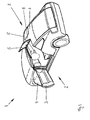
- a two-door motor vehicle 1 is shown schematically. Both on the Driver and on the passenger side of the motor vehicle 1 is ever a roof door 2 provided.
- the roof door 2 on the driver's side is shown in the open state. It comprises a side door 3 with frameless side window 4 and a Roof wing 5.
- the side door 3 is in the direction of travel at the front of the vehicle body hinged.
- the roof wing 5 is about an approximately longitudinal direction of the motor vehicle. 1 lying axis folded up from the roof surface of the vehicle roof 7.
- the roof wing door the passenger side has a mirror-image construction. She is closed shown.
- Each roof wing 5 is over two hinges 6a and 6b swingably attached to the vehicle roof 7.
- each a locking device provided (not visible here), with the roof wing 5 of the hinges 6a and 6b is detachable.
- the roof wing 5 of the hinges 6a and 6b is detachable.
- the roof wing 5 for example carried in the trunk of the vehicle.
- the roof wing 5 at any time back to the hinges 6a and Fix 6b.
- the side doors 3 receive the occupants freedom to the side and up and a similar driving experience as in a convertible.
- a roof bar 8 is present in the parts of the Locking device and parts of a vibration drive for the two roof wings. 5 are arranged.
- the roof wings 5 can be folded down, closed state of the Remove vehicle roof 7.
- the construction is designed so that a release of the Locking device 5 is possible only in the closed position of the roof wing 5. This is an advantage of the proposed roof door 2, because almost no components the locking device when operating a roof wing 5 with swinging up and down have to.
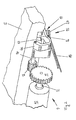
- Fig. 2 the roof wing 5 is shown in Fig. 1 fragmentary. It is the Rear of the hinge 6a shown, with which the roof spoiler 5 on the vehicle roof 7 is articulated. In the illustrated position of the hinge 6a, the roof wing 5 folded down and closed the vehicle roof 7.
- the illustrated mechanical Components are located in the region of the roof bar 8 of the vehicle roof 7 recognize is a vibratory drive 9, with the hinge 6a is opened and closed.
- the hinge 6b may also be provided with a vibratory drive.
- the Oscillating drive 9 essentially has a drive motor 10 with a drive pinion 11 on a motor shaft 12 of the drive motor 10 and an output pinion 13 on a drive shaft 14 for the hinge 6a.
- the output pinion 13 with small Diameter is rotatably received at a shaft end of the drive shaft 14.
- the hinge 6a is rotationally fixed at the opposite end of the drive shaft 14 appropriate.
- the pinions 11 and 13 cause a translation in the fast, since the drive pinion 11 on the motor shaft 12 a larger Diameter than the output pinion 13, with the hinge 6 a on a Wave is arranged.
- a locking device 15 For releasable connection between the roof wing 5 and hinge 6a is a locking device 15 provided with an automatic closure.
- the locking device 15 or the automatic closure has a locking element 16.
- the locking element 16 is arranged in a receiving opening 17 of the roof wing 5.
- the locking element 16 For actuating the locking element 16, for example, in order to release the Connection between the roof wing 5 and hinge 6 a, the locking element 16 must to be turned around. A rotation of the locking element 16 is only in closed Ste I-ment the roof wing 5 is provided. In this way it is spared components of the To install locking device 15 in the roof wing 5, the mass during a swinging movement of the roof wing 5 would always be moved with.
- the pull strap 18 is at a Disengaged coupling part, which is explained below with reference to FIG. 3 in more detail.
- the coupling part is located directly in the vicinity of the hinge 6a, namely the locking member 16 opposite. The hinge 6a is thus between the locking element 16 and the coupling part.
- Fig. 3 shows the roof wing 5 of FIG. 2 from a different perspective and in the folded up. In this perspective, the front of the hinge 6a to see. The locking member 16 in the roof wing 5 is not in this perspective visible, noticeable.
- a coupling device 19 will be explained with reference to FIG Part of the locking device 15 and the automatic closure is.
- the Coupling device 19 has two coupling parts, namely the above-mentioned Coupling part with pull strap 18 and a second coupling part, with the locking element 16 is firmly connected and according to FIG. 3 on the locking member 16th remote side protrudes from the hinge 6a out.
- the coupling part with pull strap 18 is formed as a rotary adapter 20 and relative to the vehicle roof. 7 stationary arranged.
- the provided on the hinge 6 a coupling part is as Drive piece 21 formed on the locking member 16 and in the hinge rotatably mounted.
- the driving piece can be closed by a roof wing 5 Oscillation movement in the direction of the dashed arrow X in the rotary adapter Engage 20.
- the engaged position is best in the enlarged view visible according to FIG. 4.
- FIG. 2 also shows the engaged position, wherein in Fig. 2, only the rotary adapter 20 is visible, but the engaged Drive piece 21 is covered.
- the driving piece 21 fits as shown in FIG. 4 in the folded down State of the hinge 6a form fit into the rotary adapter 20 into it.
- the locking member 16 To release the roof wing 5 of the hinge 6a or fixing the Roof wing 5 on the hinge 6a, the locking member 16 must be rotated.
- the rotary movement is via the rotary drive with the pull belt 18, the rotary adapter 20 and the driving piece 21 initiated.
- the pull strap 18 is in the figures 2, 3, and 4 shown.
- a drive device would with large space requirements hinder the headroom of the vehicle occupants. For this reason, the drive for the rotary adapter 20 to another Shifted position in the vehicle roof 7 and is using the tension belt 18 to save space transferred to the rotary adapter 20.
- the pull strap 18 For the purpose of actuation of the locking element 16 the pull strap 18 is set in motion and the rotary adapter 20 is rotated.
- Rotary adapter 20 rotates the driving piece 21 and thus the locking member 16th
- the locking member 16 By the movement of the locking member 16 in a rotational direction of the Dachfl is 5 detached from the hinge 6a and by a movement of the locking element 16 in the opposite direction of rotation of the roof wing 5 is at the hinge 6a fixed.
- FIG. 4 An alternative embodiment of a roof door is shown in FIG. Of the Structure and function correspond to the embodiment, with reference to the figures 2, 3 and Fig. 4 has been explained. For identical components, the same reference numerals are given, as in Fig. 4.
- the locking device 15 is in addition to the automatic closure provided with a hand closure 22.
- the automatic closure points a rotary drive with pull strap 18 for a rotary adapter 20.
- the rotary adapter 20 may optionally regardless of the additional hand lock 22 be operated directly.
Landscapes
- Engineering & Computer Science (AREA)
- Mechanical Engineering (AREA)
- Lock And Its Accessories (AREA)
- Power-Operated Mechanisms For Wings (AREA)
Abstract
Description
- Fig. 1
- ein Kraftfahrzeug mit Dachflügeltüren auf Fahrer- sowie Beifahrerseite; die Dachflügeltür der Fahrerseite in geöffnetem Zustand,
- Fig. 2
- eine schematische Darstellung mit einem Ausschnitt eines Dachflügels sowie einem Schwingantrieb und einer Arretiervorrichtung mit schaltbarem Automatikverschluss,
- Fig. 3
- eine ausschnittsweise Darstellung eines Dachflügels im geöffneten Zustand mit hochgeklapptem Scharnier sowie Schwingantrieb und Arretiervorrichtung mit Automatikverschluss,
- Fig. 4
- eine Detailansicht einer Kupplungseinrichtung des Automatikverschlusses der Arretiervorrichtung,
- Fig. 5
- eine Detailansicht auf eine alternative Ausführungsform einer Drehflügeltür mit Automatikverschluss und zusätzlichem Handverschluss.
- 1
- Kraftfahrzeug
- 2
- Dachflügeltür
- 3
- Seitentür
- 4
- Seitenscheibe
- 5
- Dachflügel
- 6a
- Scharnier
- 6b
- Scharnier
- 7
- Fahrzeugdach
- 8
- Dachsteg
- 9
- Schwingantrieb
- 10
- Antriebsmotor
- 11
- Antriebsritzel
- 12
- Motorwelle
- 13
- Abtriebsritzel
- 14
- Antriebswelle
- 15
- Arretiervorrichtung
- 16
- Arretierelement
- 17
- Aufnahmeöffnung
- 18
- Zugriemen
- 19
- Kupplungseinrichtung
- 20
- Drehadapter
- 21
- Mitnahmestück
- 22
- Handverschluss
- X
- Pfeil
Claims (19)
- Dachflügeltür (2) für ein Kraftfahrzeug (1), umfassend zwei Türelemente, nämlich eine Seitentür (3) sowie einen daran angrenzenden aufschwingbaren Dachflügel (5), der in einem Fahrzeugdach (7) angeordnet ist, wobei wenigstens ein Scharnier (6a, 6b) vorgesehen ist, über das der Dachflügel (5) schwingbar an dem Fahrzeugdach (7) angebracht ist,
dadurch gekennzeichnet, dass
eine Arretiervorrichtung (15) vorgesehen ist, mit der der Dachflügel (5) lösbar an dem Scharnier (6a, 6b) angebracht ist. - Dachflügeltür nach Anspruch 1,
dadurch gekennzeichnet, dass
die Arretiervorrichtung (15) einen unmittelbar an dem Dachflügel (5) vorgesehenen Handverschluss (22) zum Lösen und Fixieren der Verbindung zwischen Scharnier (6a, 6b) und Dachflügel (5) aufweist. - Dachflügeltür nach Anspruch 1 oder 2,
dadurch gekennzeichnet, dass
die Arretiervorrichtung (15) einen schaltbaren Automatikverschluss zum Lösen und Fixieren der Verbindung zwischen Scharnier (6a, 6b) und Dachflügel (5) aufweist. - Dachflügeltür nach Anspruch 3,
dadurch gekennzeichnet, dass
der Automatikverschluss ein Arretierelement (16) sowie eine Antriebseinrichtung für das Arretierelement (16) aufweist, wobei das Arretierelement (16) und die Antriebseinrichtung im geöffneten Zustand des Dachflügels (5) voneinander gelöst sind. - Dachflügeltür nach Anspruch 4,
dadurch gekennzeichnet, dass
das Arretierelement sowohl im montierten Zustand als auch im gelösten Zustand des Dachflügels (5) an dem Scharnier (6a, 6b) angeordnet und mit diesem schwingbar ist. - Dachflügeltür nach einem der Ansprüche 3 bis 5,
dadurch gekennzeichnet, dass
das Arretierelement (16) des Automatikverschlusses durch eine Drehbewegung betätigbar ist. - Dachflügeltür nach einem der Ansprüche 4 bis 6,
dadurch gekennzeichnet, dass
der Automatikverschluss eine Kupplungseinrichtung (19) aufweist, über die das Arretierelement (16) mit der Antriebseinrichtung kuppelbar ist. - Dachflügeltür nach Anspruch 7,
dadurch gekennzeichnet, dass
die Kupplungseinrichtung (19) zwei Kupplungsteile aufweist, die aufeinander zu- und voneinander wegbewegbar sind, wobei die Kupplungsteile durch eine Bewegung aufeinander zu einkuppelbar sind. - Dachflügeltür nach Anspruch 8,
dadurch gekennzeichnet, dass
ein Kupplungsteil als Drehadapter (20) und das zweite Kupplungsteil als Mitnahmestück (21) ausgebildet ist, wobei der Drehadapter (20) relativ zum Fah r-zeugdach (7) stationär angeordnet ist und das Mitnahmestück (21) drehfest an dem Arretierelement (16) angeordnet und mit diesem schwingbar ist. - Dachflügeltür nach Anspruch 9,
dadurch gekennzeichnet, dass
der Drehadapter (20) und das Mitnahmestück (21) durch Öffnen und Schließen des Dachflügels (5) ein- und auskuppelbar sind, wobei die Kupplungseinrichtung (19) im geschlossenen Zustand des Dachflügels (5) eingekuppelt und im geöffneten Zustand des Dachflügels (5) ausgekuppelt ist. - Dachflügeltür nach einem der Ansprüche 8 bis 10,
dadurch gekennzeichnet, dass
der Drehadapter (20) und das Mitnahmestück (21) der Kupplungseinrichtung (19) formschlüssig zusammenwirken. - Dachflügeltür nach einem der Ansprüche 8 bis 11,
dadurch gekennzeichnet, dass
der Drehadapter (20) mit einem Drehantrieb versehen ist. - Dachflügeltür nach Anspruch 12,
dadurch gekennzeichnet, dass
der Drehantrieb ein Zugmittel (18) aufweist. - Dachflügeltür nach einem der Ansprüche 1 bis 13,
dadurch gekennzeichnet, dass
ein Schwingantrieb (9) für den Dachflügel (5) vorgesehen ist. - Dachflügeltür nach Anspruch 14,
dadurch gekennzeichnet, dass
der Schwingantrieb (9) außerhalb des Dachflügels (5) in dem Fahrzeugdach (7) angeordnet ist. - Dachflügeltür nach Anspruch 14 oder 15,
dadurch gekennzeichnet, dass
der Schwingantrieb (9) als elektromechanischer Schwingantrieb ausgebildet ist. - Dachflügeltür nach einem der Ansprüche 14 bis 16,
dadurch gekennzeichnet, dass
der Schwingantrieb (9) an das Scharnier (6a, 6b) gekoppelt ist. - Dachflügeltür nach einem der Ansprüche 1 bis 17,
dadurch gekennzeichnet, dass
die Seitentür (3) als rahmenlose Tür ausgebildet ist. - Dachflügeltür nach einem der vorherigen Ansprüche,
dadurch gekennzeichnet, dass
der Dachflügel (5) automatisch mittels der Arretiervorrichtung (15) am Scharnier (6a, 6b) arretiert wird, nachdem er sich eine vorgegebene Zeit in der dafür vorgesehenen Position befindet.
Priority Applications (2)
| Application Number | Priority Date | Filing Date | Title |
|---|---|---|---|
| DE50309847T DE50309847D1 (de) | 2003-08-19 | 2003-08-19 | Dachflügeltür |
| EP03102595A EP1508463B1 (de) | 2003-08-19 | 2003-08-19 | Dachflügeltür |
Applications Claiming Priority (1)
| Application Number | Priority Date | Filing Date | Title |
|---|---|---|---|
| EP03102595A EP1508463B1 (de) | 2003-08-19 | 2003-08-19 | Dachflügeltür |
Publications (2)
| Publication Number | Publication Date |
|---|---|
| EP1508463A1 true EP1508463A1 (de) | 2005-02-23 |
| EP1508463B1 EP1508463B1 (de) | 2008-05-14 |
Family
ID=34042973
Family Applications (1)
| Application Number | Title | Priority Date | Filing Date |
|---|---|---|---|
| EP03102595A Expired - Lifetime EP1508463B1 (de) | 2003-08-19 | 2003-08-19 | Dachflügeltür |
Country Status (2)
| Country | Link |
|---|---|
| EP (1) | EP1508463B1 (de) |
| DE (1) | DE50309847D1 (de) |
Cited By (6)
| Publication number | Priority date | Publication date | Assignee | Title |
|---|---|---|---|---|
| CN103255969A (zh) * | 2013-02-22 | 2013-08-21 | 浙江吉利汽车研究院有限公司杭州分公司 | 车门铰链机构及通过该机构开关车门的方法 |
| CN105751864A (zh) * | 2016-02-29 | 2016-07-13 | 北京汽车研究总院有限公司 | 一种车门总成及汽车 |
| DE102004014692B4 (de) * | 2004-03-25 | 2020-03-19 | Volkswagen Ag | Fahrzeug |
| KR20220079206A (ko) * | 2020-12-04 | 2022-06-13 | 현대자동차주식회사 | 차량의 2단 오픈 크로스 바 프레임 구조 |
| CN114729556A (zh) * | 2019-11-25 | 2022-07-08 | 纬湃技术有限公司 | 用于机动车侧门的执行器 |
| US20230311724A1 (en) * | 2022-04-05 | 2023-10-05 | GM Global Technology Operations LLC | Vehicle having a folding mid-gate with an integrated seat |
Citations (5)
| Publication number | Priority date | Publication date | Assignee | Title |
|---|---|---|---|---|
| US2857198A (en) | 1956-01-18 | 1958-10-21 | Gen Motors Corp | Door actuated roof closure for vehicle side door opening |
| US3622197A (en) * | 1969-09-25 | 1971-11-23 | Gen Motors Corp | Vehicle body closure |
| JPS61175119A (ja) * | 1985-01-30 | 1986-08-06 | Yukio Kawakami | 自動車 |
| JPS6291316A (ja) * | 1985-10-18 | 1987-04-25 | Mazda Motor Corp | 自動車のドア構造 |
| US20020079719A1 (en) * | 2000-10-16 | 2002-06-27 | Steven Crijns | Vehicle having a removable rigid roof |
-
2003
- 2003-08-19 EP EP03102595A patent/EP1508463B1/de not_active Expired - Lifetime
- 2003-08-19 DE DE50309847T patent/DE50309847D1/de not_active Expired - Lifetime
Patent Citations (5)
| Publication number | Priority date | Publication date | Assignee | Title |
|---|---|---|---|---|
| US2857198A (en) | 1956-01-18 | 1958-10-21 | Gen Motors Corp | Door actuated roof closure for vehicle side door opening |
| US3622197A (en) * | 1969-09-25 | 1971-11-23 | Gen Motors Corp | Vehicle body closure |
| JPS61175119A (ja) * | 1985-01-30 | 1986-08-06 | Yukio Kawakami | 自動車 |
| JPS6291316A (ja) * | 1985-10-18 | 1987-04-25 | Mazda Motor Corp | 自動車のドア構造 |
| US20020079719A1 (en) * | 2000-10-16 | 2002-06-27 | Steven Crijns | Vehicle having a removable rigid roof |
Non-Patent Citations (2)
| Title |
|---|
| PATENT ABSTRACTS OF JAPAN vol. 010, no. 385 (M - 548) 24 December 1986 (1986-12-24) * |
| PATENT ABSTRACTS OF JAPAN vol. 011, no. 301 (M - 628) 30 September 1987 (1987-09-30) * |
Cited By (11)
| Publication number | Priority date | Publication date | Assignee | Title |
|---|---|---|---|---|
| DE102004014692B4 (de) * | 2004-03-25 | 2020-03-19 | Volkswagen Ag | Fahrzeug |
| CN103255969A (zh) * | 2013-02-22 | 2013-08-21 | 浙江吉利汽车研究院有限公司杭州分公司 | 车门铰链机构及通过该机构开关车门的方法 |
| CN103255969B (zh) * | 2013-02-22 | 2015-05-13 | 浙江吉利汽车研究院有限公司杭州分公司 | 车门铰链机构及通过该机构开关车门的方法 |
| CN105751864A (zh) * | 2016-02-29 | 2016-07-13 | 北京汽车研究总院有限公司 | 一种车门总成及汽车 |
| CN114729556A (zh) * | 2019-11-25 | 2022-07-08 | 纬湃技术有限公司 | 用于机动车侧门的执行器 |
| KR20220079206A (ko) * | 2020-12-04 | 2022-06-13 | 현대자동차주식회사 | 차량의 2단 오픈 크로스 바 프레임 구조 |
| KR102829872B1 (ko) | 2020-12-04 | 2025-07-03 | 현대자동차주식회사 | 차량의 2단 오픈 크로스 바 프레임 구조 |
| US20230311724A1 (en) * | 2022-04-05 | 2023-10-05 | GM Global Technology Operations LLC | Vehicle having a folding mid-gate with an integrated seat |
| CN116923211A (zh) * | 2022-04-05 | 2023-10-24 | 通用汽车环球科技运作有限责任公司 | 具有带有一体式座椅的折叠式中间门的车辆 |
| US11999274B2 (en) * | 2022-04-05 | 2024-06-04 | GM Global Technology Operations LLC | Vehicle having a folding mid-gate with an integrated seat |
| DE102022127369B4 (de) * | 2022-04-05 | 2025-05-22 | GM Global Technology Operations LLC | Fahrzeug mit einem klappbaren Mid-Gate mit integriertem Sitz |
Also Published As
| Publication number | Publication date |
|---|---|
| DE50309847D1 (de) | 2008-06-26 |
| EP1508463B1 (de) | 2008-05-14 |
Similar Documents
| Publication | Publication Date | Title |
|---|---|---|
| EP1997997B1 (de) | Verfahren zur motorischen Verstellung einer Kraftfahrzeugtür | |
| DE3413379C2 (de) | Verriegelungsvorrichtung für ein Verdeck am Windschutzscheibenrahmen eines Kraftfahrzeuges | |
| DE19721229B4 (de) | Verschluß für ein Verdeck eines Fahrzeuges, insbesondere eines Personenkraftwagens | |
| EP0778386B1 (de) | Betätigungseinrichtung zum Entriegeln wenigstens eines schwenkbaren Deckels eines Fahrzeuges, insbesondere Kraftfahrzeuges | |
| DE68910038T2 (de) | Flexibler Verdeckmechanismus eines Fahrzeuges. | |
| EP1245419B1 (de) | Cabriolet-Fahrzeug mit einem Windschott | |
| DE10243898B4 (de) | Türanordnung bei einer Kraftfahrzeugkarosserie | |
| DE10313496B4 (de) | Verdeck eines Kraftfahrzeugs | |
| EP0826537A1 (de) | Dachkonstruktion für ein Kraftfahrzeug, insbesondere für einen Personenkraftwagen | |
| DE602004000026T2 (de) | Vorrichtung für ein öffnungsfähiges Fahrzeugsdach | |
| DE19604855B4 (de) | Verdeck für Personenkraftwagen mit Fließheck | |
| DE19811481A1 (de) | Versenkbares Festdach für Cabrio-Fahrzeuge | |
| DE3835018A1 (de) | Fahrzeugdach | |
| EP1088142B1 (de) | Vorrichtung zum verbinden eines aussengriffs mit einem schliesssystem | |
| EP1508463B1 (de) | Dachflügeltür | |
| EP1243454B1 (de) | Verstellbares Hardtop-Cabrioletfahrzeugdach aus zwei entlang der Fahrzeuglängsachse geteilten Dachteilen | |
| DE3908239C1 (de) | ||
| EP0529288A1 (de) | Dachanordnung für ein Kraftfahrzeug | |
| DE4141820A1 (de) | Verstellvorrichtung fuer ein schwenkteil an einem fahrzeug | |
| DE60112070T2 (de) | An der dachverkleidung angebrachtes antriebssystem für eine fahrzeugheckklappe | |
| EP1108846B1 (de) | Schwenktürantrieb | |
| DE102004043220A1 (de) | Kombinierte Schließeinrichtung | |
| DE202019100744U1 (de) | Kippantriebsvorrichtung für einen Flügel | |
| DE102006042197A1 (de) | Gestängeanordnung für einen Verdeckkastendeckel eines Cabriolet-Fahrzeuges | |
| DE102004055404A1 (de) | Fahrzeugdach |
Legal Events
| Date | Code | Title | Description |
|---|---|---|---|
| PUAI | Public reference made under article 153(3) epc to a published international application that has entered the european phase |
Free format text: ORIGINAL CODE: 0009012 |
|
| AK | Designated contracting states |
Kind code of ref document: A1 Designated state(s): AT BE BG CH CY CZ DE DK EE ES FI FR GB GR HU IE IT LI LU MC NL PT RO SE SI SK TR |
|
| AX | Request for extension of the european patent |
Extension state: AL LT LV MK |
|
| 17P | Request for examination filed |
Effective date: 20050823 |
|
| AKX | Designation fees paid |
Designated state(s): DE FR GB |
|
| 17Q | First examination report despatched |
Effective date: 20070625 |
|
| GRAP | Despatch of communication of intention to grant a patent |
Free format text: ORIGINAL CODE: EPIDOSNIGR1 |
|
| GRAS | Grant fee paid |
Free format text: ORIGINAL CODE: EPIDOSNIGR3 |
|
| GRAA | (expected) grant |
Free format text: ORIGINAL CODE: 0009210 |
|
| AK | Designated contracting states |
Kind code of ref document: B1 Designated state(s): DE FR GB |
|
| REG | Reference to a national code |
Ref country code: GB Ref legal event code: FG4D Free format text: NOT ENGLISH |
|
| REF | Corresponds to: |
Ref document number: 50309847 Country of ref document: DE Date of ref document: 20080626 Kind code of ref document: P |
|
| PLBE | No opposition filed within time limit |
Free format text: ORIGINAL CODE: 0009261 |
|
| STAA | Information on the status of an ep patent application or granted ep patent |
Free format text: STATUS: NO OPPOSITION FILED WITHIN TIME LIMIT |
|
| 26N | No opposition filed |
Effective date: 20090217 |
|
| PGFP | Annual fee paid to national office [announced via postgrant information from national office to epo] |
Ref country code: FR Payment date: 20090806 Year of fee payment: 7 |
|
| PGFP | Annual fee paid to national office [announced via postgrant information from national office to epo] |
Ref country code: DE Payment date: 20090831 Year of fee payment: 7 Ref country code: GB Payment date: 20090708 Year of fee payment: 7 |
|
| GBPC | Gb: european patent ceased through non-payment of renewal fee |
Effective date: 20100819 |
|
| REG | Reference to a national code |
Ref country code: FR Ref legal event code: ST Effective date: 20110502 |
|
| REG | Reference to a national code |
Ref country code: DE Ref legal event code: R119 Ref document number: 50309847 Country of ref document: DE Effective date: 20110301 |
|
| PG25 | Lapsed in a contracting state [announced via postgrant information from national office to epo] |
Ref country code: FR Free format text: LAPSE BECAUSE OF NON-PAYMENT OF DUE FEES Effective date: 20100831 Ref country code: DE Free format text: LAPSE BECAUSE OF NON-PAYMENT OF DUE FEES Effective date: 20110301 |
|
| PG25 | Lapsed in a contracting state [announced via postgrant information from national office to epo] |
Ref country code: GB Free format text: LAPSE BECAUSE OF NON-PAYMENT OF DUE FEES Effective date: 20100819 |