EP1507629B1 - Syst me dot d'un raccordement d'outil - Google Patents
Syst me dot d'un raccordement d'outil Download PDFInfo
- Publication number
- EP1507629B1 EP1507629B1 EP03727169A EP03727169A EP1507629B1 EP 1507629 B1 EP1507629 B1 EP 1507629B1 EP 03727169 A EP03727169 A EP 03727169A EP 03727169 A EP03727169 A EP 03727169A EP 1507629 B1 EP1507629 B1 EP 1507629B1
- Authority
- EP
- European Patent Office
- Prior art keywords
- insertion tool
- tool
- toolholding
- fixture
- insert tool
- Prior art date
- Legal status (The legal status is an assumption and is not a legal conclusion. Google has not performed a legal analysis and makes no representation as to the accuracy of the status listed.)
- Expired - Lifetime
Links
- 230000037431 insertion Effects 0.000 claims description 14
- 238000003780 insertion Methods 0.000 claims description 14
- 239000002184 metal Substances 0.000 description 35
- 210000002105 tongue Anatomy 0.000 description 4
- 230000006378 damage Effects 0.000 description 3
- 238000009434 installation Methods 0.000 description 3
- 230000005540 biological transmission Effects 0.000 description 2
- 230000015572 biosynthetic process Effects 0.000 description 2
- 238000005452 bending Methods 0.000 description 1
- 230000000994 depressogenic effect Effects 0.000 description 1
- 238000005553 drilling Methods 0.000 description 1
- 230000005484 gravity Effects 0.000 description 1
- 239000000463 material Substances 0.000 description 1
Images


Classifications
-
- B—PERFORMING OPERATIONS; TRANSPORTING
- B24—GRINDING; POLISHING
- B24B—MACHINES, DEVICES, OR PROCESSES FOR GRINDING OR POLISHING; DRESSING OR CONDITIONING OF ABRADING SURFACES; FEEDING OF GRINDING, POLISHING, OR LAPPING AGENTS
- B24B23/00—Portable grinding machines, e.g. hand-guided; Accessories therefor
- B24B23/02—Portable grinding machines, e.g. hand-guided; Accessories therefor with rotating grinding tools; Accessories therefor
-
- B—PERFORMING OPERATIONS; TRANSPORTING
- B24—GRINDING; POLISHING
- B24B—MACHINES, DEVICES, OR PROCESSES FOR GRINDING OR POLISHING; DRESSING OR CONDITIONING OF ABRADING SURFACES; FEEDING OF GRINDING, POLISHING, OR LAPPING AGENTS
- B24B45/00—Means for securing grinding wheels on rotary arbors
-
- B—PERFORMING OPERATIONS; TRANSPORTING
- B24—GRINDING; POLISHING
- B24D—TOOLS FOR GRINDING, BUFFING OR SHARPENING
- B24D7/00—Bonded abrasive wheels, or wheels with inserted abrasive blocks, designed for acting otherwise than only by their periphery, e.g. by the front face; Bushings or mountings therefor
- B24D7/16—Bushings; Mountings
Definitions
- the invention is based on a system with a tool holder according to the preamble of claim 1, (see, for example WO-A-01 960 067 ).
- a system with a grinder tool holder for a hand-held angle grinder and a grinding wheel is known.
- the angle grinder has a drive shaft which has a thread on the tool side.
- the grinding machine tool holder has a driver and a clamping nut. To mount the grinding wheel of the driver is pushed with a mounting hole on a collar of the drive shaft and clamped over the clamping nut frictionally against a bearing surface of the drive shaft.
- the driver has a tool side in the axial direction extending collar radially on two opposite Has sides on its outer circumference recesses which extend in the axial direction to a bottom of the collar. Starting from the recesses extending against the drive direction of the drive shaft in each case a groove on the outer circumference of the collar. The grooves are closed against the drive direction of the drive shaft and taper axially from the recesses against the drive direction of the drive shaft.
- the grinding wheel has a hub with a mounting opening in which two opposite, radially inwardly pointing tongues are arranged.
- the tongues can be introduced into the recesses in the axial direction and then into the grooves in the circumferential direction, counter to the drive direction.
- the grinding wheel is positively connected via the tongues in the grooves in the axial direction and frictionally fixed by the tapered contour of the grooves. During operation, the adhesion increases due to acting on the grinding wheel reaction forces acting counter to the drive direction.
- a stopper is arranged in the region of a recess on the circumference of the collar and is movably mounted in an opening in the axial direction. In a working position pointing downwards with the grinding wheel, the stopper is deflected by gravity axially in the direction of the grinding wheel, closes the groove in the direction of the recess and blocks movement of the tongue located in the groove in the drive direction of the drive shaft.
- the invention relates to a system having the features of claim 1.
- the invention relates to a system with a tool holder, which has a driving device, via which an insert tool with a drive shaft is operatively connected, and with an insert tool which is operatively connected via at least one movable against a spring element latching element with the driving device, the engages in an operating position of the insert tool and the insert tool fixed in a form-fitting manner.
- the tool holder and the insert tool have at least two matched, corresponding form elements for simplifying a mounting of the insert tool. It is an advantageous and easy installation of the insert tool achievable, and in particular by the form elements form a guide, so that clamping hooks of the driving device can automatically engage in corresponding recesses of the hub.
- the corresponding form elements are matched with respect to the dimensioning of the insert tool, whereby in particular a correct assignment of a diameter of the insert tool to a rotational speed of the power tool can be ensured and damage can be avoided.
- a correct assignment of a diameter of the insert tool to a rotational speed of the power tool can be ensured and damage can be avoided.
- other dimensions than encoding criterion are conceivable, in particular a strength of the insert tool.
- the mold element arranged on the tool holder is formed by a projection arranged on a collar of the tool holder, extending in the radial direction, and the mold element arranged on the mold element is formed by a recess.
- a radially inwardly extending projection and the tool holder a recess is formed on the hub or on the insert tool.
- the projection in the axial direction has a distance from a contact surface.
- the insert tool can be rotated to reach a locking position under the projection become.
- the projection represents an additional safeguard of the insert tool and provides an additional contribution to safety for the operator.
- At least three uniformly distributed over the circumference projections are arranged on the tool holder.
- the three projections span an unambiguous certain level and form with their end faces an advantageous contact surface for the insert tool.
- the Einsatstechnikzeug can simply be placed on the bearing surface and rotated during assembly in the tool holder until the mold elements are in a mutually corresponding position.
- the finding and threading of the retaining hooks in the corresponding recesses in the hub is thereby significantly facilitated and jamming and tilting of the insertion tool during assembly can be advantageously avoided.
- the projection may be integrally formed on a separate component or advantageously designed in one piece with the tool holder, in the latter case additional components, assembly costs and costs can be saved.
- a cylindrical part of the collar projects in the axial direction over end faces of the form elements.
- the insert tool can be structurally simply centered and rotated during assembly in the tool holder.
- Fig. 1 shows an angle grinder 32 from above with a mounted in a housing 34, not shown electric motor.
- the angle grinder 32 can be guided via a first, in the housing 34 on a side facing away from an insert tool 14, extending in the longitudinal direction handle 36 and a second attached to a transmission housing 38 in the field of insert tool 14, transversely to the longitudinal direction extending handle 40.
- a drive shaft 16 can be driven, at whose end facing the insertion tool 14 a tool holder with a driving device 12 is arranged ( Fig. 2 ).
- the tool holder and the insert tool 14 form a system.
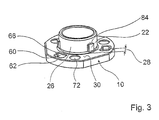
- the tool holder has a driving flange 10, which forms a contact surface 30 for the insertion tool 14 ( Fig. 2 and Fig. 3 ).
- a collar 26 is integrally formed on a side facing the insert tool 14, over which the insert tool 14 is radially centered with its center hole 46 in the mounted state.
- three mold elements 22 are arranged, which are formed by radially outwardly extending projections.
- the integrally formed with the collar 26 form elements 22 are distributed uniformly over an outer circumference of the collar 26 and have in the axial direction 54, 64 a distance 28 to the contact surface 30. With its end facing the insert tool 14, the collar 26 projects beyond the shaped elements 22 in the axial direction 54.
- a metal plate 48 On a side facing away from the insert tool 14 of the driving flange 10 is a metal plate 48 with three circumferentially 50, 52 evenly distributed, integrally formed, extending in the axial direction 54 clamping hooks 56 for axially fixing the insert tool 14 is arranged.
- the clamping hooks 56 are formed in a bending operation on the metal plate 48.
- the driving flange 10 When mounting the driving device 12, the driving flange 10, a spring element 58 and the metal plate 48 is pre-assembled.
- the spring element 58 is not closer to one shown collar of the driving flange 10 is pushed, which points in the direction away from the insert tool 14 direction.
- the clamping hooks 56 of the sheet metal plate 48 which at its free end have a hook-shaped extension with an obliquely pointing in the circumferential direction 52 94, guided in the axial direction 54 through recesses 60 of the driving flange 10, respectively by common areas 62 of the recesses 60 (FIGS. Fig. 2 and 3 ).
- the spring element 58 By compressing and twisting the metal plate 48 and the driving flange 10 against each other, the spring element 58 is biased and the metal plate 48 and the driving flange 10 are positively connected in the axial direction 54, 64, namely by the hook-shaped projections in narrow portions 66 of the recesses 60 are rotated ( Fig. 2 and 3 ).
- the metal plate 48 is then, loaded by the spring element 58, supported on the contact surface 30 of the driving flange 10 via edges of the hook-shaped extensions which point axially in the direction away from the insert tool 14 direction.
- the spring element 58 and the driving flange 10 are pre-assembled, is formed by a coil spring spring member 18 and a drive plate 96 with three evenly distributed over the circumference, extending in the axial direction 54 bolt 20 on a Drive shaft 16 attached ( Fig. 2 ).
- the preassembled module consisting of the metal plate 48, the spring element 58 and the driving flange 10, is mounted on the drive shaft 16.
- the bolts 20 are in the assembly by the periphery of the metal plate 48th formed tabs 68, the holes 70, and guided by located in the driving flange 10 through holes 72 and engage in the assembled state through the through holes 72 therethrough.
- the metal plate 48 and the drive plate 96 are secured to each other via the bolts 20 against rotation.
- the tool holder is secured on the drive shaft 16 with a screw 74.
- the insertion tool 14 formed by a cutting disk has a sheet metal hub 42 formed by a separate component, which has three uniformly distributed, in the circumferential direction 50, 52, in the axial direction 54, cup-shaped recesses 76 whose diameter is slightly larger than the diameter of the bolt 20. Furthermore, the sheet metal hub 42 has three evenly distributed in the circumferential direction 50, 52, extending in the circumferential direction 50, 52 recesses 78, each having a narrow and a wide range 80, 82.
- the diameter of the center hole 46 of the sheet metal hub 42 is selected so that the insert tool 14 can be clamped with a conventional clamping system with a clamping flange and a spindle nut on a conventional angle grinder. It ensures a so-called backward compatibility.
- the sheet metal hub 42 of the insertion tool 14 has three mold elements 24 which are distributed in the circumferential direction 50, 52 uniformly over the circumference of the centering bore 46 ( Fig.2 ).
- the mold elements 24 are formed here by recesses.
- the mold elements 22 of the tool holder and the mold elements 24 of the insert tool 14 are matched, corresponding mold elements to simplify installation of the insert tool 14. Furthermore, the corresponding form elements 22, 24 form a coding means for avoiding assembly of an impermissible insert tool of the same kind Form elements 22, 24 coordinated with respect to a diameter of the insert tool 14, so that use tools for use in high speed machines have a wide shape element or a wide coding and insert tools for use in machines with low speed a narrow form element or a narrow encoding.
- the sheet metal hub 42 of the insert tool 14 is connected via a rivet connection firmly with an abrasive and pressed and is executed by a pointing in the axial direction 64 formation 44 cup-shaped.
- the insert tool 14 When mounting the insert tool 14, the insert tool 14 is pushed with its center hole 46 on the mold elements 22 in the axial direction 54 superior part of the collar 26 and pre-centered radially. The insert tool 14 comes here to contact surfaces 84 of the mold elements 22 to lie. Twisting the insert tool 14 in the circumferential direction 50, 52 brings the mold elements 22, 24 to cover. The insert tool 14 or the sheet metal hub 42 can then slide in the axial direction 64 in the direction of the contact surface 30, and the sheet metal hub 42 comes to rest on the bolt 20.
- a subsequent pressing of the sheet metal hub 42 to the contact surface 30 of the driving flange 10 causes the bolt 20 in the Through holes 72 and the drive plate 96 are axially displaced against the spring force of the spring element 18 on the drive shaft 16 in the direction away from the insert tool 14 64 direction.
- radially outwardly directed recesses 86 of the driver disk 96 engage in corresponding locking pockets 88 of a bearing flange 90 fixedly connected to the transmission housing 38 and lock the drive shaft 16.
- the sheet metal hub 42 can be rotated counter to a drive direction 98.
- the rotation of the sheet metal hub 42 causes the sheet metal hub 42 to slide with its edge of the centering bore 46 into the distance 28 between the mold elements 22 and the abutment surface 30 of the driving flange 10 and can be secured against falling down by the shaped elements 22 in the axial direction.
- the rotation of the sheet metal hub 42 causes the hook-shaped projections to be displaced into the arcuate, narrow regions 80 of the recesses 78 of the sheet metal hub 42.
- the metal plate 48 is moved with the clamping hooks 56 by not shown inclined surfaces axially against the pressure of the spring element 58 in the direction 54 until the contact surfaces of the hook-shaped projections in the arcuate, narrow areas 80 laterally come to rest next to the recesses 78 of the sheet metal hub 42.
- a release button 92 is pressed in the axial direction 64.
- the release button 92 pushes the drive plate 96 in the axial direction 64, and the recesses 86 of the drive plate 96 engage with the locking pockets 88 in engagement.
- the drive shaft 16 is locked.
- the bolts 20 are in this case with the recesses 76 of the sheet metal hub 42 disengaged, and the sheet metal hub 42 can be rotated in the circumferential direction 52 until the clamping hooks 56 can slide through the recesses 78.
- the mold elements 22, 24 in this case reach into a corresponding position, and the sheet metal hub 42 can be removed in the axial direction 54.
Claims (7)
- Système comprenant un porte-outil, qui présente un dispositif d'entraînement (12), par le biais duquel un outil inséré (14) peut être connecté fonctionnellement à un arbre d'entraînement (16), et comprenant un outil inséré (14) qui peut être connecté fonctionnellement au dispositif d'entraînement (12) par le biais d'au moins un élément d'encliquetage (20) monté de manière déplaçable axialement à l'encontre d'un élément de ressort (18), qui s'encliquète dans une position de fonctionnement de l'outil inséré (14) et qui fixe l'outil inséré (14) par engagement par correspondance géométrique, le porte-outil et l'outil inséré (14) présentant au moins deux éléments façonnés (22 ,24) correspondants, adaptés l'un à l'autre, pour faciliter un montage de l'outil inséré (14), caractérisé en ce que les éléments façonnés (22, 24) correspondants forment un moyen de codage pour éviter un montage d'un outil inséré non autorisé mais de type similaire.
- Système selon la revendication 1, caractérisé en ce que les éléments façonnés (22, 24) correspondants sont adaptés l'un à l'autre en termes de dimensionnement de l'outil inséré (14).
- Système selon l'une quelconque des revendications 1 et 2, caractérisé en ce que l'élément façonné (22) disposé sur le porte-outil est formé par une saillie disposée sur un épaulement (26) du porte-outil, s'étendant dans la direction radiale, et l'élément façonné (24) disposé sur l'outil inséré (14) est formé par un évidement.
- Système selon la revendication 3, caractérisé en ce que la saillie (22) présente dans la direction axiale un écartement (28) par rapport à une surface d'appui (30).
- Système selon la revendication 3 ou 4, caractérisé en ce qu'au moins trois saillies (22) réparties uniformément sur la périphérie sont disposées sur le porte-outil.
- Système selon l'une quelconque des revendications 3 à 5, caractérisé en ce que la saillie (22) est réalisée d'une seule pièce avec l'épaulement (26) du porte-outil.
- Système selon l'une quelconque des revendications 3 à 6, caractérisé en ce qu'une partie cylindrique de l'épaulement (26) dépasse dans la direction axiale au-delà de surfaces frontales (84) des éléments façonnés (22).
Applications Claiming Priority (3)
| Application Number | Priority Date | Filing Date | Title |
|---|---|---|---|
| DE10222292A DE10222292A1 (de) | 2002-05-18 | 2002-05-18 | System mit einer Werkzeugaufnahme |
| DE10222292 | 2002-05-18 | ||
| PCT/DE2003/001079 WO2003097299A1 (fr) | 2002-05-18 | 2003-04-02 | Système doté d'un raccordement d'outil |
Publications (2)
| Publication Number | Publication Date |
|---|---|
| EP1507629A1 EP1507629A1 (fr) | 2005-02-23 |
| EP1507629B1 true EP1507629B1 (fr) | 2009-09-16 |
Family
ID=29413960
Family Applications (1)
| Application Number | Title | Priority Date | Filing Date |
|---|---|---|---|
| EP03727169A Expired - Lifetime EP1507629B1 (fr) | 2002-05-18 | 2003-04-02 | Syst me dot d'un raccordement d'outil |
Country Status (6)
| Country | Link |
|---|---|
| US (1) | US8167689B2 (fr) |
| EP (1) | EP1507629B1 (fr) |
| JP (1) | JP4504182B2 (fr) |
| CN (1) | CN100563928C (fr) |
| DE (2) | DE10222292A1 (fr) |
| WO (1) | WO2003097299A1 (fr) |
Families Citing this family (19)
| Publication number | Priority date | Publication date | Assignee | Title |
|---|---|---|---|---|
| DE10352288A1 (de) | 2003-11-08 | 2005-06-09 | Robert Bosch Gmbh | Werkzeugaufnahmevorrichtung |
| DE10352291A1 (de) | 2003-11-08 | 2005-06-02 | Robert Bosch Gmbh | Werkzeugaufnahmevorrichtung für ein Einsatzwerkzeug mit einer zumindest im Wesentlichen scheibenförmigen Nabe |
| DE10360252A1 (de) * | 2003-12-20 | 2005-07-21 | Robert Bosch Gmbh | Werkzeugadapter |
| DE10360246A1 (de) | 2003-12-20 | 2005-07-28 | Robert Bosch Gmbh | Einsatzwerkzeug für eine Werkzeugmaschine |
| DE10360248A1 (de) | 2003-12-20 | 2005-07-28 | Robert Bosch Gmbh | Einsatzwerkzeug für einen Winkelschleifer |
| DE102004028529A1 (de) * | 2004-06-11 | 2006-01-26 | Robert Bosch Gmbh | Werkzeugaufnahmevorrichtung für ein Einsatzwerkzeug |
| US8925931B2 (en) | 2010-04-29 | 2015-01-06 | Black & Decker Inc. | Oscillating tool |
| US9186770B2 (en) | 2010-04-29 | 2015-11-17 | Black & Decker Inc. | Oscillating tool attachment feature |
| US9073195B2 (en) | 2010-04-29 | 2015-07-07 | Black & Decker Inc. | Universal accessory for oscillating power tool |
| US9149923B2 (en) | 2010-11-09 | 2015-10-06 | Black & Decker Inc. | Oscillating tools and accessories |
| DE102011075228A1 (de) * | 2011-05-04 | 2012-11-08 | Robert Bosch Gmbh | Werkzeugspannvorrichtung |
| US20120294466A1 (en) * | 2011-05-18 | 2012-11-22 | Stefan Kristo | Temporary anchor for a hearing prosthesis |
| CN102814796B (zh) * | 2011-06-09 | 2015-08-19 | 苏州宝时得电动工具有限公司 | 动力工具及应用于该动力工具的工作头和转接器 |
| USD832666S1 (en) | 2012-07-16 | 2018-11-06 | Black & Decker Inc. | Oscillating saw blade |
| DE202015106711U1 (de) | 2015-12-09 | 2017-03-10 | Kolthoff Gabrovo Eood | Werkzeug für Oberflächenfeinbearbeitungen |
| SE540067C2 (en) * | 2016-04-25 | 2018-03-13 | Soedra Skogsaegarna Ekonomisk Foerening | Circular saw mounting device |
| US10265778B2 (en) | 2017-01-16 | 2019-04-23 | Black & Decker Inc. | Accessories for oscillating power tools |
| USD814900S1 (en) | 2017-01-16 | 2018-04-10 | Black & Decker Inc. | Blade for oscillating power tools |
| DE102017218622A1 (de) * | 2017-04-12 | 2018-10-18 | Robert Bosch Gmbh | Schleifmittelvorrichtung, insbesondere Schleiftellervorrichtung oder Stütztellervorrichtung |
Family Cites Families (13)
| Publication number | Priority date | Publication date | Assignee | Title |
|---|---|---|---|---|
| US3270467A (en) * | 1963-07-01 | 1966-09-06 | Merit Products Inc | Abrasive device |
| US3623281A (en) * | 1969-06-16 | 1971-11-30 | Robert H Moffat | Mounting fixture |
| JPS5831954U (ja) * | 1981-08-21 | 1983-03-02 | 日本レヂボン株式会社 | 砥石装着装置 |
| JPS6014840U (ja) * | 1983-07-11 | 1985-01-31 | 三和研磨工業株式会社 | 砥石の取付構造 |
| US4657428A (en) * | 1985-09-10 | 1987-04-14 | Wiley Edward R | Quick change mechanism for circular saw blades and other spinning disc devices |
| US4730952A (en) * | 1986-08-04 | 1988-03-15 | Wiley Edward R | Quick change mechanism for circular saw blades |
| DE19504563A1 (de) * | 1995-02-11 | 1996-08-14 | Stihl Maschf Andreas | Spanneinrichtung zum axialen Festspannen eines scheibenförmigen Werkzeugs |
| JPH08309654A (ja) | 1995-05-16 | 1996-11-26 | Ryobi Ltd | サンディング工具 |
| JPH1199460A (ja) * | 1997-09-29 | 1999-04-13 | Yanase Kk | 回転研磨具 |
| DE10017457A1 (de) * | 2000-04-07 | 2001-10-11 | Bosch Gmbh Robert | Schleifmaschinenwerkzeugaufnahme |
| US6523214B1 (en) * | 2000-06-14 | 2003-02-25 | Richard A. Kaiser | Quick mount attachment for rotary finishing tool |
| DE20012746U1 (de) * | 2000-07-22 | 2000-09-28 | Braasch Gerd | Schleifwerkzeug |
| US6332836B1 (en) * | 2001-04-02 | 2001-12-25 | Ming-Xin Tseng | Grinding wheel assembly |
-
2002
- 2002-05-18 DE DE10222292A patent/DE10222292A1/de not_active Ceased
-
2003
- 2003-04-02 WO PCT/DE2003/001079 patent/WO2003097299A1/fr active Application Filing
- 2003-04-02 JP JP2004504679A patent/JP4504182B2/ja not_active Expired - Fee Related
- 2003-04-02 EP EP03727169A patent/EP1507629B1/fr not_active Expired - Lifetime
- 2003-04-02 DE DE50311920T patent/DE50311920D1/de not_active Expired - Lifetime
- 2003-04-02 CN CNB038113627A patent/CN100563928C/zh not_active Expired - Fee Related
- 2003-04-02 US US10/511,285 patent/US8167689B2/en not_active Expired - Fee Related
Also Published As
| Publication number | Publication date |
|---|---|
| CN1652899A (zh) | 2005-08-10 |
| US20110097978A1 (en) | 2011-04-28 |
| DE50311920D1 (de) | 2009-10-29 |
| JP2005525944A (ja) | 2005-09-02 |
| EP1507629A1 (fr) | 2005-02-23 |
| JP4504182B2 (ja) | 2010-07-14 |
| CN100563928C (zh) | 2009-12-02 |
| WO2003097299A1 (fr) | 2003-11-27 |
| DE10222292A1 (de) | 2003-12-04 |
| US8167689B2 (en) | 2012-05-01 |
Similar Documents
| Publication | Publication Date | Title |
|---|---|---|
| EP1507629B1 (fr) | Syst me dot d'un raccordement d'outil | |
| EP1414620B1 (fr) | Systeme muni d'un raccordement d'outil | |
| EP1274548B1 (fr) | Logement d'outil mecanique destine a une lame de scie circulaire | |
| EP3500411B1 (fr) | Dispositif outil pour une machine-outil portative | |
| EP1684944B1 (fr) | Dispositif de raccordement d'outil destine a un outil insert et pourvu d'un nabe au moins sensiblement en forme de disque | |
| EP1274541B1 (fr) | Raccord d'outil | |
| EP1274544B1 (fr) | Porte-outil de meuleuse | |
| EP1339528B1 (fr) | Outil a main comportant un capteur destine a l'emission de signaux lors du remplacement de l'outil a main | |
| EP1404490B1 (fr) | Outil amovible pour meuleuse | |
| EP3500401B1 (fr) | Machine-outil | |
| EP1274543A1 (fr) | Support d'outil de meuleuse | |
| EP1513651B1 (fr) | Outil d'insertion muni d'une unite de fixation | |
| DE10225583A1 (de) | Werkzeugaufnahme und Einsatzwerkzeug | |
| EP1684943B1 (fr) | Dispositif porte-outil |
Legal Events
| Date | Code | Title | Description |
|---|---|---|---|
| PUAI | Public reference made under article 153(3) epc to a published international application that has entered the european phase |
Free format text: ORIGINAL CODE: 0009012 |
|
| 17P | Request for examination filed |
Effective date: 20041220 |
|
| AK | Designated contracting states |
Kind code of ref document: A1 Designated state(s): AT BE BG CH CY CZ DE DK EE ES FI FR GB GR HU IE IT LI LU MC NL PT RO SE SI SK TR |
|
| AX | Request for extension of the european patent |
Extension state: AL LT LV MK |
|
| DAX | Request for extension of the european patent (deleted) | ||
| RBV | Designated contracting states (corrected) |
Designated state(s): CH DE FR GB LI |
|
| 17Q | First examination report despatched |
Effective date: 20070502 |
|
| GRAP | Despatch of communication of intention to grant a patent |
Free format text: ORIGINAL CODE: EPIDOSNIGR1 |
|
| GRAS | Grant fee paid |
Free format text: ORIGINAL CODE: EPIDOSNIGR3 |
|
| GRAA | (expected) grant |
Free format text: ORIGINAL CODE: 0009210 |
|
| AK | Designated contracting states |
Kind code of ref document: B1 Designated state(s): CH DE FR GB LI |
|
| REG | Reference to a national code |
Ref country code: GB Ref legal event code: FG4D Free format text: NOT ENGLISH |
|
| REG | Reference to a national code |
Ref country code: CH Ref legal event code: EP |
|
| REF | Corresponds to: |
Ref document number: 50311920 Country of ref document: DE Date of ref document: 20091029 Kind code of ref document: P |
|
| PLBE | No opposition filed within time limit |
Free format text: ORIGINAL CODE: 0009261 |
|
| STAA | Information on the status of an ep patent application or granted ep patent |
Free format text: STATUS: NO OPPOSITION FILED WITHIN TIME LIMIT |
|
| 26N | No opposition filed |
Effective date: 20100617 |
|
| REG | Reference to a national code |
Ref country code: CH Ref legal event code: PL |
|
| REG | Reference to a national code |
Ref country code: FR Ref legal event code: ST Effective date: 20101230 |
|
| PG25 | Lapsed in a contracting state [announced via postgrant information from national office to epo] |
Ref country code: LI Free format text: LAPSE BECAUSE OF NON-PAYMENT OF DUE FEES Effective date: 20100430 Ref country code: CH Free format text: LAPSE BECAUSE OF NON-PAYMENT OF DUE FEES Effective date: 20100430 |
|
| PG25 | Lapsed in a contracting state [announced via postgrant information from national office to epo] |
Ref country code: FR Free format text: LAPSE BECAUSE OF NON-PAYMENT OF DUE FEES Effective date: 20100430 |
|
| PGFP | Annual fee paid to national office [announced via postgrant information from national office to epo] |
Ref country code: GB Payment date: 20170425 Year of fee payment: 15 |
|
| GBPC | Gb: european patent ceased through non-payment of renewal fee |
Effective date: 20180402 |
|
| PG25 | Lapsed in a contracting state [announced via postgrant information from national office to epo] |
Ref country code: GB Free format text: LAPSE BECAUSE OF NON-PAYMENT OF DUE FEES Effective date: 20180402 |
|
| PGFP | Annual fee paid to national office [announced via postgrant information from national office to epo] |
Ref country code: DE Payment date: 20210624 Year of fee payment: 19 |
|
| REG | Reference to a national code |
Ref country code: DE Ref legal event code: R119 Ref document number: 50311920 Country of ref document: DE |
|
| PG25 | Lapsed in a contracting state [announced via postgrant information from national office to epo] |
Ref country code: DE Free format text: LAPSE BECAUSE OF NON-PAYMENT OF DUE FEES Effective date: 20221103 |