EP1506833B1 - Connection de buse laser - Google Patents
Connection de buse laser Download PDFInfo
- Publication number
- EP1506833B1 EP1506833B1 EP03018178A EP03018178A EP1506833B1 EP 1506833 B1 EP1506833 B1 EP 1506833B1 EP 03018178 A EP03018178 A EP 03018178A EP 03018178 A EP03018178 A EP 03018178A EP 1506833 B1 EP1506833 B1 EP 1506833B1
- Authority
- EP
- European Patent Office
- Prior art keywords
- laser processing
- sliding piece
- nozzle
- processing nozzle
- laser
- Prior art date
- Legal status (The legal status is an assumption and is not a legal conclusion. Google has not performed a legal analysis and makes no representation as to the accuracy of the status listed.)
- Expired - Lifetime
Links
Images


Classifications
-
- B—PERFORMING OPERATIONS; TRANSPORTING
- B23—MACHINE TOOLS; METAL-WORKING NOT OTHERWISE PROVIDED FOR
- B23K—SOLDERING OR UNSOLDERING; WELDING; CLADDING OR PLATING BY SOLDERING OR WELDING; CUTTING BY APPLYING HEAT LOCALLY, e.g. FLAME CUTTING; WORKING BY LASER BEAM
- B23K26/00—Working by laser beam, e.g. welding, cutting or boring
- B23K26/14—Working by laser beam, e.g. welding, cutting or boring using a fluid stream, e.g. a jet of gas, in conjunction with the laser beam; Nozzles therefor
- B23K26/1462—Nozzles; Features related to nozzles
- B23K26/1482—Detachable nozzles, e.g. exchangeable or provided with breakaway lines
Definitions
- the invention relates to a laser processing apparatus having a laser processing head, a laser processing nozzle and a laser processing nozzle coupling for connecting the laser processing nozzle to the laser processing head.
- the replacement of laser processing nozzles on a laser processing head of a laser processing machine is a repetitive activity.
- the laser cutting head and thus also the cutting nozzle is of particular importance.
- different nozzles must be used.
- An automated cutting nozzle change is desirable. The precursor for a fully automated nozzle change is to optimize the connection between the cutting nozzle and the laser cutting head.
- Changing components on a laser processing head is known per se.
- a changing device for a lens holder of a connection head for laser processing of a workpiece has become known.
- a changing device for connecting a laser processing nozzle is described with a laser processing head.
- the Applicant has set itself the task to provide a simple and secure basis for an automatable laser machining nozzle change.
- the solution of the task is now according to claim 1 is to use a linear movement of a laser processing nozzle and a sliding piece for releasing and closing (locking) of the laser machining nozzle clutch.
- the invention leads to a self-closing mechanism for fixing the laser processing nozzle in the laser processing head.
- the required for nozzle change linear movements can be automated and performed by the laser processing machine.
- the linear movement can take place in the direction of the Z axis vertically or also in the direction of the X or Y axis horizontally with respect to the movement of the laser processing head.
- a sleeve on at least one bore for receiving a displaceable in the radial direction ball wherein the at least one ball in the closed state of the laser processing clutch in the bore through the movable in the clutch actuating direction in the sleeve laser machining nozzle inside and by the sliding also in the clutch actuation direction on the sleeve sliding piece outwardly securable and fixable, wherein in the closed state, a displacement of the sliding piece in the clutch actuating direction is prevented by the at least one ball is clamped in the closed state between a circumferential first shoulder and an inclined surface for bearing the ball on the laser machining nozzle and a second circumferential shoulder of the sliding piece, and wherein the laser machining nozzle from the closed state in the clutch actuating direction is displaceable to allow the displacement of the sliding piece in the clutch
- a locking of the balls against unintentional release of the coupling is achieved when the laser machining nozzle by means of a spring element such as a bellows spring in the direction of an exit opening of the laser beam and the force applied by a compression spring in the direction of the outlet opening, wherein the laser processing nozzle and the sliding piece free spaces have for releasing the laser processing clutch.
- the bellows spring also performs the function of a hermetic seal.
- a sliding sleeve is arranged, via which the spring element acts on the laser processing nozzle.
- the sliding sleeve holds the ball in the radial position and takes over the function of the laser processing nozzle.
- the compression spring is preloaded. At the same time, the sliding piece can not move downwards due to the position and locking of the ball.
- the sliding piece has an engagement surface for an aid for moving the sliding piece.
- a laser machining nozzle change could be made since the axis of the laser machining head can make the necessary movements.
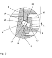
- FIG. 1 From the Fig. 1 the structure of a laser processing nozzle coupling 1 rotationally symmetrically designed with the exception of the ball assemblies is visible.
- a reversibly connectable laser processing nozzle 2 with a nozzle opening for a laser beam LS is in the closed state of the laser processing nozzle coupling 1 in a locked, fixed position, which is achieved via a positive connection by appropriate in the following explained in more detail functional surfaces and components.
- the components of the laser processing nozzle coupling 1 are connected to an associated holder 3 , via which the laser processing nozzle coupling 1 is connected to further parts of the laser processing head.
- the laser processing nozzle 2 is held by a plurality of circumferentially mounted balls 4, preferably three at a distance of 120 ° with a ball diameter of about 2 mm, positively.
- the balls 4 Due to the distribution of the balls 4 is in the Fig. 1 only one of the balls 4 visible.
- the balls 4 are movably mounted in the radial direction.
- a sliding piece 6 limits the radial movement of the balls 4 to the outside, because a portion 7 rests against the balls 4.
- the sliding piece 6 is arranged displaceably between a stop (snap ring 6a arranged in a groove) and a stop 6b .
- the sliding piece 6 can be considered as an essential actuator of the laser machining nozzle coupling 1, which must be used or actuated in an automation of the nozzle change.
- the laser processing nozzle 2 limits the radial movement of the balls 4 inwards.
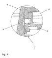
- a sliding sleeve 9 is pressed down.
- the bellows spring 8 has the task of pushing the sliding sleeve 9 down when no laser machining nozzle 2 is used.
- the spring force prevents the laser processing nozzle 2 is moved by slight collisions from its defined position upwards.
- a circumferential chamfer 10 on the laser machining nozzle 2 the balls 4 are now pressed against the sliding piece 6.
- the laser machining nozzle 2 is thus radially fixed in its position by the sleeve 5 and axially by the balls 4.
- the balls 4 To release the laser machining nozzle coupling 1, the balls 4 must be pushed radially outward. This is made possible by the sliding piece 6 in the clutch actuating direction 11 (Z direction) against the spring force of a compression spring 12 (see Fig. 1 ) is pushed upwards, whereby the balls 4 can escape into an annular space 13 .
- the compression spring 12 has the task to hold the sliding piece 6 in a defined position, so that it does not come by slight movements on the sliding piece 6 to open the laser machining nozzle clutch 1.
- the operation of the sliding piece 6 is carried out by a manual force attack or by a corresponding device or appropriate aids, such as one on the pressurizable edge 14 (see Fig. 1 ) attachable ring. In the in Fig.
- the bellows spring 8 presses on the sliding sleeve 9 on the laser machining nozzle 2.
- the sliding sleeve 9 presses the laser machining nozzle 2 down.
- the movement of the sliding sleeve 9 is by a collar 18 (see. Fig. 1 and Fig. 4 ) limited.
- the compression spring 12 thus remains taut, even if the external force attack for actuating the sliding piece 6 is omitted.
- the laser processing nozzle 2 presses first on the sliding sleeve 9, pushes it upwards, and the balls 4 can escape into the taper on the laser processing nozzle 2.
- the laser processing nozzle 2 is fixed.
- the recording of the laser processing nozzle 2 and the closing of the laser processing nozzle coupling 1 takes place analogously in the reverse order to the above-described release of the laser processing nozzle coupling 1.
- a laser processing nozzle 2 If a laser processing nozzle 2 is now inserted from below, it first pushes the sliding sleeve 9 against the spring force upwards. The sliding piece 6 is completely uninvolved in this process. The laser processing nozzle 2 now presses until the smallest nozzle diameter is at the ball height. As a result, the balls 4 can move in the direction of the beam axis, ie toward the center. When the balls 4 move in this direction, they allow the sliding piece 6, which could not be moved because of his paragraph 16, the movement down. This downward movement is supported by the spring force of the compression spring 12. The compression spring 12 pushes the sliding piece 6 back to the stop. As a result, the laser processing nozzle 2 is fixed, and for replacement of the laser processing nozzle 2, no component had to be moved with foreign assistance.
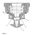
- While the first embodiment shows movement of the slide piece 6 in the Z direction of the laser processing head, it is also possible to arrange a second laser machining nozzle clutch 21 with movement in the X or Y direction (clutch operation direction 25) Fig. 6 , The clutch mechanism for releasing and closing itself is unchanged.
- a sliding piece 26 and a laser processing nozzle 22 are slidable transversely to the laser beam.
- the laser processing nozzle 22 faces one Fig. 1 modified bracket with the laser machining head and is coupled laterally across a nozzle portion 23rd A guide in a groove 24 allows lateral movement.
Claims (7)
- Dispositif d'usinage par laser (1 ; 21) comprenant une tête d'usinage par laser, une buse d'usinage par laser (2 ; 22) et un accouplement de buse d'usinage par laser (1 ; 21) servant à relier la buse d'usinage par laser (2 ; 22) à la tête d'usinage par laser, caractérisé en ce que le dispositif comprend de plus une pièce coulissante (6 ; 26), la buse d'usinage par laser (2 ; 22) et la pièce coulissante (6 ; 26) étant disposées avec possibilité de déplacement linéaire pour le desserrage et la fermeture de l'accouplement de buse d'usinage par laser (1 ; 21), ainsi qu'un manchon (5) qui présente au moins un perçage pour la réception d'une bille (4) déplaçable en direction radiale, ladite au moins une bille (4) étant, dans l'état fermé de l'accouplement de buse d'usinage par laser (1 ; 21), bloquée et fixée dans le perçage vers l'intérieur par la buse d'usinage par laser (2 ; 22) déplaçable dans le manchon (5) et vers l'extérieur par la pièce coulissante (6 ; 26) déplaçable sur le manchon (5), la bille (4) étant, dans l'état fermé, coincée entre un premier talon périphérique (15) et une surface oblique servant à l'appui de la bille (4) sur la buse d'usinage par laser (2 ; 22) et un deuxième talon périphérique (16) de la pièce coulissante (6), un déplacement de la pièce coulissante (6 ; 26) dans la direction d'actionnement d'accouplement (11, 25) étant empêché par ladite au moins une bille (4) dans l'état fermé parce que le talon (16) de la pièce coulissante (6 ; 26) ne peut pas passer devant la bille, et la buse d'usinage par laser (2) étant déplaçable depuis l'état fermé dans la direction d'actionnement d'accouplement (11, 25) pour permettre le déplacement de la pièce coulissante (6 ; 26) dans la direction d'actionnement d'accouplement (11, 25) par un mouvement radial de ladite au moins une bille (4) vers l'intérieur.
- Dispositif d'usinage par laser selon la revendication 1, caractérisé en ce que la buse d'usinage par laser (2 ; 22) est soumise à une force en direction d'une ouverture de sortie du faisceau laser (LS) au moyen d'un élément élastique (8) et que la pièce coulissante (6 ; 26) est soumise à une force en direction de l'ouverture de sortie au moyen d'un ressort de compression (12).
- Dispositif d'usinage par laser selon une ou plusieurs des revendications précédentes, caractérisé en ce que la buse d'usinage par laser (2 ; 22) et la pièce coulissante (6 ; 26) présentent des espaces libres (13, 17) pour le desserrage de l'accouplement de buse d'usinage par laser (1 ; 21).
- Dispositif d'usinage par laser selon une ou plusieurs des revendications précédentes, caractérisé en ce qu'au-dessus de la buse d'usinage par laser (2 ; 22), vu en direction d'actionnement d'accouplement (11, 25), est disposé un manchon coulissant (9) par l'intermédiaire duquel l'élément élastique (8) agit sur la buse d'usinage par laser (2 ; 22).
- Dispositif d'usinage par laser selon une ou plusieurs des revendications précédentes, caractérisé en ce que la pièce coulissante (6 ; 26) présente une surface d'attaque (bord 14) pour un moyen servant à déplacer la pièce coulissante (6 ; 26).
- Dispositif d'usinage par laser selon une ou plusieurs des revendications précédentes, caractérisé en ce que la direction de déplacement (11) de la pièce coulissante (6) et de la buse d'usinage par laser (2) est formée par la direction Z de déplacement de la tête d'usinage par laser, c'est-à-dire la direction de rayonnement du faisceau laser.
- Dispositif d'usinage par laser selon une ou plusieurs des revendications 1 à 5, caractérisé en ce que la direction de déplacement (25) de la pièce coulissante (26) et de la buse d'usinage par laser (22) est formée par la direction X ou Y de déplacement de la tête d'usinage par laser, c'est-à-dire la direction perpendiculaire au faisceau laser.
Priority Applications (5)
| Application Number | Priority Date | Filing Date | Title |
|---|---|---|---|
| AT03018178T ATE455619T1 (de) | 2003-08-09 | 2003-08-09 | Laserbearbeitungsdüsenkupplung |
| EP03018178A EP1506833B1 (fr) | 2003-08-09 | 2003-08-09 | Connection de buse laser |
| DE50312360T DE50312360D1 (de) | 2003-08-09 | 2003-08-09 | Laserbearbeitungsdüsenkupplung |
| JP2004228558A JP5095911B2 (ja) | 2003-08-09 | 2004-08-04 | レーザ加工ノズル連結部 |
| US10/913,284 US7273997B2 (en) | 2003-08-09 | 2004-08-09 | Laser processing nozzle coupling |
Applications Claiming Priority (1)
| Application Number | Priority Date | Filing Date | Title |
|---|---|---|---|
| EP03018178A EP1506833B1 (fr) | 2003-08-09 | 2003-08-09 | Connection de buse laser |
Publications (2)
| Publication Number | Publication Date |
|---|---|
| EP1506833A1 EP1506833A1 (fr) | 2005-02-16 |
| EP1506833B1 true EP1506833B1 (fr) | 2010-01-20 |
Family
ID=33560771
Family Applications (1)
| Application Number | Title | Priority Date | Filing Date |
|---|---|---|---|
| EP03018178A Expired - Lifetime EP1506833B1 (fr) | 2003-08-09 | 2003-08-09 | Connection de buse laser |
Country Status (5)
| Country | Link |
|---|---|
| US (1) | US7273997B2 (fr) |
| EP (1) | EP1506833B1 (fr) |
| JP (1) | JP5095911B2 (fr) |
| AT (1) | ATE455619T1 (fr) |
| DE (1) | DE50312360D1 (fr) |
Families Citing this family (11)
| Publication number | Priority date | Publication date | Assignee | Title |
|---|---|---|---|---|
| JP4723456B2 (ja) | 2006-10-27 | 2011-07-13 | 三菱電機株式会社 | 加工ヘッドおよびノズル交換装置およびレーザ加工装置 |
| DE102007024288B3 (de) | 2007-05-23 | 2008-10-16 | Trumpf Werkzeugmaschinen Gmbh + Co. Kg | Anordnung zur Erkennung einer Laserbearbeitungsdüse beim Einsetzen der Laserbearbeitungsdüse in einen Laserbearbeitungskopf |
| FR2975318B1 (fr) * | 2011-05-16 | 2014-05-09 | Air Liquide | Buse laser a element mobile |
| EP2674238B1 (fr) * | 2012-06-15 | 2017-09-27 | Agie Charmilles New Technologies SA | Machine laser avec un attache outil comprenant un système de guidage/blocage |
| JP6139918B2 (ja) * | 2013-03-06 | 2017-05-31 | 株式会社アマダホールディングス | レーザ加工機 |
| DE202017103742U1 (de) | 2017-06-23 | 2017-07-18 | Trumpf Laser Gmbh | Steckeraufnahme für einen Faserstecker eines Lichtleitkabels |
| EP3466597A1 (fr) | 2017-10-05 | 2019-04-10 | Synova S.A. | Appareil d'usinage d'une pièce par faisceau laser |
| EP3470165B1 (fr) * | 2017-10-13 | 2023-08-16 | Synova S.A. | Appareil d'usinage d'une pièce au moyen d'un faisceau laser guidé par un jet liquide et son assemblage |
| CN114258334A (zh) * | 2019-06-25 | 2022-03-29 | 海别得公司 | 材料加工系统中的锁定机构 |
| DE102022112050A1 (de) | 2022-05-13 | 2023-11-16 | TRUMPF Werkzeugmaschinen SE + Co. KG | Düse für die Laserbearbeitung mit hohen Fokuslagen |
| CN115074727B (zh) * | 2022-06-30 | 2023-04-18 | 江西制造职业技术学院 | 一种激光熔覆气氛保护装置 |
Family Cites Families (34)
| Publication number | Priority date | Publication date | Assignee | Title |
|---|---|---|---|---|
| US3247978A (en) * | 1962-12-12 | 1966-04-26 | Programmed & Remote Syst Corp | Manipulator hand |
| US3761117A (en) * | 1972-04-19 | 1973-09-25 | Crawford Fitting Co | Quick connect fitting |
| US4114853A (en) * | 1976-10-08 | 1978-09-19 | Swagelok Company | Quick connect coupling |
| GB2089918B (en) * | 1980-12-19 | 1984-03-28 | Harwood Royston Peter | Quick-connect coupling |
| JPS58186589A (ja) * | 1982-04-27 | 1983-10-31 | 富士通フアナツク株式会社 | 工業用ロボツトのハンド交換装置 |
| US4598581A (en) * | 1984-06-25 | 1986-07-08 | Fmc Corporation | Quick connect diagnostic system |
| US4733457A (en) * | 1985-02-04 | 1988-03-29 | Metalmeccanica Gori & Zucchi M.G.Z. S.P.A. | Apparatus for the automation of operative systems with mechanical hand or the like |
| US4740058A (en) * | 1986-08-29 | 1988-04-26 | Technology For Imaging, Inc. | Coupler for optical instruments |
| USRE34426E (en) * | 1987-11-05 | 1993-11-02 | Production Control Units, Inc. | Dispensing tool assembly for charging a refrigerant into a system |
| US4966398A (en) * | 1989-02-14 | 1990-10-30 | Buell Industries, Inc. | Fluid conduit coupling |
| IT1233073B (it) * | 1989-08-01 | 1992-03-14 | Prima Ind Spa | Macchina laser per l effettuazione di lavorazioni di taglio e saldatu ra |
| IT1239874B (it) * | 1990-01-31 | 1993-11-15 | Comau Spa | Dispositivo per la saldatura laser di scocche di autoveicoli |
| DE9004335U1 (fr) * | 1990-04-14 | 1990-07-26 | Trumpf Gmbh & Co, 7257 Ditzingen, De | |
| JP2505624B2 (ja) * | 1990-06-28 | 1996-06-12 | ビー・エル・オートテック株式会社 | ロボットア―ムカップリング装置用マスタプレ―ト及びツ―ルプレ―ト並びにそれらを組み合わせたロボットア―ムカップリング装置 |
| US5074332A (en) * | 1990-08-16 | 1991-12-24 | Production Control Units, Inc. | Hose coupling unit for refrigerant system |
| JPH0518487A (ja) * | 1991-07-10 | 1993-01-26 | Sekisui Chem Co Ltd | 管の接続部構造 |
| GB2299777B (en) * | 1995-04-01 | 1998-07-22 | M J Tech Ltd | Laser materials working apparatus |
| JPH106062A (ja) * | 1996-06-24 | 1998-01-13 | Amada Co Ltd | Yagレーザー加工ヘッド及び同加工ヘッドに使用するレーザー加工用ノズル及び同レーザー加工用ノズルのノズルマガジン |
| US5897795A (en) * | 1996-10-08 | 1999-04-27 | Hypertherm, Inc. | Integral spring consumables for plasma arc torch using blow forward contact starting system |
| DE29718726U1 (de) * | 1997-10-10 | 1999-02-18 | Kuka Schweissanlagen Gmbh | Wechselkupplung |
| US5896889A (en) * | 1997-10-24 | 1999-04-27 | Menard; Orville R. | Quick-set hydraulic coupler |
| US6058971A (en) * | 1998-08-31 | 2000-05-09 | Seychelle Environmental Technologies, Inc. | Quick-connect diverter valve |
| JP3198095B2 (ja) * | 1998-10-21 | 2001-08-13 | ファナック株式会社 | レーザ加工装置 |
| GB9903148D0 (en) * | 1999-02-12 | 1999-04-07 | Henrob Ltd | Fastener delivery apparatus |
| US6234274B1 (en) * | 1999-04-23 | 2001-05-22 | K. J. Manufacturing, Inc. | Low profile nipple |
| DE10056330C1 (de) | 1999-09-16 | 2002-03-07 | Precitec Kg | Wechselvorrichtung für einen Linsenhalter eines Anschlußkopfs zur Bearbeitung eines Werkstücks mittels eines Laserstrahls |
| DE19944484C1 (de) | 1999-09-16 | 2001-04-19 | Precitec Gmbh | Wechselvorrichtung für einen Linsenhalter eines Anschlusskopfs zur Bearbeitung eines Werkstücks mittels eines Laserstrahls |
| US6534745B1 (en) * | 1999-09-27 | 2003-03-18 | Mathew T. J. Lowney | Nozzle particularly suited to direct metal deposition |
| US6315544B1 (en) * | 1999-10-07 | 2001-11-13 | Burger Engineering, Inc. | Adjustable length extension bars for connecting a mold ejector plate to a press ejector plate |
| US6206694B1 (en) * | 1999-11-24 | 2001-03-27 | Crystalmark Dental Systems, Inc. | Handpiece assembly for air abrasion |
| JP4481446B2 (ja) * | 2000-07-11 | 2010-06-16 | サーパス工業株式会社 | 複数流路を有するコネクタ |
| JP2002160085A (ja) * | 2000-11-14 | 2002-06-04 | Precitec Kg | レーザ加工接続ヘッドのレンズホルダ用交換装置 |
| IT1321095B1 (it) * | 2000-12-13 | 2003-12-30 | Com Imp Ex Di Elio Strobietto | Dispositivo automatico di cambio di utensile per un robot di tipoindustriale. |
| US6761361B2 (en) * | 2002-08-09 | 2004-07-13 | Credo Technology Corporation | Drill and drive apparatus with improved tool holder |
-
2003
- 2003-08-09 AT AT03018178T patent/ATE455619T1/de not_active IP Right Cessation
- 2003-08-09 DE DE50312360T patent/DE50312360D1/de not_active Expired - Lifetime
- 2003-08-09 EP EP03018178A patent/EP1506833B1/fr not_active Expired - Lifetime
-
2004
- 2004-08-04 JP JP2004228558A patent/JP5095911B2/ja not_active Expired - Fee Related
- 2004-08-09 US US10/913,284 patent/US7273997B2/en active Active
Also Published As
| Publication number | Publication date |
|---|---|
| US20050061790A1 (en) | 2005-03-24 |
| EP1506833A1 (fr) | 2005-02-16 |
| JP5095911B2 (ja) | 2012-12-12 |
| DE50312360D1 (de) | 2010-03-11 |
| ATE455619T1 (de) | 2010-02-15 |
| JP2005059099A (ja) | 2005-03-10 |
| US7273997B2 (en) | 2007-09-25 |
Similar Documents
| Publication | Publication Date | Title |
|---|---|---|
| EP3569335B1 (fr) | Dispositif de levage magnétique pour une fraiseuse | |
| EP1506833B1 (fr) | Connection de buse laser | |
| DE2360337A1 (de) | Werkzeugspannvorrichtung | |
| DE1477578B2 (de) | Numerisch gesteuerte werkzeugmaschine | |
| EP2576133B1 (fr) | Tourelle revolver | |
| EP0451360A2 (fr) | Dispositif de serrage pour la fixation d'un outil dans un porte-outil | |
| EP2552643B1 (fr) | Dispositif de fixation pour la fixation d'un mandrin de serrage sur une broche rotative | |
| EP3641986B1 (fr) | Système de serrage ayant une fonction dite de troisième main | |
| EP0137961B2 (fr) | Dispositif extracteur pour une brique pour lavage au gaz | |
| DE102004010987B4 (de) | Sicherungseinheit | |
| DE2812200C2 (fr) | ||
| EP3771510A1 (fr) | Machine-outil dotée d'un porte-outil mobile, porte-outil et support d'outil correspondant | |
| EP0179325A2 (fr) | Dispositif de serrage avec bride oscillante | |
| EP1237704A1 (fr) | Dispositif et procede permettant de realiser un mouvement lineaire en deux temps | |
| DE102015222785B3 (de) | Spanneinrichtung | |
| EP0568858B1 (fr) | Dispositif de verrouillage d'un piston commandé par pression, en particulier pour la commande d'une barre antirenversement d'un véhicule | |
| EP3535102B1 (fr) | Outil et dispositif permettant d'enlever de la matière des surfaces | |
| EP1033196A1 (fr) | Dispositif de serrage de pièces à usiner | |
| DE102010021948A1 (de) | Werkzeugrevolver | |
| DE102019218402B4 (de) | Federdom für ein Hydraulikventil und Hydraulikventil mit einem solchen Federdom | |
| DE102019123119B3 (de) | Mobile Vorrichtung zur spanenden Bearbeitung eines Werkstücks | |
| DE3215899A1 (de) | Kraftbetaetigtes schwenkfutter | |
| EP1555087B1 (fr) | Dispositif permettant le pivotement des pièces ou des dispositifs dans des machines outils | |
| DE202015008075U1 (de) | Spanneinrichtung | |
| DE102021106197A1 (de) | Spindelaggregat |
Legal Events
| Date | Code | Title | Description |
|---|---|---|---|
| PUAI | Public reference made under article 153(3) epc to a published international application that has entered the european phase |
Free format text: ORIGINAL CODE: 0009012 |
|
| AK | Designated contracting states |
Kind code of ref document: A1 Designated state(s): AT BE BG CH CY CZ DE DK EE ES FI FR GB GR HU IE IT LI LU MC NL PT RO SE SI SK TR |
|
| AX | Request for extension of the european patent |
Extension state: AL LT LV MK |
|
| 17P | Request for examination filed |
Effective date: 20050804 |
|
| AKX | Designation fees paid |
Designated state(s): AT BE BG CH CY CZ DE DK EE ES FI FR GB GR HU IE IT LI LU MC NL PT RO SE SI SK TR |
|
| 17Q | First examination report despatched |
Effective date: 20061027 |
|
| GRAP | Despatch of communication of intention to grant a patent |
Free format text: ORIGINAL CODE: EPIDOSNIGR1 |
|
| GRAS | Grant fee paid |
Free format text: ORIGINAL CODE: EPIDOSNIGR3 |
|
| GRAA | (expected) grant |
Free format text: ORIGINAL CODE: 0009210 |
|
| AK | Designated contracting states |
Kind code of ref document: B1 Designated state(s): AT BE BG CH CY CZ DE DK EE ES FI FR GB GR HU IE IT LI LU MC NL PT RO SE SI SK TR |
|
| REG | Reference to a national code |
Ref country code: GB Ref legal event code: FG4D Free format text: NOT ENGLISH |
|
| REG | Reference to a national code |
Ref country code: CH Ref legal event code: EP |
|
| REG | Reference to a national code |
Ref country code: IE Ref legal event code: FG4D |
|
| REF | Corresponds to: |
Ref document number: 50312360 Country of ref document: DE Date of ref document: 20100311 Kind code of ref document: P |
|
| REG | Reference to a national code |
Ref country code: NL Ref legal event code: VDEP Effective date: 20100120 |
|
| PG25 | Lapsed in a contracting state [announced via postgrant information from national office to epo] |
Ref country code: ES Free format text: LAPSE BECAUSE OF FAILURE TO SUBMIT A TRANSLATION OF THE DESCRIPTION OR TO PAY THE FEE WITHIN THE PRESCRIBED TIME-LIMIT Effective date: 20100501 Ref country code: PT Free format text: LAPSE BECAUSE OF FAILURE TO SUBMIT A TRANSLATION OF THE DESCRIPTION OR TO PAY THE FEE WITHIN THE PRESCRIBED TIME-LIMIT Effective date: 20100520 Ref country code: NL Free format text: LAPSE BECAUSE OF FAILURE TO SUBMIT A TRANSLATION OF THE DESCRIPTION OR TO PAY THE FEE WITHIN THE PRESCRIBED TIME-LIMIT Effective date: 20100120 |
|
| REG | Reference to a national code |
Ref country code: IE Ref legal event code: FD4D |
|
| PG25 | Lapsed in a contracting state [announced via postgrant information from national office to epo] |
Ref country code: SI Free format text: LAPSE BECAUSE OF FAILURE TO SUBMIT A TRANSLATION OF THE DESCRIPTION OR TO PAY THE FEE WITHIN THE PRESCRIBED TIME-LIMIT Effective date: 20100120 Ref country code: FI Free format text: LAPSE BECAUSE OF FAILURE TO SUBMIT A TRANSLATION OF THE DESCRIPTION OR TO PAY THE FEE WITHIN THE PRESCRIBED TIME-LIMIT Effective date: 20100120 |
|
| PLBI | Opposition filed |
Free format text: ORIGINAL CODE: 0009260 |
|
| PG25 | Lapsed in a contracting state [announced via postgrant information from national office to epo] |
Ref country code: RO Free format text: LAPSE BECAUSE OF FAILURE TO SUBMIT A TRANSLATION OF THE DESCRIPTION OR TO PAY THE FEE WITHIN THE PRESCRIBED TIME-LIMIT Effective date: 20100120 Ref country code: SE Free format text: LAPSE BECAUSE OF FAILURE TO SUBMIT A TRANSLATION OF THE DESCRIPTION OR TO PAY THE FEE WITHIN THE PRESCRIBED TIME-LIMIT Effective date: 20100120 Ref country code: CY Free format text: LAPSE BECAUSE OF FAILURE TO SUBMIT A TRANSLATION OF THE DESCRIPTION OR TO PAY THE FEE WITHIN THE PRESCRIBED TIME-LIMIT Effective date: 20100120 Ref country code: GR Free format text: LAPSE BECAUSE OF FAILURE TO SUBMIT A TRANSLATION OF THE DESCRIPTION OR TO PAY THE FEE WITHIN THE PRESCRIBED TIME-LIMIT Effective date: 20100421 Ref country code: IE Free format text: LAPSE BECAUSE OF FAILURE TO SUBMIT A TRANSLATION OF THE DESCRIPTION OR TO PAY THE FEE WITHIN THE PRESCRIBED TIME-LIMIT Effective date: 20100120 Ref country code: EE Free format text: LAPSE BECAUSE OF FAILURE TO SUBMIT A TRANSLATION OF THE DESCRIPTION OR TO PAY THE FEE WITHIN THE PRESCRIBED TIME-LIMIT Effective date: 20100120 |
|
| PLAX | Notice of opposition and request to file observation + time limit sent |
Free format text: ORIGINAL CODE: EPIDOSNOBS2 |
|
| 26 | Opposition filed |
Opponent name: HOLMA AG LASER & PLASMA CONSUMABLES Effective date: 20101019 |
|
| PG25 | Lapsed in a contracting state [announced via postgrant information from national office to epo] |
Ref country code: BG Free format text: LAPSE BECAUSE OF FAILURE TO SUBMIT A TRANSLATION OF THE DESCRIPTION OR TO PAY THE FEE WITHIN THE PRESCRIBED TIME-LIMIT Effective date: 20100420 Ref country code: CZ Free format text: LAPSE BECAUSE OF FAILURE TO SUBMIT A TRANSLATION OF THE DESCRIPTION OR TO PAY THE FEE WITHIN THE PRESCRIBED TIME-LIMIT Effective date: 20100120 Ref country code: SK Free format text: LAPSE BECAUSE OF FAILURE TO SUBMIT A TRANSLATION OF THE DESCRIPTION OR TO PAY THE FEE WITHIN THE PRESCRIBED TIME-LIMIT Effective date: 20100120 |
|
| PG25 | Lapsed in a contracting state [announced via postgrant information from national office to epo] |
Ref country code: DK Free format text: LAPSE BECAUSE OF FAILURE TO SUBMIT A TRANSLATION OF THE DESCRIPTION OR TO PAY THE FEE WITHIN THE PRESCRIBED TIME-LIMIT Effective date: 20100120 |
|
| BERE | Be: lapsed |
Owner name: TRUMPF WERKZEUGMASCHINEN G.M.B.H. + CO. KG Effective date: 20100831 |
|
| PLAF | Information modified related to communication of a notice of opposition and request to file observations + time limit |
Free format text: ORIGINAL CODE: EPIDOSCOBS2 |
|
| PG25 | Lapsed in a contracting state [announced via postgrant information from national office to epo] |
Ref country code: MC Free format text: LAPSE BECAUSE OF NON-PAYMENT OF DUE FEES Effective date: 20100831 Ref country code: IT Free format text: LAPSE BECAUSE OF FAILURE TO SUBMIT A TRANSLATION OF THE DESCRIPTION OR TO PAY THE FEE WITHIN THE PRESCRIBED TIME-LIMIT Effective date: 20100120 |
|
| GBPC | Gb: european patent ceased through non-payment of renewal fee |
Effective date: 20100809 |
|
| REG | Reference to a national code |
Ref country code: FR Ref legal event code: ST Effective date: 20110502 |
|
| PLBB | Reply of patent proprietor to notice(s) of opposition received |
Free format text: ORIGINAL CODE: EPIDOSNOBS3 |
|
| PG25 | Lapsed in a contracting state [announced via postgrant information from national office to epo] |
Ref country code: FR Free format text: LAPSE BECAUSE OF NON-PAYMENT OF DUE FEES Effective date: 20100831 Ref country code: BE Free format text: LAPSE BECAUSE OF NON-PAYMENT OF DUE FEES Effective date: 20100831 |
|
| PG25 | Lapsed in a contracting state [announced via postgrant information from national office to epo] |
Ref country code: GB Free format text: LAPSE BECAUSE OF NON-PAYMENT OF DUE FEES Effective date: 20100809 |
|
| PG25 | Lapsed in a contracting state [announced via postgrant information from national office to epo] |
Ref country code: AT Free format text: LAPSE BECAUSE OF NON-PAYMENT OF DUE FEES Effective date: 20100809 |
|
| PLCK | Communication despatched that opposition was rejected |
Free format text: ORIGINAL CODE: EPIDOSNREJ1 |
|
| PG25 | Lapsed in a contracting state [announced via postgrant information from national office to epo] |
Ref country code: LU Free format text: LAPSE BECAUSE OF NON-PAYMENT OF DUE FEES Effective date: 20100809 Ref country code: HU Free format text: LAPSE BECAUSE OF FAILURE TO SUBMIT A TRANSLATION OF THE DESCRIPTION OR TO PAY THE FEE WITHIN THE PRESCRIBED TIME-LIMIT Effective date: 20100721 |
|
| PLBN | Opposition rejected |
Free format text: ORIGINAL CODE: 0009273 |
|
| STAA | Information on the status of an ep patent application or granted ep patent |
Free format text: STATUS: OPPOSITION REJECTED |
|
| PG25 | Lapsed in a contracting state [announced via postgrant information from national office to epo] |
Ref country code: TR Free format text: LAPSE BECAUSE OF FAILURE TO SUBMIT A TRANSLATION OF THE DESCRIPTION OR TO PAY THE FEE WITHIN THE PRESCRIBED TIME-LIMIT Effective date: 20100120 |
|
| 27O | Opposition rejected |
Effective date: 20120626 |
|
| REG | Reference to a national code |
Ref country code: DE Ref legal event code: R100 Ref document number: 50312360 Country of ref document: DE Effective date: 20120626 |
|
| PGFP | Annual fee paid to national office [announced via postgrant information from national office to epo] |
Ref country code: CH Payment date: 20200819 Year of fee payment: 18 |
|
| PGFP | Annual fee paid to national office [announced via postgrant information from national office to epo] |
Ref country code: DE Payment date: 20210819 Year of fee payment: 19 |
|
| REG | Reference to a national code |
Ref country code: CH Ref legal event code: PL |
|
| PG25 | Lapsed in a contracting state [announced via postgrant information from national office to epo] |
Ref country code: LI Free format text: LAPSE BECAUSE OF NON-PAYMENT OF DUE FEES Effective date: 20210831 Ref country code: CH Free format text: LAPSE BECAUSE OF NON-PAYMENT OF DUE FEES Effective date: 20210831 |
|
| REG | Reference to a national code |
Ref country code: DE Ref legal event code: R119 Ref document number: 50312360 Country of ref document: DE |
|
| PG25 | Lapsed in a contracting state [announced via postgrant information from national office to epo] |
Ref country code: DE Free format text: LAPSE BECAUSE OF NON-PAYMENT OF DUE FEES Effective date: 20230301 |