EP1505233A2 - Kantengetriebe - Google Patents
Kantengetriebe Download PDFInfo
- Publication number
- EP1505233A2 EP1505233A2 EP04102785A EP04102785A EP1505233A2 EP 1505233 A2 EP1505233 A2 EP 1505233A2 EP 04102785 A EP04102785 A EP 04102785A EP 04102785 A EP04102785 A EP 04102785A EP 1505233 A2 EP1505233 A2 EP 1505233A2
- Authority
- EP
- European Patent Office
- Prior art keywords
- housing parts
- faceplate
- edge gear
- tabs
- edge
- Prior art date
- Legal status (The legal status is an assumption and is not a legal conclusion. Google has not performed a legal analysis and makes no representation as to the accuracy of the status listed.)
- Withdrawn
Links
Images
Classifications
-
- E—FIXED CONSTRUCTIONS
- E05—LOCKS; KEYS; WINDOW OR DOOR FITTINGS; SAFES
- E05C—BOLTS OR FASTENING DEVICES FOR WINGS, SPECIALLY FOR DOORS OR WINDOWS
- E05C9/00—Arrangements of simultaneously actuated bolts or other securing devices at well-separated positions on the same wing
- E05C9/02—Arrangements of simultaneously actuated bolts or other securing devices at well-separated positions on the same wing with one sliding bar for fastening when moved in one direction and unfastening when moved in opposite direction; with two sliding bars moved in the same direction when fastening or unfastening
- E05C9/021—Arrangements of simultaneously actuated bolts or other securing devices at well-separated positions on the same wing with one sliding bar for fastening when moved in one direction and unfastening when moved in opposite direction; with two sliding bars moved in the same direction when fastening or unfastening with rack and pinion mechanism
-
- E—FIXED CONSTRUCTIONS
- E05—LOCKS; KEYS; WINDOW OR DOOR FITTINGS; SAFES
- E05C—BOLTS OR FASTENING DEVICES FOR WINGS, SPECIALLY FOR DOORS OR WINDOWS
- E05C9/00—Arrangements of simultaneously actuated bolts or other securing devices at well-separated positions on the same wing
- E05C9/004—Faceplates ; Fixing the faceplates to the wing
Definitions
- the invention relates to an edge gear, which for Attachment to a faceplate of an espagnolette fitting is provided, with one between two housing parts stored and intervene in a at the Faceplate guided drive rod provided drive pinion, with arranged on the housing parts, for support provided on the faceplate support elements and with the engaging behind on the support elements Side of the faceplate rail provided the Housing parts, with the tabs on the faceplate fastened state penetrate recesses of the faceplate, the tabs of the faceplate of one of Recesses of the face plate guide position in a the reticle behind engaging position plastically are deformable.
- Such edge gears are used to drive on the faceplate guided Espagnolettes at espagnolette fittings used.
- the drive pinion usually has a Square recess on top of it with a handle is connected.
- Such an edge gear is for example from the DE - OS - 2 033 042.
- this edge gear have the housing parts along more abutting End edges cams, with which they are in a common Recess recess of the faceplate fit accurately.
- the housing parts rivet bolts, with which they through further recesses of the faceplate passed through and riveted there.
- the cams transmit reaction forces of the drive pinion on the Faceplate and are supported on the faceplate rail Transverse walls arranged.
- the drive rod is thus guided between the transverse walls and the drive pinion.
- the disadvantage of this edge gear is that it by the arrangement of the transverse walls between the drive rod and the faceplate has very large dimensions and very difficult to manufacture.
- the Components of the edge gear during assembly at the Cuff rail be assembled, since the transverse walls of the Housing parts are guided under the drive rod. Therefore First, the housing parts are single with the cams and the rivet bolt in the recesses of the faceplate to lead while maintaining the drive pinion between the Use housing parts. At the end of the assembly will be the rivet bolt riveted to the faceplate. A cost-effective pre-assembly of the housing parts with the drive pinion is not possible with this edge gear.
- an edge gear in which a single housing part a Recess for a centrally arranged cylindrical Section of the drive pinion has. On both sides of the cylindrical portion are arranged teeth, which in corresponding recesses of the drive rod penetrate. The tabs are at the ends of the single housing part arranged and riveted to the faceplate. About the only housing part can transmit only small forces.
- the drive pinion must during assembly of the edge gear on the face plate in the housing part be used. An inexpensive pre-assembly This edge gear is also not possible.
- the invention is based on the problem of an edge gear of the type mentioned above to be designed so that It is especially easily pre-stocked and kept in stock pre-assembled state to be connected to the faceplate can.
- the housing parts with the initially mounted therein drive pinion against each other fixed.
- the edge gear pre-assembled edge gear with the support elements pressed against the faceplate. Penetrate it the tabs the recesses of the faceplate and overhang this slightly. The sections will follow plastically deformed and thus the edge gear on the Face-plate fastened.
- the fixation of the housing parts against each other for example, cohesively Welding or gluing or positive locking by riveting or interlocking hooks take place.
- the fixation of the housing parts against each other the housing parts no between the faceplate and the Drive rod to be arranged transverse walls, as in the known Edge gear.
- the assembly of the edge gear according to the invention on the Faceplate is particularly simple when the Latches a first, one of the thickness of the faceplate corresponding length section and a adjoining the first section, across this aligned second section.
- This Design allows the tabs simply through the recesses pass the faceplate.
- It towers over the second section is the faceplate on the drive pinion opposite side and can be for positive locking Attaching the edge gear to the faceplate turn to the side. This is either the first Section twisted or the second section bent. This allows a high stability of the attachment generate at low assembly forces.
- the means for fixing the housing parts require according to another advantageous embodiment of the invention a particularly low design effort when the Housing parts have mutually penetrating rivets.
- it is by riveting the housing parts possible by means of rivets, the housing parts after the Assemble a positive fit with each other and so that the edge gear according to the invention as finished assembled Keep unit in stock.
- connection of the edge gear according to the invention with the faceplate has a particularly high strength on, if several tabs in a row each Longitudinal sides of the housing parts are arranged.
- the manufacture of the housing parts is designed according to a another advantageous embodiment of the invention particularly inexpensive, if the housing parts as pressed sheet metal parts are formed.
- a risk of injury to the cuff rail superior Sections of the tabs can be according to another advantageous development of the invention simple Avoid when a cover element locking means for connection with the cuff rail protruding sections the tabs has.
- the cover can be according to another advantageous Development of the invention particularly cost finished when the cover made of plastic is.
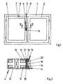
- FIG. 1 shows a window with a frame 1 with two Wings 2, 3.
- the left wing 2 has one of an edge gear 4 drivable drive rod fitting 5 with a Drive rod 6.
- the drive rod 6 carries in strike plates 7 of the frame 1 hineinbewegbare locking pin 8.
- Bei the right wing 3 may be, for example, a Cleaning blades act, which only after opening of the left wing 2 can unlock.
- the wings 2, 3 are thus locked in a frame 1 with the locked Status.
- the edge gear 4 can be via a Drive 9 drive and thus the drive rod 6 in her Move longitudinally.
- FIG 2 shows an enlarged sectional view along the line II - II through the edge gear 4 from Figure 1 that a drive pinion 10 between two housing parts 11, 12 is stored.
- the drive pinion 10 engages in the guided on a cuff rail 13 Driving rod 6 a.
- the housing parts 11, 12 each have Lugs 14, 15, with which they the faceplate 13th penetrate.
- the tabs 14, 15 are on the Drive rod 6 opposite side of the faceplate 13 entangled and attach the edge gear 4 to the faceplate 13.
- Support members 16, 17 are located on the faceplate 13 and secure the drive pinion 10 in a relation to the Driving rod 6 provided location.
- a cover 18 from Plastic has latching means 19, 20, with which it the tabs 14, 15 is attached.
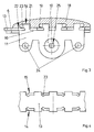
- Figure 3 shows the attached to the faceplate 13 edge gear 4 of Figure 2 in a side view.
- the cover element 19 is cut to simplify the drawing shown.
- the tabs 14 of the housing part 11 have a first portion 21, with which they recesses 22 of the faceplate 13 penetrate and have a transverse to the first section 21 extending second Section 23.
- the second section 23 is crossed and thus from the region of the recesses 22 of the faceplate 13 bent out. This will be the edge gear 4 positively held on the faceplate 13.
- the two Housing parts 11, 12 of the edge gear 4 have rivets 24 for their mutual fixation.
- the drive pinion 10 is a square recess 25 for connection with that shown in FIG Handle 9 has.
- the edge gear 4 can first be pre-assembled, by the drive pinion 10 between the housing parts 11, 12 is used, and the housing parts 11, 12 then be connected to each other via the rivets 24. In this pre-assembled state, the edge gear can be 4 keep in stock and ready for mounting with the still unver consequenten tabs 14, 15 in the recesses Insert 22 of the faceplate 13 until the support elements 16, 17 against the faceplate 13 and thus the drive pinion 10 in the intended position relative to the Drive rod 6 arrive. Subsequently, tabs 14, 15 from the region of the recesses 22 of the faceplate 13 bent out and thus the edge gear 4 form fit connected to the faceplate 13.
- Figure 4 shows in a plan view of the edge gear 4 side facing away from Figure 2 of the faceplate 13th the connection with the tabs 14, 15 of the housing parts 11, 12. It can be seen that free ends of the Faceplate 13 protruding portions 23 of the tabs 14, 15 to the side and thus from the area of the recesses 22 of the faceplate 13 are bent out. each other opposite tabs 14, 15 are thus on each other too bent. For clarity, the cover 18 not shown in Figure 3 in Figure 4.
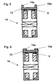
- Figs. 5 and 6 show an alternative embodiment of the in Fig. 2 illustrated edge gear in a rotated by 90 ° Presentation.
- this has Edge gear 4 second tabs 14a, 15a, with which they penetrate the faceplate 13.
- the tabs are on the drive rod 6 facing away from the faceplate flanged by about 90 °.
- Fig. 5 shows the State of the tabs 14a, 15a initial state while in Fig. 6 shows the state after the flanging is shown.
- the axis around which the flanging takes place, runs thereby parallel to the longitudinal axis of the faceplate 13.
Landscapes
- Engineering & Computer Science (AREA)
- Mechanical Engineering (AREA)
- General Details Of Gearings (AREA)
- Window Of Vehicle (AREA)
- Lock And Its Accessories (AREA)
Abstract
Description
- Fig.1
- ein Fenster mit zwei in einem Rahmen verriegelten Flügel und mit einem erfindungsgemäßen Kantengetriebe,
- Fig.2
- vergrößert eine Schnittdarstellung durch das Kantengetriebe aus Figur 1 entlang der Linie II - II,
- Fig.3
- eine Seitenansicht des an einer Stulpschiene befestigten Kantengetriebes aus Figur 2,
- Fig.4
- eine Ansicht auf die Stulpschiene im Bereich des Kantengetriebes.
- Fig.5
- eine alternative Ausgestaltung des Kantengetriebes entsprechend Fig. 2 in einer ersten Position.
- Fig.6
- eine alternative Ausgestaltung des Kantengetriebes entsprechend Fig. 2 in einer zweiten Position.
Claims (7)
- Kantengetriebe, welches zur Befestigung an einer Stulpschiene eines Treibstangenbeschlages vorgesehen ist, mit einem zwischen zwei Gehäuseteilen gelagerten und zum Eingreifen in eine an der Stulpschiene geführte Treibstange vorgesehenen Antriebsritzel, mit an den Gehäuseteilen angeordneten, zur Abstützung an der Stulpschiene vorgesehenen Stützelementen und mit zum Hintergreifen auf der den Stützelementen abgewandten Seite der Stulpschiene vorgesehenen Laschen der Gehäuseteile, wobei die Laschen im an die Stulpschiene befestigten Zustand Ausnehmungen der Stulpschiene durchdringen, wobei die Laschen der Stulpschiene von einer die Ausnehmungen der Stulpschiene hindurchführbaren Stellung in eine die Stulpschiene hintergreifende Stellung plastisch verformbar sind, dadurch gekennzeichnet, dass die Gehäuseteile (11, 12) Mittel zu ihrer gegenseitigen Fixierung aufweisen und dass im zusammengesetzten Zustand der Gehäuseteile (11, 12) die Laschen (14, 14a, 15, 15a) durch die Ausnehmungen (22) der Stulpschiene (13) hindurchführbar sind.
- Kantengetriebe nach Anspruch 1, dadurch gekennzeichnet, dass die Laschen (14, 14a, 15, 15a) einen ersten, eine der Dicke der Stulpschiene (13) entsprechende Länge aufweisenden Abschnitt (21) und einen sich an den ersten Abschnitt (21) anschließenden, quer zu diesem ausgerichteten zweiten Abschnitt (23) aufweisen.
- Kantengetriebe nach Anspruch 1 oder 2, dadurch gekennzeichnet, dass die Gehäuseteile (11, 12) sich gegenseitig durchdringende Nieten (24) aufweisen.
- Kantengetriebe nach zumindest einem der vorhergehenden Ansprüche, dadurch gekennzeichnet, dass mehrere Laschen (14, 14a, 15, 15a) in einer Reihe jeweils an Längsseiten der Gehäuseteile (11, 12) angeordnet sind.
- Kantengetriebe nach zumindest einem der vorhergehenden Ansprüche, dadurch gekennzeichnet, dass die Gehäuseteile (11, 12) als Pressblechteile ausgebildet sind.
- Kantengetriebe nach zumindest einem der vorhergehenden Ansprüche, dadurch gekennzeichnet, dass ein Abdeckelement (18) Rastmittel (19, 20) zur Verbindung mit den die Stulpschiene (13) überragenden Abschnitten (23) der Laschen (14, 14a, 15, 15a) aufweist.
- Kantengetriebe nach zumindest einem der vorhergehenden Ansprüche, dadurch gekennzeichnet, dass das Abdeckelement (18) aus Kunststoff gefertigt ist.
Applications Claiming Priority (2)
| Application Number | Priority Date | Filing Date | Title |
|---|---|---|---|
| DE10336149 | 2003-08-07 | ||
| DE2003136149 DE10336149A1 (de) | 2003-08-07 | 2003-08-07 | Kantengetriebe |
Publications (2)
| Publication Number | Publication Date |
|---|---|
| EP1505233A2 true EP1505233A2 (de) | 2005-02-09 |
| EP1505233A3 EP1505233A3 (de) | 2007-12-26 |
Family
ID=33547121
Family Applications (1)
| Application Number | Title | Priority Date | Filing Date |
|---|---|---|---|
| EP04102785A Withdrawn EP1505233A3 (de) | 2003-08-07 | 2004-06-17 | Kantengetriebe |
Country Status (2)
| Country | Link |
|---|---|
| EP (1) | EP1505233A3 (de) |
| DE (1) | DE10336149A1 (de) |
Family Cites Families (10)
| Publication number | Priority date | Publication date | Assignee | Title |
|---|---|---|---|---|
| DE1835749U (de) * | 1961-06-08 | 1961-07-27 | Heinrich Strenger Fa | Kantenbaskuelverschluss fuer fenster od. dgl. |
| FR1331434A (fr) * | 1962-05-21 | 1963-07-05 | Ferco | Crémone-verrou |
| FR1461604A (fr) * | 1965-10-21 | 1966-12-09 | Massard Jean Ets | Perfectionnements aux crémones à larder |
| DE1708183C3 (de) * | 1968-01-27 | 1978-09-28 | Siegenia-Frank Kg, 5900 Siegen- Kaan-Marienborn | Einsteckgetriebe eines Treibstangenbeschlages für Fenster, Türen od.dgl |
| DE2301390B1 (de) * | 1973-01-12 | 1974-05-02 | Siegenia-Frank Kg, 5900 Siegenkaan-Marienborn | Getriebe für Treibstangenbeschlag |
| GB2111161B (en) * | 1981-12-17 | 1985-03-13 | Paul Adrian Southon Jackson | Joining of metal sheets |
| DE3300423A1 (de) * | 1983-01-07 | 1984-07-12 | Fa. Aug. Winkhaus, 4404 Telgte | Kantengetriebeeinheit |
| DE9212950U1 (de) * | 1992-09-25 | 1992-12-03 | Siegenia-Frank Kg, 5900 Siegen | Treibstangenbeschlag für Fenster, Türen o.dgl. |
| DE29601683U1 (de) * | 1996-02-02 | 1996-04-11 | Siegenia-Frank Kg, 57074 Siegen | Treibstangenbeschlag für ein Fenster, eine Tür o.dgl. |
| US6409235B1 (en) * | 1999-12-28 | 2002-06-25 | Kason Industries, Inc. | Panel fastener |
-
2003
- 2003-08-07 DE DE2003136149 patent/DE10336149A1/de not_active Withdrawn
-
2004
- 2004-06-17 EP EP04102785A patent/EP1505233A3/de not_active Withdrawn
Also Published As
| Publication number | Publication date |
|---|---|
| EP1505233A3 (de) | 2007-12-26 |
| DE10336149A1 (de) | 2005-03-03 |
Similar Documents
| Publication | Publication Date | Title |
|---|---|---|
| EP2443003B1 (de) | Verbindungsbaugruppe | |
| DE102015223485B4 (de) | Höheneinsteller für einen fahrzeugsitz, fahrzeugsitz | |
| EP1916367A2 (de) | Kraftfahrzeugtürscharnier | |
| EP2040970B1 (de) | Anordnung zur befestigung einer lenksäule eines kraftfahrzeuges | |
| DE10361445B4 (de) | Kraftfahrzeugtürschloss | |
| EP2754805A2 (de) | Riegelstange für einen Riegelstangenbeschlag | |
| EP2685035B1 (de) | Schaltnuss für ein Schloss oder einen Gegenkasten | |
| EP2199505B1 (de) | Kupplung zur Anbindung einer ein über zwei Schenkel geführtes Federband aufweisenden Eckumlenkung an einem längsverschieblichen Treibstangenabschnitt | |
| EP1505233A2 (de) | Kantengetriebe | |
| EP2754802A2 (de) | Riegelstangenbeschlag für ein Fenster oder eine Tür | |
| EP2754803A2 (de) | Riegelstangenbeschlag für ein Fenster oder eine Tür | |
| EP3235984B1 (de) | Beschlag für ein fenster, verfahren zum herstellen des beschlags sowie entsprechendes fenster | |
| EP3854967B1 (de) | Treibstangenbeschlag für einen nebenflügel eines zweiflügeligen fensters | |
| EP1863990B1 (de) | Treibstangenantrieb | |
| DE8814754U1 (de) | Fenster oder Tür mit vorzugsweise aus Hohlprofilen bestehenden Holmen | |
| WO2008068304A2 (de) | Treibstangengetriebe | |
| EP1223273B1 (de) | Gestängekupplung | |
| EP3224435B1 (de) | Längenverstellbare verbindung für ein gestänge | |
| EP2767664B1 (de) | Befestigungseinrichtung, Verfahren zum Ausstatten eines Rahmenteils mit einem Sprossenprofil Mittels einer Befestigungseinrichtung sowie Profilanordnung mit Befestigungseinrichtung | |
| DE2461228A1 (de) | Verschlussvorrichtung fuer fenster, tueren oder dergleichen | |
| EP2801684B1 (de) | Getriebe-Baukastensystem | |
| EP2199506A2 (de) | Fenster | |
| DE1908478B2 (de) | Treibstangenverbindung | |
| EP1331334B1 (de) | Stulpschienenbeschlag | |
| EP4632180A1 (de) | Beschlaganordnung für ein fenster, eine tür oder dergleichen zur betätigung einer feststellbremse |
Legal Events
| Date | Code | Title | Description |
|---|---|---|---|
| PUAI | Public reference made under article 153(3) epc to a published international application that has entered the european phase |
Free format text: ORIGINAL CODE: 0009012 |
|
| AK | Designated contracting states |
Kind code of ref document: A2 Designated state(s): AT BE BG CH CY CZ DE DK EE ES FI FR GB GR HU IE IT LI LU MC NL PL PT RO SE SI SK TR |
|
| AX | Request for extension of the european patent |
Extension state: AL HR LT LV MK |
|
| PUAL | Search report despatched |
Free format text: ORIGINAL CODE: 0009013 |
|
| AK | Designated contracting states |
Kind code of ref document: A3 Designated state(s): AT BE BG CH CY CZ DE DK EE ES FI FR GB GR HU IE IT LI LU MC NL PL PT RO SE SI SK TR |
|
| AX | Request for extension of the european patent |
Extension state: AL HR LT LV MK |
|
| AKX | Designation fees paid |
Designated state(s): AT BE BG CH CY CZ DE DK EE ES FI FR GB GR HU IE IT LI LU MC NL PL PT RO SE SI SK TR |
|
| STAA | Information on the status of an ep patent application or granted ep patent |
Free format text: STATUS: THE APPLICATION IS DEEMED TO BE WITHDRAWN |
|
| 18D | Application deemed to be withdrawn |
Effective date: 20080627 |