EP1504924B9 - Imprimante pour carte à gratter et méthode d'impression d'information sur une carte a gratter - Google Patents
Imprimante pour carte à gratter et méthode d'impression d'information sur une carte a gratter Download PDFInfo
- Publication number
- EP1504924B9 EP1504924B9 EP04018481A EP04018481A EP1504924B9 EP 1504924 B9 EP1504924 B9 EP 1504924B9 EP 04018481 A EP04018481 A EP 04018481A EP 04018481 A EP04018481 A EP 04018481A EP 1504924 B9 EP1504924 B9 EP 1504924B9
- Authority
- EP
- European Patent Office
- Prior art keywords
- printing
- card
- thermal head
- thermal
- head
- Prior art date
- Legal status (The legal status is an assumption and is not a legal conclusion. Google has not performed a legal analysis and makes no representation as to the accuracy of the status listed.)
- Expired - Fee Related
Links
Images


Classifications
-
- B—PERFORMING OPERATIONS; TRANSPORTING
- B41—PRINTING; LINING MACHINES; TYPEWRITERS; STAMPS
- B41J—TYPEWRITERS; SELECTIVE PRINTING MECHANISMS, i.e. MECHANISMS PRINTING OTHERWISE THAN FROM A FORME; CORRECTION OF TYPOGRAPHICAL ERRORS
- B41J2/00—Typewriters or selective printing mechanisms characterised by the printing or marking process for which they are designed
- B41J2/315—Typewriters or selective printing mechanisms characterised by the printing or marking process for which they are designed characterised by selective application of heat to a heat sensitive printing or impression-transfer material
- B41J2/32—Typewriters or selective printing mechanisms characterised by the printing or marking process for which they are designed characterised by selective application of heat to a heat sensitive printing or impression-transfer material using thermal heads
- B41J2/35—Typewriters or selective printing mechanisms characterised by the printing or marking process for which they are designed characterised by selective application of heat to a heat sensitive printing or impression-transfer material using thermal heads providing current or voltage to the thermal head
- B41J2/355—Control circuits for heating-element selection
-
- B—PERFORMING OPERATIONS; TRANSPORTING
- B41—PRINTING; LINING MACHINES; TYPEWRITERS; STAMPS
- B41J—TYPEWRITERS; SELECTIVE PRINTING MECHANISMS, i.e. MECHANISMS PRINTING OTHERWISE THAN FROM A FORME; CORRECTION OF TYPOGRAPHICAL ERRORS
- B41J2/00—Typewriters or selective printing mechanisms characterised by the printing or marking process for which they are designed
- B41J2/315—Typewriters or selective printing mechanisms characterised by the printing or marking process for which they are designed characterised by selective application of heat to a heat sensitive printing or impression-transfer material
- B41J2/32—Typewriters or selective printing mechanisms characterised by the printing or marking process for which they are designed characterised by selective application of heat to a heat sensitive printing or impression-transfer material using thermal heads
-
- B—PERFORMING OPERATIONS; TRANSPORTING
- B41—PRINTING; LINING MACHINES; TYPEWRITERS; STAMPS
- B41J—TYPEWRITERS; SELECTIVE PRINTING MECHANISMS, i.e. MECHANISMS PRINTING OTHERWISE THAN FROM A FORME; CORRECTION OF TYPOGRAPHICAL ERRORS
- B41J3/00—Typewriters or selective printing or marking mechanisms characterised by the purpose for which they are constructed
- B41J3/54—Typewriters or selective printing or marking mechanisms characterised by the purpose for which they are constructed with two or more sets of type or printing elements
Definitions
- the present invention relates to a scratch card printer for preparing a scratch card with printed information, such as a character or image, covered for concealment in which the concealed character or image can be visualized by scratching the covered material off the card surface by a nail, a coin, etc.
- the main printing method of a scratch card for use in the private lottery, etc. is by a printing machine.
- a form plate corresponding to a character, an image, etc. is initially prepared so as to initially print it on cards.
- card printing is effected in large quantities.
- a printing machine where an ink for concealment is set printing is made on cards in a manner to cover the printed character, an image, etc., with a concealing material. In this way, scratch cards have been produced in large quantities.
- Another printing method is also considered by which printing is effected with a generally known thermal printer to obtain scratch cards.
- a character, an image, etc. are printed on a card by heating an ink ribbon or underlying heat-sensitive sheet by means of a thermal head.
- the thermal head After the thermal head has been set to a condition under which printing is made by the thermal head with the thermal ribbon for concealment, printing is done so as to conceal the character, an image, etc., with a cover material.
- the operator has to reset the thermal head back to an original position.
- the thermal transfer ribbon for covering the printed character, the image, etc., on the card for concealment has been known, some having a matte layer and heat-melting ink layer on a film base material and some having a heat-resisting layer on the other surface of such a film base material so as to prevent any adverse effect from a sticking due to a heat from the thermal head as well as from a wrinkle upon making of printing (for example, JPN PAT APPLN KOKAI PUBLICATION No. 2001-113889 ).
- JP 2002 254 839 A discloses a scratch card printer according to the preamble of claim 1 and a method of printing according to the preamble of claim 5.
- the present invention is achieved with the above in view and the object of the present invention is to provide a scratch card printer and method of printing which is suited to the production of many kinds of scratch cards in smaller numbers and can be installed in less space at lower costs.
- FIG. 1 is an outer perspective view showing a scratch card printer 1 and FIG. 2 is a vertical, lateral cross-sectional view diagrammatically showing a structure of the scratch card printer 1.
- the scratch card printer 1 comprises a printer body 2 and a sheet supply device 3 detachably mounted on the printer body 2.
- the sheet supply device 3 has cards C held therein.
- the card C held in the sheet supply device 3 has a base material as an underlying heat-sensitive sheet so as to make a printing cost lower.
- FIG. 3 is a cross-sectional view showing the card C.
- a heat-sensitive sheet color-developing layer Cb is provided on the heat-sensitive sheet base material Ca.
- the color-developing layer Cb is color-developed when a heat of a predetermined temperature is applied.
- the card C is supplied by the sheet supply device 3 into the printer body 2 where printing is made.
- Covers 4 and 5 are provided on the printer body 2.
- the cover 5 is detachably mounted on the cover 4. In the state in which the cover 5 is mounted on the cover 4, a card issuing outlet 6 is provided in front of the printer body 2.
- a card conveying path 7 leading to the card issuing outlet 6 from the sheet supply device 3 is provided within the printer body 2 and, after the card which is held by a pair of rotatably conveying rollers 8 on the card conveying path 7 is drawn from the sheet supply device 3 onto the sheet conveying path 7, the card is passed over to a pair of rotatable conveying rollers 9 on the card conveying path and so guided as to allow it to be delivered from the card issuing outlet 6 by a pair of conveying rollers 9 near the card issuing outlet 6.
- conveying means is provided by the conveying roller pairs 8, 9 and 14.
- first and second printing mechanisms are provided as first and second printing mechanisms 10a and 10b, respectively.
- the printing mechanism 10 (10a, 10b) is mainly comprised of a platen roller 11 (11a, 11b) rotatably driven by a stepping motor M (Ma, Mb) and a thermal head 12 (12a, 12b), having many heat generating elements arranged as a line array, which is in contact with the platen roller 11 (11a, 11b) through the card conveying path 7.
- the thermal head 12 (12a, 12b) is retained on a head retaining plate 13 (13a, 13b).
- the head retaining plate 13 (13a, 13b) is such that the thermal head 12 (12a, 12b) is urged, by a spring not shown, toward the platen roller 11 (11a, 11b).
- the thermal head 12 and platen roller 11 constitute conveying means also.
- the card C is conveyed with its color-developing layer upside and, by being selectively heated by the heat generating elements of the thermal head 12a, has its color-developing layer Cb thermally sensitized to allow character information to be printed thereon.
- the character information is comprised of, for example, a character, an image and a combination of these and, if the scratch card is used, for example, for a lottery ticket, shows the character indicating a "1st-prize", a "2nd-prize" and "no points".
- a thermal transfer ribbon for concealment is located and, by selectively heating the heat generating elements of the thermal head 12b, an ink of the heat transfer ribbon 15 for concealment is melted or sublimed to allow it to be printed on the card.
- An available thermal transfer ribbon 15 for concealment is wound on a supply shaft 17 having its one end retained on a frame 16.
- the used thermal transfer ribbon 15 is wound on a take-up shaft 18 having its one end supported on the frame 16.
- the take-up shaft 18 is rotationally driven by a driving force transmitted by a gear train from a stepping motor Mb.
- FIG. 4 is a view showing an electrical connection relation of each part built in the scratch card printer 1.
- the stepping motor Ma for rotationally driving the platen roller 11a, etc. the stepping motor Mb for rotationally driving the platen roller 11b, etc., the thermal head 12 (12a, 12b), etc.
- a microcomputer 20 comprised of a CPU (central processing unit) 19, etc. That is, the CPU 19 is such that it performs various computing operations and centrally controls the various parts.
- a ROM (read only memory) 21 for fixedly storing fixed data, a RAM (random access memory) for storing variable data in a freely writable fashion are connected to the CPU 19 through a system bus 23.
- a control program is stored in the ROM 21.
- a motor driver 24 for drive-controlling the stepping motor Ma for rotationally driving the platen roller 11a, etc.
- a motor driver 25 for drive-controlling the stepping motor Mb for rotationally driving the platen roller 11b, etc.
- a head driver 26 serving as a drive control circuit for drive-controlling the thermal head 12 (12a, 12b).
- These motor drivers 24, 25 and head driver 26 are connected to the CPU 19 through the system bus 23.
- the head driver 26 of the present invention serves as a circuit capable of separately drive-controlling these two thermal heads 12a, 12b.
- the scratch card printer 1 adopting a line type printing system, allows printing to be done in a main scanning direction by many numbers of heat generating elements, in a line-like array, of the thermal head 12 and printing to be done in a sub-scanning direction by the movement of the card C produced by the conveying of the card C relative to the thermal head 12.
- a sensor 28 for detecting the position of the card C is located at the card conveying path 7.
- a sensor 29 is also located within a housing of the scratch card printer 1 and serves as a temperature detecting means for detecting, as ambient temperature, a temperature within a room where the scratch card printer 1 is located.
- These sensors 28, 29 are connected to the system bus 23 through an I/O port 30.
- the scratch card printer for example, printing information which is transferred from an outer device such as a computer device is taken through the interface 31 and it is converted to image information and developed in an image memory 32.
- the interface 31 and image memory 32 are also connected through the system bus 23 to the CPU 19.
- FIG. 5 is a graph showing a relation between the printing energy supplied to the thermal head 12 (12a, 12b) and the optical sensitivity characteristic of the printing section of the card C and its concealed material by the thermal transfer ribbon for concealment.
- the optical sensitivity of the printing section and concealed section of the card C was measured at 25°C, while applying the printing energy (mj: millijoules) to the thermal heads (12a, 12b), by measuring the OD (optical density) values by means of the Macbeth illuminometer.
- the graph a shows a relation between the printing energy supplied to the thermal head 12a and the sensitivity to the printed section of the card C while, on the other hand, the graph b a relation between the printing energy supplied to the thermal head 12b and the sensitivity to the concealed section of the card C.
- the printing energy of the thermal head 12a for printing the character information on the card C and printing energy of the thermal head 12b for making printing for concealing the printed character information of the card C are so set to the microcomputer 20 as to be 0.18 mj and 0.13 mj, respectively (setting means). If, as indicated by a graph a in FIG. 5 , printing is made by the thermal head 12a with the printing energy of 0.18 mj and, as indicated by a graph b in FIG. 5 , printing is made by the thermal head 12b with the printing energy of 0.13 mj, then the sensitivity of the printing section and concealed section of the card becomes 1.40 and it is possible to make better printing.
- the thermal head 12b By setting the printing energy of the above-mentioned thermal head 12b smaller than that of the thermal head 12a, it is possible to prevent a drop in printing quality which might be caused due to the card being again color-developed in the case where, after the printing of the character information by the thermal head 12a, printing is made by the thermal head 12b for concealing the printed information.
- FIG. 6 is a view showing a relation between the ambient temperature indicated by room temperature and the printing energy of the thermal head 12 (12a, 12b).
- a graph c shows a relation between the ambient temperature and the printing energy supplied to the thermal head 12a
- a graph d a relation between the ambient temperature and the thermal energy supplied to the thermal head 12b.
- the ambient temperature rises from 10°C to 40°C, it is possible to make printing by the thermal head 12 (12a, 12b) with a smaller corresponding printing energy.
- the data showing a relation between the ambient temperature and the printing energy of the thermal head 12 (12a, 12b) as shown in FIG. 6 is set to the ROM 21.
- the CPU 19 controls the head driver 26 to allow the printing energies of the thermal heads 12a and 12b to be separately controlled (energy controlling means).
- the graph c showing the relation between the thermal head 12a and the ambient temperature is so set as to have a gentle slope while, on the other hand, the graph d showing a relation between the thermal head 12b and the ambient temperature is so set as to have a greater slope than that of the graph c.
- the printing energy of the thermal head 12b is so set as to be always smaller than that of the thermal head 12a. In this way, even if the ambient temperature varies from 10°C to 40°C, printing can be made at all times by the thermal head 12 (12a, 12b) to a varied temperature with an optimal printing energy. It is also possible to prevent a drop in printing quality which might be caused due to the card being again color-developed in the case where, after the printing of the character information by the thermal head 12a, printing is effected by the thermal head 12b for concealing the character information.
- the operation sets a predetermined number of cards C in the sheet supply device 3, the card being printed with a background design while setting a heat-sensitive area upside to allow printing information to be thermally printed.
- the card C has six heat-sensitive areas for allowing two "6th-prize” and four "no points" to be thermally printed.
- the operator prepares printing information including character information for thermally printing the 6th-prize and no points on the six heat-sensitive areas, concealing position information for designating a concealed section for concealing the character information printed on the six heat-sensitive areas, information relating to the number of cards to be printed, and so on, and transmits the printing information to the scratch card printer 1 through the I/F 31.
- the printing information is received from the computer device through the I/F 31, an operating/displaying section may be provided on the scratch card printer 1, so that, upon receipt of an operation from the operation/displaying section by the operator, the printing information is prepared on the scratch card printer.
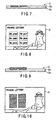
- FIGS. 7 and 8 show one example of the card C printed based on the character information.
- FIG. 7 shows a cross-sectional view of the card C on which the character information is thermally printed, while, on the other hand, FIG. 8 shows the above-mentioned heat-sensitive areas defined by six areas indicated by the broken line.
- the card C with the character information printed therein is conveyed on the card conveying path 7 and sent to a nip between the thermal head 12b and the platen roller 11b in the printing mechanism 10b.
- the heat generating elements of the thermal head 12b are selectively heat-generated based on the concealing position information to allow the thermal transfer ribbon 15 for concealment which is interposed between the thermal head 12b and the platen roller 11b to be melted and allow an ink from the thermal transfer ribbon 15 to be transferred to the card C (thermal transfer control means).
- the printing energy involved upon the making of printing by the thermal head 12b is based on the printing energy corresponding to the temperature detected by the temperature detecting sensor 29.
- FIGS. 9 and 10 show one example of a card C in which, with the thermal transfer ribbon 15 for concealment, printing is made based on the concealing position information.
- FIG. 9 is a cross-sectional view showing the card C in which the character information printed section is concealed, while, on the other hand, FIG. 10 shows a printed surface of the card C where printing is made with the thermal transfer ribbon for concealment.
- the next card which is set on the sheet supply device 3 starts its printing.
- cards C are taken one by one from the sheet supply device 3 so as to effect sequential printing. That is, onto the background-printed card C set to the sheet supply device 3 by the operator, character information set by the operator on the computer device is printed by the scratch card printer 1.
- the character information such as a character and image is thermally printed to a card position desired by the operator and the scratch cards concealed on their heat-sensitive printing area with a concealing material by the thermal transfer ribbon can be easily prepared in any numbers desired by the operator.
- the scratch card printer 1 of this embodiment two printing mechanisms 10a, 10b are provided and cards C set in the sheet supply device 3 are taken out one by one, printing information is printed by the printing mechanism 10a and printing is made by the printing mechanism 10b to conceal the character information with the thermal transfer ribbon and, by doing so, it is possible to easily prepare a scratch card. Since, therefore, it is not necessary to separately prepare a printer for character information printing and a printer for concealing the character information, it is possible to install the printer in a smaller space at a lower cost. Further, the operator can print any desired character information and prepare the character information-concealed scratch card in any desired numbers. It is, therefore, possible to provide a scratch card printer suitable to the production of many kinds of scratch cards in small numbers.
- the printing mechanism 10a prints the card C by a thermal printing with a thermal head 12a and, in comparison with the printing energy for thermally printing the character information on the card C by the thermal head 12a of the printing mechanism 10a, the printing energy for effecting printing by means of the thermal head 12b of the printing head 10b to conceal the character information on the card C is made smaller at all times. By doing so, it is possible to prevent a drop in printing quality which might otherwise be caused due to the card C being again color-developed. It is thus possible to prepare a scratch card of better printing quality.
- the CPU 19 Based on the data stored in the ROM 21 and temperature detected by the temperature detecting sensor 29, the CPU 19 separately controls the printing energy for thermally printing the character information on the card C by the thermal head 12a of the printing mechanism 12a and the printing energy for transferring the ink onto the card C so as to conceal the character information thermally printed on the card C by the thermal head 12b of the printing mechanism 10b, so that printing can be made at all times with an optimal printing energy to a varying ambient temperature.
- the thermal printing has been explained as being made by the thermal head (printing mechanism 10a) with the base material of the card as an underlying heat-sensitive sheet
- the present invention is not restricted thereto.
- Another structure may be used in which, for example, an ink ribbon for printing the character information is located between the thermal head 12a and the platen roller 11a and one end of the ink ribbon is supported on the frame 16 and retained on the supply shaft and the ink ribbon is wound by the take-up shaft. In this way, printing is made with the ink ribbon. Since, though being dependent upon the kinds of ink ribbons, printed character information using some ink ribbon is hard to erase when its concealing cover is scratched off the card surface, this structure is effective when using such a ribbon.
- FIGS. 1 to 4 and 11 to 17 an explanation of a comparable example will be made below. Since the structure of FIGS. 1 to 4 has already been explained, any detailed explanation of it is omitted here.
- a thermal transfer ribbon 15 for concealment is located between a thermal head 12b and a platen roller 11b.
- an ink of the thermal transfer ribbon 15 is melted or sublimed to allow printing to be made on a card C.
- An available thermal transfer ribbon 15 for concealment is retained on a supply shaft 17 having one end supported on the frame 16.
- the used thermal transfer ribbon portion is wound around a take-up shaft 18 having one end supported on the frame 16.
- the take-up shaft 18 is rotationally driven by a drive force transmitted from a stepping motor Mb through a gear train.
- a separating guide roller R is provided a predetermined distance on a downstream side from a location where the above-mentioned thermal head 12b is pushed against the platen roller 11b, so that a timing for separating the thermal transfer ribbon 15 for concealment from the card C is delayed (separating means). The delaying of the timing is because, after the transferred ink has been set, the thermal transfer ribbon 15 is separated from the card.
- the location of the separating guide roller R is initially set to be optimal based on the material, etc., of the thermal transfer ribbon 15.
- the separation guide roller R is provided, a structure using a shaft instead may also be adopted.
- FIG. 12 is a view showing a relation between the viscosity and the temperature when printing is made with the use of a thermal printing ribbon 15 for concealment, that is, a view showing the viscoelasticity characteristic of a material used for the inking layer of the thermal transfer ribbon 15 for concealment. Since a metal material is contained in the ink layer, as shown in FIG. 12 , the viscosity curve shows a gradual characteristic with respect to the temperature. Since the card C has its character information concealed with the material having such viscoelastic characteristic, if any printing is made as solid printing on a whole rectangular area P for example with an equal printing energy, no sharp printed edge will be obtained as shown in FIG. 13 . This ill-defined printed edge as indicated by an area P0 occurs, at a printing end of the card C, as a bleeding, a blurring or a reverse transfer.
- the following printing processing is done upon the making of printing by the thermal head 12b.
- the processing is done by running a control program stored in the ROM 21, another CPU may be provided as a dedicated one for implementing such a control program for the processing or a circuit section for performing such processing may be provided by implementing such circuit.
- the processing is started. First, the setting of the printing energy of the thermal head 12b is corrected based on the temperature detected by the sensor 29 (ST1). That is, the printing energy suitable to the ambient temperature is set based on the fixed data showing a temperature table stored in the ROM 21. Then, a parameter M1 representing the number of lines in a page is set to 1 (ST2). The received printing information is converted to image information and the data of an M line is read from the image memory 32 (ST3).
- the dots involved are so set as to be printed with a lower energy and so stored (ST8). If even one of these decisions at steps ST5 to ST7 is decided as being NO, the dots involved are so set as to be printed with a higher energy and so stored (ST9).
- the lower energy represented as the printing energy of the dots when printing is made means the printing energy set at step ST1 and the higher energy means an energy higher by about 15% than the printing energy set at step 1.
- the numeric value stored to the parameter N coincides with a total number of dots of the head. If it is decided that the numeric value stored to the parameter N does not coincide with the total number of dots of the head, 1 is added to the parameter N (ST11) and the process goes back to step ST5.
- the respective dots in the line set to the parameter M are turned ON with the set energy (ST12). That is, the parameter N is used to decide whether or not the printing energy of all dots of one line in a main scanning direction, that is, a direction in which printing is done by the thermal head 12b, is set.
- step ST13 it is decided that the numeric value set to the parameter M coincides with all the lines in one page. If it is decided that the numeric value set to the parameter M does not coincide with the number of all the lines in one page, 1 is added to the parameter M (step ST14) and the process goes back to step ST3. If it is decided that the numeric value set to the parameter M coincides with the number of all the lines in one page, the process is ended. That is, parameter M is used to decide whether or not the printing line of one page is ended.
- FIG. 15 is a view showing a difference in the printing energy involved at a solid printing area in the case where, in order to conceal character information by the use of the thermal transfer ribbon 15 for concealment, solid printing is done in the printing processing on, for example, a rectangular solid printing area. As shown in FIG. 15 , the printing energy of an outer marginal contour portion P1 of a solid printing area P is made greater than that of a remaining inside portion P2 of the solid printing area P.
- the operator sets, in a sheet supply device 3, a predetermined number of cards C having a heat-sensitive area set to allow character information to be thermally sensitized against its background design.
- This card C has, for example, six heat-sensitive areas where two 6th-prize and four "no points" are allowed to be thermally printed thereon.
- the operator prepares printing information containing character information for allowing the "6th-prize” and "no point” characters to be thermally printed on the six heat-sensitive areas, concealing position information for designating those concealing portions for concealing the character information to be printed on the six heat-sensitive areas, and sheet number information, etc., relating to the number of cards to be printed, and transmits the printing information through the I/F 31 to the scratch card printer 1.
- the printing information is received from the computer through the I/F 31, the operation/display section may be provided on the scratch card printer 1 in which case the printing information is prepared on the scratch card printer 1 by operating the operation/display section.
- the printing information is received through the I/F 31, one card is drawn from the sheet supply device 3 onto the card conveying path 7 to allow it to be conveyed between the thermal head 12a and the platen roller 11a in the printing mechanism 10a.
- the heat generating elements of the thermal head 12a are selectively heated based on the character information and a heat-sensitive sheet color-developing layer Cb is color-developed to allow the card to be thermally printed (printing control means).
- printing is done by the thermal head 12a with the printing energy corresponding to the thermal energy based on the temperature detecting sensor 29.
- the card C having its character information printed thereon is conveyed on the card conveying path 7 and then to a nip between the thermal head 12b and the platen roller 11b in the printing mechanism 10b.
- the heat generating elements of the thermal head 12b are selectively heated based on the concealing position information and above-mentioned printing processing to allow the thermal transfer ribbon 15 which is located between the thermal head 12b and the platen roller 11b to be melted and printing to be made on the card C with the thermal transfer ribbon 15 for concealment (thermal transfer printing control means).
- the printing energy when printing is made by the thermal head 12b is such that the printing energy involved at the outer marginal contour portion P1 of the six printing solid areas P is higher than the printing energy involved at a remaining inside area P2 of each of these six printing solid areas P.
- the separating guide roller R is provided and, without the thermal transfer ribbon being separated from the card C immediately after the thermal transfer ribbon ink has between thermally transferred by the thermal head, it is separated after the card is moved a predetermined position on the downstream side of the card conveying path 7.
- FIG. 16A is a view showing one example of a thus prepared scratch card having six rectangular printing areas P and FIG. 16B is a view showing a state of a scratch card in which, out of the six areas with character information printed thereon, one has its concealed cover scratched off the surface.
- the scratch card is prepared by making printing in a printing direction as indicated by an arrow in FIG. 16A . At the right-side portions of the six printed areas P with the character information concealed with a concealing cover on the scratch card, any bleeding, blurring and inverse transfer are not produced.
- printing is made with the printing mechanism 10b by heating the thermal transfer ribbon 15 by those associated heating elements of the thermal head 12b and, when such printing is done by making the printing energy at the outer marginal contour portion P1 of the respective printing area P greater than the printing energy at the remaining inside portion P2 of the printing area P, it is possible to prevent occurrence of bleeding, blurring, inverse transfer, etc., at the final printing end edge of the printing area P of the card C and thus to prepare a scratch card of better printing quality.
- the separation guide roller R is provided a predetermined distance on the downstream side from a location where the thermal head 12b is pressed against the platen roller 11b and, by doing so, the timing of separating the thermal transfer ribbon 15 from the card C is delayed. And without the thermal transfer ribbon 15 being separated from the card C immediately after the thermal transfer ribbon ink has been thermally transferred by the thermal head 12b, the ribbon is separated after the card C has been moved a predetermined position on the downstream side of the card conveying path, that is, after an ink from the ribbon has been fully set as a concealed cover on the card, it is possible to improve the printing quality.
- the printing energy at the outer marginal contour portion P1 of the solid printing area P is set to be greater than the printing energy at the remaining inside portion P2 of the solid printing area P
- the example is not restricted thereto. Since, as set out above, it is only necessary to prevent any ill-defined printing edge from being left at a final end edge portion of any printing area P upon the making of any solid printing, any structure may be adopted in which, as set out above, the printing energy at least at the final printing end edge portion P3 of any printing area P of the card C is set to be greater than the printing energy at the remaining portion P4 of the printing area P upon the making of solid as shown in FIG. 17 .
- the present invention is not restricted to the above-mentioned embodiment as it is and its constituent elements are variously embodied without departing from the essence of the present invention as defined in the appended claims.
- the present invention can be changed or modified by variously combining together a plurality of constituent parts disclosed in the above-mentioned embodiment.
Claims (5)
- Imprimante pour carte à gratter, comportant :une section de transport (8, 9, 14) qui transporte une carte ;un premier mécanisme d'impression (10a) qui possède une première tête thermique (12a) ;une section de contrôle d'impression qui contrôle la première tête thermique (12a) du premier mécanisme d'impression (10a), amenant la première tête thermique (12a) à effectuer une impression thermique pour imprimer une information sur la carte ;un second mécanisme d'impression (10b) qui est situé en aval du premier mécanisme d'impression (10a), dans une direction de transport de la carte par le moyen de transport (8, 9, 14), et qui possède une seconde tête thermique (12b) ; etune section de contrôle de transfert thermique qui contrôle la seconde tête thermique (12b) du second mécanisme d'impression (10b), amenant la seconde tête thermique (12b) à transférer l'encre depuis un ruban de transfert thermique (15) sur la carte, pour masquer ainsi l'information imprimée sur la carte par le premier mécanisme d'impression (10a) ;caractérisée par la seconde tête thermique (12b) du second mécanisme d'impression (10b) possédant une énergie d'impression inférieure à la première tête d'impression (12a) du premier mécanisme d'impression (10a) ;
et par ce qu'elle comporte en outre :une section de détection de température (29) qui détecte la température ambiante ; etune section de stockage (21) qui mémorise les niveaux d'énergie d'impression des têtes thermiques (12a, 12b) des premier (10a) et second (10b) mécanismes d'impression par rapport à la température ambiante,dans laquelle la section de contrôle d'impression et la section de contrôle de transfert thermique trouvent à partir de la section de stockage (21), l'énergie d'impression des têtes thermiques respectives correspondant à la température ambiante détectée par la section de détection de température et contrôlent l'énergie d'impression des têtes thermiques. - Imprimante pour carte à gratter selon la revendication 1, comportant en outre :une section de séparation (R) configurée pour retarder une synchronisation pendant laquelle le ruban de transfert thermique pour le masquage est séparé de la carte.
- Imprimante pour carte à gratter selon l'une des revendications 1 et 2, caractérisée en ce que la carte est configurée pour avoir un matériau de base de feuille thermosensible Ca et une couche de développement de couleur thermosensible Cb formée sur le matériau de base de feuille thermosensible.
- Imprimante pour carte à gratter selon une revendication 1 à 3, comportant en outre :un dispositif de délivrance de feuilles (3) qui supporte les cartes ; etun orifice de délivrance (6) qui délivre les cartes.
- Procédé d'impression d'information sur une carte à gratter, comportant les étapes consistant à :contrôler une tête d'impression (12a), amenant la tête d'impression à imprimer une information sur la carte transportée, ladite tête d'impression (12a) étant une première tête thermique ; etcontrôler une seconde tête thermique (12b), amenant la seconde tête thermique à transférer de l'encre à partir d'un ruban de transfert thermique (15) sur la carte, pour ainsi masquer l'information imprimée, sous la forme de caractères, sur la carte par la tête d'impression (12a), ladite seconde tête thermique (12b) étant située en aval de la tête d'impression, en direction du transport de la carte par le moyen de transport (8, 9, 14),caractérisé par la seconde tête thermique (12b) possédant une énergie d'impression plus faible que la tête d'impression (12a) et les niveaux d'énergie d'impression de la tête d'impression (12a) et de la seconde tête thermique (12b) étant contrôlés par rapport à une température ambiante mesurée.
Priority Applications (1)
| Application Number | Priority Date | Filing Date | Title |
|---|---|---|---|
| EP06015998A EP1726451A3 (fr) | 2003-08-08 | 2004-08-04 | Imprimante pour carte à gratter et méthode d'impression d'information sur une carte a gratter |
Applications Claiming Priority (4)
| Application Number | Priority Date | Filing Date | Title |
|---|---|---|---|
| JP2003290243 | 2003-08-08 | ||
| JP2003290243A JP2005059290A (ja) | 2003-08-08 | 2003-08-08 | スクラッチカードプリンタ |
| JP2003290244 | 2003-08-08 | ||
| JP2003290244A JP2005059291A (ja) | 2003-08-08 | 2003-08-08 | スクラッチカードプリンタ |
Related Child Applications (1)
| Application Number | Title | Priority Date | Filing Date |
|---|---|---|---|
| EP06015998A Division EP1726451A3 (fr) | 2003-08-08 | 2004-08-04 | Imprimante pour carte à gratter et méthode d'impression d'information sur une carte a gratter |
Publications (4)
| Publication Number | Publication Date |
|---|---|
| EP1504924A2 EP1504924A2 (fr) | 2005-02-09 |
| EP1504924A3 EP1504924A3 (fr) | 2005-04-27 |
| EP1504924B1 EP1504924B1 (fr) | 2008-10-01 |
| EP1504924B9 true EP1504924B9 (fr) | 2009-03-18 |
Family
ID=33554538
Family Applications (2)
| Application Number | Title | Priority Date | Filing Date |
|---|---|---|---|
| EP04018481A Expired - Fee Related EP1504924B9 (fr) | 2003-08-08 | 2004-08-04 | Imprimante pour carte à gratter et méthode d'impression d'information sur une carte a gratter |
| EP06015998A Withdrawn EP1726451A3 (fr) | 2003-08-08 | 2004-08-04 | Imprimante pour carte à gratter et méthode d'impression d'information sur une carte a gratter |
Family Applications After (1)
| Application Number | Title | Priority Date | Filing Date |
|---|---|---|---|
| EP06015998A Withdrawn EP1726451A3 (fr) | 2003-08-08 | 2004-08-04 | Imprimante pour carte à gratter et méthode d'impression d'information sur une carte a gratter |
Country Status (5)
| Country | Link |
|---|---|
| US (1) | US7052193B2 (fr) |
| EP (2) | EP1504924B9 (fr) |
| CN (1) | CN100355576C (fr) |
| DE (1) | DE602004016798D1 (fr) |
| ES (1) | ES2315597T3 (fr) |
Families Citing this family (5)
| Publication number | Priority date | Publication date | Assignee | Title |
|---|---|---|---|---|
| KR101019102B1 (ko) | 2010-07-05 | 2011-03-07 | 상림문화주식회사 | 플렉소그래피 결합형 오프셋 인쇄장치 |
| CN103660600B (zh) * | 2013-12-05 | 2015-12-02 | 北京亿赫伟信科技发展有限公司 | 热转印标识打印机 |
| JP6287930B2 (ja) * | 2015-03-31 | 2018-03-07 | ブラザー工業株式会社 | 印刷装置 |
| DE102018210836A1 (de) * | 2017-08-08 | 2019-02-14 | Heidelberger Druckmaschinen Ag | Vorrichtung zum Bedrucken und Trocknen von Bedruckstoff |
| CN114229144B (zh) * | 2021-12-31 | 2023-07-18 | 中体彩印务技术有限公司 | 一种即开型彩票的自动化生产方法及其系统 |
Family Cites Families (12)
| Publication number | Priority date | Publication date | Assignee | Title |
|---|---|---|---|---|
| US4643454A (en) * | 1986-01-14 | 1987-02-17 | Astro-Med, Inc. | Lottery ticket |
| US4850618A (en) * | 1986-05-13 | 1989-07-25 | Halladay Incorporated | Lottery ticket |
| SE9303860D0 (sv) | 1993-11-22 | 1993-11-22 | Markpoint Printer Ab | Information carrier for permanent information |
| GB9511499D0 (en) * | 1995-06-07 | 1995-08-02 | Babn Technologies Corp | 4-Colour process security overprinting of scratchable instant lottery tickets |
| TW362073B (en) * | 1996-03-15 | 1999-06-21 | Alps Electric Co Ltd | Method and apparatus for thermal transfer printing record |
| JP3305621B2 (ja) * | 1997-06-10 | 2002-07-24 | 大阪シーリング印刷株式会社 | 2色ラベルプリンタ |
| JPH11198554A (ja) * | 1998-01-13 | 1999-07-27 | Dainippon Printing Co Ltd | 熱転写受像シート及びその作成方法 |
| JP2000153623A (ja) * | 1998-11-20 | 2000-06-06 | Alps Electric Co Ltd | 熱転写プリンタにおける下地印刷処理方法 |
| JP2001113889A (ja) | 1999-10-21 | 2001-04-24 | Dainippon Printing Co Ltd | 熱転写シート |
| JP2002254833A (ja) * | 2001-02-28 | 2002-09-11 | Ricoh Co Ltd | 熱転写受像シート及びその製造方法 |
| JP2002254688A (ja) * | 2001-03-02 | 2002-09-11 | Noritsu Koki Co Ltd | 画像出力装置、インクリボン、および端末装置 |
| US6729656B2 (en) * | 2002-02-13 | 2004-05-04 | T.S.D. Llc | Debit card having applied personal identification number (PIN) and scratch-off coating and method of forming same |
-
2004
- 2004-08-04 ES ES04018481T patent/ES2315597T3/es active Active
- 2004-08-04 EP EP04018481A patent/EP1504924B9/fr not_active Expired - Fee Related
- 2004-08-04 EP EP06015998A patent/EP1726451A3/fr not_active Withdrawn
- 2004-08-04 US US10/911,779 patent/US7052193B2/en not_active Expired - Fee Related
- 2004-08-04 DE DE602004016798T patent/DE602004016798D1/de active Active
- 2004-08-06 CN CNB2004100981526A patent/CN100355576C/zh not_active Expired - Fee Related
Also Published As
| Publication number | Publication date |
|---|---|
| CN1607099A (zh) | 2005-04-20 |
| DE602004016798D1 (de) | 2008-11-13 |
| EP1726451A3 (fr) | 2008-03-05 |
| EP1504924A3 (fr) | 2005-04-27 |
| ES2315597T3 (es) | 2009-04-01 |
| US7052193B2 (en) | 2006-05-30 |
| EP1504924A2 (fr) | 2005-02-09 |
| CN100355576C (zh) | 2007-12-19 |
| EP1726451A2 (fr) | 2006-11-29 |
| US20050031394A1 (en) | 2005-02-10 |
| EP1504924B1 (fr) | 2008-10-01 |
Similar Documents
| Publication | Publication Date | Title |
|---|---|---|
| EP1955857B1 (fr) | Imprimante et procédé d'impression | |
| US7733361B2 (en) | Printer cartridge unifying thermal ribbon and transfer medium and thermal transfer printer employing the same | |
| US4772896A (en) | Booklet printing apparatus | |
| EP0580438B1 (fr) | Dispositif pour l'impression sur rubans | |
| EP1658989B1 (fr) | Imprimer de façon thermique | |
| US4647234A (en) | Thermal printer | |
| KR100284448B1 (ko) | 인쇄장치 | |
| JP2000296607A (ja) | インクジェットプリンタ | |
| GB2311040A (en) | Controlling printhead energy levels in a multi-colour thermal transfer printer | |
| JP2685635B2 (ja) | 熱転写プリンタの駆動制御方法 | |
| EP1504924B9 (fr) | Imprimante pour carte à gratter et méthode d'impression d'information sur une carte a gratter | |
| JP3723096B2 (ja) | 熱転写ラインプリンタ | |
| EP0899113B1 (fr) | Contrôle de densité d'impression dans une dispositif d'enregistrement thermique | |
| US5492061A (en) | Thermal printing method | |
| JP2005059290A (ja) | スクラッチカードプリンタ | |
| JPH05104710A (ja) | 記録装置 | |
| JP2000108390A (ja) | 熱転写プリンタ | |
| JP2005059291A (ja) | スクラッチカードプリンタ | |
| GB2139964A (en) | A printer | |
| KR0168281B1 (ko) | 열전사 프린터 | |
| EP0126627A1 (fr) | Une imprimante | |
| JPH0511035B2 (fr) | ||
| JP2003118156A (ja) | サーマルプリンタ | |
| JPH10100552A (ja) | 熱転写記録方法 | |
| JP2003200604A (ja) | 印字ヘッドの通電制御方法及びそれを用いたラインプリンタ |
Legal Events
| Date | Code | Title | Description |
|---|---|---|---|
| PUAI | Public reference made under article 153(3) epc to a published international application that has entered the european phase |
Free format text: ORIGINAL CODE: 0009012 |
|
| 17P | Request for examination filed |
Effective date: 20040804 |
|
| AK | Designated contracting states |
Kind code of ref document: A2 Designated state(s): AT BE BG CH CY CZ DE DK EE ES FI FR GB GR HU IE IT LI LU MC NL PL PT RO SE SI SK TR |
|
| AX | Request for extension of the european patent |
Extension state: AL HR LT LV MK |
|
| PUAL | Search report despatched |
Free format text: ORIGINAL CODE: 0009013 |
|
| AK | Designated contracting states |
Kind code of ref document: A3 Designated state(s): AT BE BG CH CY CZ DE DK EE ES FI FR GB GR HU IE IT LI LU MC NL PL PT RO SE SI SK TR |
|
| AX | Request for extension of the european patent |
Extension state: AL HR LT LV MK |
|
| AKX | Designation fees paid |
Designated state(s): BE DE ES FR GB NL |
|
| RAP1 | Party data changed (applicant data changed or rights of an application transferred) |
Owner name: TOSHIBA TEC KABUSHIKI KAISHA |
|
| GRAP | Despatch of communication of intention to grant a patent |
Free format text: ORIGINAL CODE: EPIDOSNIGR1 |
|
| GRAS | Grant fee paid |
Free format text: ORIGINAL CODE: EPIDOSNIGR3 |
|
| GRAA | (expected) grant |
Free format text: ORIGINAL CODE: 0009210 |
|
| AK | Designated contracting states |
Kind code of ref document: B1 Designated state(s): BE DE ES FR GB NL |
|
| REG | Reference to a national code |
Ref country code: GB Ref legal event code: FG4D |
|
| REF | Corresponds to: |
Ref document number: 602004016798 Country of ref document: DE Date of ref document: 20081113 Kind code of ref document: P |
|
| REG | Reference to a national code |
Ref country code: ES Ref legal event code: FG2A Ref document number: 2315597 Country of ref document: ES Kind code of ref document: T3 |
|
| PLBE | No opposition filed within time limit |
Free format text: ORIGINAL CODE: 0009261 |
|
| STAA | Information on the status of an ep patent application or granted ep patent |
Free format text: STATUS: NO OPPOSITION FILED WITHIN TIME LIMIT |
|
| 26N | No opposition filed |
Effective date: 20090702 |
|
| PGFP | Annual fee paid to national office [announced via postgrant information from national office to epo] |
Ref country code: FR Payment date: 20090814 Year of fee payment: 6 Ref country code: ES Payment date: 20090902 Year of fee payment: 6 |
|
| PGFP | Annual fee paid to national office [announced via postgrant information from national office to epo] |
Ref country code: NL Payment date: 20090803 Year of fee payment: 6 Ref country code: GB Payment date: 20090729 Year of fee payment: 6 Ref country code: DE Payment date: 20090730 Year of fee payment: 6 |
|
| PGFP | Annual fee paid to national office [announced via postgrant information from national office to epo] |
Ref country code: BE Payment date: 20090825 Year of fee payment: 6 |
|
| BERE | Be: lapsed |
Owner name: TOSHIBA TEC K.K. Effective date: 20100831 |
|
| REG | Reference to a national code |
Ref country code: NL Ref legal event code: V1 Effective date: 20110301 |
|
| GBPC | Gb: european patent ceased through non-payment of renewal fee |
Effective date: 20100804 |
|
| REG | Reference to a national code |
Ref country code: FR Ref legal event code: ST Effective date: 20110502 |
|
| PG25 | Lapsed in a contracting state [announced via postgrant information from national office to epo] |
Ref country code: NL Free format text: LAPSE BECAUSE OF NON-PAYMENT OF DUE FEES Effective date: 20110301 |
|
| REG | Reference to a national code |
Ref country code: DE Ref legal event code: R119 Ref document number: 602004016798 Country of ref document: DE Effective date: 20110301 |
|
| PG25 | Lapsed in a contracting state [announced via postgrant information from national office to epo] |
Ref country code: FR Free format text: LAPSE BECAUSE OF NON-PAYMENT OF DUE FEES Effective date: 20100831 Ref country code: BE Free format text: LAPSE BECAUSE OF NON-PAYMENT OF DUE FEES Effective date: 20100831 Ref country code: DE Free format text: LAPSE BECAUSE OF NON-PAYMENT OF DUE FEES Effective date: 20110301 |
|
| PG25 | Lapsed in a contracting state [announced via postgrant information from national office to epo] |
Ref country code: GB Free format text: LAPSE BECAUSE OF NON-PAYMENT OF DUE FEES Effective date: 20100804 |
|
| REG | Reference to a national code |
Ref country code: ES Ref legal event code: FD2A Effective date: 20111019 |
|
| PG25 | Lapsed in a contracting state [announced via postgrant information from national office to epo] |
Ref country code: ES Free format text: LAPSE BECAUSE OF NON-PAYMENT OF DUE FEES Effective date: 20100805 |