EP1504875B1 - Austauschbares Walzenteil - Google Patents
Austauschbares Walzenteil Download PDFInfo
- Publication number
- EP1504875B1 EP1504875B1 EP04102843A EP04102843A EP1504875B1 EP 1504875 B1 EP1504875 B1 EP 1504875B1 EP 04102843 A EP04102843 A EP 04102843A EP 04102843 A EP04102843 A EP 04102843A EP 1504875 B1 EP1504875 B1 EP 1504875B1
- Authority
- EP
- European Patent Office
- Prior art keywords
- roller
- planetary gear
- roller part
- extruder according
- connecting ring
- Prior art date
- Legal status (The legal status is an assumption and is not a legal conclusion. Google has not performed a legal analysis and makes no representation as to the accuracy of the status listed.)
- Expired - Lifetime
Links
- 238000001125 extrusion Methods 0.000 claims abstract description 7
- 238000010438 heat treatment Methods 0.000 claims abstract description 7
- 238000005496 tempering Methods 0.000 claims description 3
- 238000007872 degassing Methods 0.000 description 3
- 238000000034 method Methods 0.000 description 2
- XLYOFNOQVPJJNP-UHFFFAOYSA-N water Substances O XLYOFNOQVPJJNP-UHFFFAOYSA-N 0.000 description 2
- 101000983325 Drosophila melanogaster Intraflagellar transport protein 172 homolog Proteins 0.000 description 1
- 230000002146 bilateral effect Effects 0.000 description 1
- 239000003086 colorant Substances 0.000 description 1
- 238000001816 cooling Methods 0.000 description 1
- 238000002347 injection Methods 0.000 description 1
- 239000007924 injection Substances 0.000 description 1
- 238000009434 installation Methods 0.000 description 1
- 239000000463 material Substances 0.000 description 1
- 239000000155 melt Substances 0.000 description 1
- 238000013021 overheating Methods 0.000 description 1
- 238000005096 rolling process Methods 0.000 description 1
- 239000000243 solution Substances 0.000 description 1
Images
Classifications
-
- B—PERFORMING OPERATIONS; TRANSPORTING
- B29—WORKING OF PLASTICS; WORKING OF SUBSTANCES IN A PLASTIC STATE IN GENERAL
- B29C—SHAPING OR JOINING OF PLASTICS; SHAPING OF MATERIAL IN A PLASTIC STATE, NOT OTHERWISE PROVIDED FOR; AFTER-TREATMENT OF THE SHAPED PRODUCTS, e.g. REPAIRING
- B29C48/00—Extrusion moulding, i.e. expressing the moulding material through a die or nozzle which imparts the desired form; Apparatus therefor
- B29C48/25—Component parts, details or accessories; Auxiliary operations
- B29C48/78—Thermal treatment of the extrusion moulding material or of preformed parts or layers, e.g. by heating or cooling
- B29C48/80—Thermal treatment of the extrusion moulding material or of preformed parts or layers, e.g. by heating or cooling at the plasticising zone, e.g. by heating cylinders
- B29C48/83—Heating or cooling the cylinders
- B29C48/834—Cooling
-
- B—PERFORMING OPERATIONS; TRANSPORTING
- B29—WORKING OF PLASTICS; WORKING OF SUBSTANCES IN A PLASTIC STATE IN GENERAL
- B29C—SHAPING OR JOINING OF PLASTICS; SHAPING OF MATERIAL IN A PLASTIC STATE, NOT OTHERWISE PROVIDED FOR; AFTER-TREATMENT OF THE SHAPED PRODUCTS, e.g. REPAIRING
- B29C48/00—Extrusion moulding, i.e. expressing the moulding material through a die or nozzle which imparts the desired form; Apparatus therefor
- B29C48/25—Component parts, details or accessories; Auxiliary operations
- B29C48/36—Means for plasticising or homogenising the moulding material or forcing it through the nozzle or die
- B29C48/395—Means for plasticising or homogenising the moulding material or forcing it through the nozzle or die using screws surrounded by a cooperating barrel, e.g. single screw extruders
- B29C48/40—Means for plasticising or homogenising the moulding material or forcing it through the nozzle or die using screws surrounded by a cooperating barrel, e.g. single screw extruders using two or more parallel screws or at least two parallel non-intermeshing screws, e.g. twin screw extruders
- B29C48/435—Sub-screws
- B29C48/44—Planetary screws
-
- B—PERFORMING OPERATIONS; TRANSPORTING
- B29—WORKING OF PLASTICS; WORKING OF SUBSTANCES IN A PLASTIC STATE IN GENERAL
- B29C—SHAPING OR JOINING OF PLASTICS; SHAPING OF MATERIAL IN A PLASTIC STATE, NOT OTHERWISE PROVIDED FOR; AFTER-TREATMENT OF THE SHAPED PRODUCTS, e.g. REPAIRING
- B29C48/00—Extrusion moulding, i.e. expressing the moulding material through a die or nozzle which imparts the desired form; Apparatus therefor
- B29C48/25—Component parts, details or accessories; Auxiliary operations
- B29C48/78—Thermal treatment of the extrusion moulding material or of preformed parts or layers, e.g. by heating or cooling
- B29C48/80—Thermal treatment of the extrusion moulding material or of preformed parts or layers, e.g. by heating or cooling at the plasticising zone, e.g. by heating cylinders
- B29C48/83—Heating or cooling the cylinders
- B29C48/832—Heating
-
- B—PERFORMING OPERATIONS; TRANSPORTING
- B29—WORKING OF PLASTICS; WORKING OF SUBSTANCES IN A PLASTIC STATE IN GENERAL
- B29C—SHAPING OR JOINING OF PLASTICS; SHAPING OF MATERIAL IN A PLASTIC STATE, NOT OTHERWISE PROVIDED FOR; AFTER-TREATMENT OF THE SHAPED PRODUCTS, e.g. REPAIRING
- B29C48/00—Extrusion moulding, i.e. expressing the moulding material through a die or nozzle which imparts the desired form; Apparatus therefor
- B29C48/25—Component parts, details or accessories; Auxiliary operations
- B29C48/36—Means for plasticising or homogenising the moulding material or forcing it through the nozzle or die
- B29C48/50—Details of extruders
- B29C48/76—Venting, drying means; Degassing means
-
- B—PERFORMING OPERATIONS; TRANSPORTING
- B29—WORKING OF PLASTICS; WORKING OF SUBSTANCES IN A PLASTIC STATE IN GENERAL
- B29C—SHAPING OR JOINING OF PLASTICS; SHAPING OF MATERIAL IN A PLASTIC STATE, NOT OTHERWISE PROVIDED FOR; AFTER-TREATMENT OF THE SHAPED PRODUCTS, e.g. REPAIRING
- B29C48/00—Extrusion moulding, i.e. expressing the moulding material through a die or nozzle which imparts the desired form; Apparatus therefor
- B29C48/25—Component parts, details or accessories; Auxiliary operations
- B29C48/78—Thermal treatment of the extrusion moulding material or of preformed parts or layers, e.g. by heating or cooling
- B29C48/80—Thermal treatment of the extrusion moulding material or of preformed parts or layers, e.g. by heating or cooling at the plasticising zone, e.g. by heating cylinders
- B29C48/83—Heating or cooling the cylinders
-
- B—PERFORMING OPERATIONS; TRANSPORTING
- B29—WORKING OF PLASTICS; WORKING OF SUBSTANCES IN A PLASTIC STATE IN GENERAL
- B29C—SHAPING OR JOINING OF PLASTICS; SHAPING OF MATERIAL IN A PLASTIC STATE, NOT OTHERWISE PROVIDED FOR; AFTER-TREATMENT OF THE SHAPED PRODUCTS, e.g. REPAIRING
- B29C48/00—Extrusion moulding, i.e. expressing the moulding material through a die or nozzle which imparts the desired form; Apparatus therefor
- B29C48/25—Component parts, details or accessories; Auxiliary operations
- B29C48/78—Thermal treatment of the extrusion moulding material or of preformed parts or layers, e.g. by heating or cooling
- B29C48/80—Thermal treatment of the extrusion moulding material or of preformed parts or layers, e.g. by heating or cooling at the plasticising zone, e.g. by heating cylinders
- B29C48/84—Thermal treatment of the extrusion moulding material or of preformed parts or layers, e.g. by heating or cooling at the plasticising zone, e.g. by heating cylinders by heating or cooling the feeding screws
- B29C48/845—Heating
-
- B—PERFORMING OPERATIONS; TRANSPORTING
- B29—WORKING OF PLASTICS; WORKING OF SUBSTANCES IN A PLASTIC STATE IN GENERAL
- B29C—SHAPING OR JOINING OF PLASTICS; SHAPING OF MATERIAL IN A PLASTIC STATE, NOT OTHERWISE PROVIDED FOR; AFTER-TREATMENT OF THE SHAPED PRODUCTS, e.g. REPAIRING
- B29C48/00—Extrusion moulding, i.e. expressing the moulding material through a die or nozzle which imparts the desired form; Apparatus therefor
- B29C48/25—Component parts, details or accessories; Auxiliary operations
- B29C48/78—Thermal treatment of the extrusion moulding material or of preformed parts or layers, e.g. by heating or cooling
- B29C48/80—Thermal treatment of the extrusion moulding material or of preformed parts or layers, e.g. by heating or cooling at the plasticising zone, e.g. by heating cylinders
- B29C48/84—Thermal treatment of the extrusion moulding material or of preformed parts or layers, e.g. by heating or cooling at the plasticising zone, e.g. by heating cylinders by heating or cooling the feeding screws
- B29C48/85—Cooling
Definitions
- a planetary roller extruder having at least one roller part, wherein the roller part of an outer segment, an internally wound roller cylinder, a driven main spindle and a plurality of arranged around the main spindle planetary spindles is formed, wherein the roller part has bilateral terminal portions.
- the modularity does not refer to the fact that individual segments of a roller part are equipped with each other.
- roller parts are rotatable, that is, the inlet and outlet of each roller segment are designed the same. But this would ensure that assembly, handling and life extension are significantly improved.
- the object of the invention is to redesign the previous design or the underlying concept in order to ensure the absolute modularity.
- connection areas are symmetrical to each other about a right angle to the extrusion direction forming symmetry axis, wherein the connection areas are the contact surfaces on the front side of the roll cylinder.
- a closure ring is arranged, which in turn with respect to the roller part in the corresponding area has the same geometry as the connecting rings.
- the connecting rings can be varied in the inner diameter, so that the function of the known congestion or dispersing rings is made possible.
- the connecting rings also have the same width in various planetary roller extruder sizes so that even planetary spindles within various planetary roller extruder sizes will be interchangeable in the future.
- a planetary roller extruder with through planetary spindles can also be realized in split roll cylinders, in that the connecting ring in the inner diameter has the helical internal toothing typical for the planetary roller extruder.
- roller parts are designed in the outer region such that the external access to the connecting ring is possible. This ensures that the connecting rings can also be designed as combination rings. It is thus possible to ensure a degassing or colorant addition via the connecting rings.
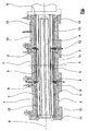
- each roller part 1 consists of an outer segment 2 and an internally toothed roller cylinder 3. All three roller parts 1 shown here have a common main spindle 4. In each roller part 1 planetary spindles 5 are arranged around the main spindle 4, shown here only in the middle part of the roller. Each roller part has a region 6, on which the connecting ring 9 comes to rest. This area 6 of each roller part is symmetrical about the symmetry axis 7, wherein the axis of symmetry 7 is perpendicular to the extrusion direction 8. It is thus possible to replace the roller part 1 completely or, for example, to change only the roll cylinder 3.
- the mounting position is irrelevant, since the connection geometry is identical to the connecting ring 9 in each point.
- the first roller part can be exchanged, for example, by the third roller part, because the connection dimensions are in the region 6 of the roller part suitable for the end ring 11.
- pins 12 are arranged, which can serve for example for degassing or damming the melt.
- a heating element 10 On the first roller part is a heating element 10 by way of example arranged. This makes it possible to influence the temperature control 13, which is shown here as a water cycle.
- the heating element 10 it is conceivable to heat the roller part 1 by means of the heating element 10 and to rapidly cool the roller part 1 when the temperature is too high by means of the water circuit 13 in order to prevent overheating of the material.
- the heating elements 10 it is also conceivable to attach the heating elements 10 to the other roller parts 1.
- the heating element 10 is also connected via the illustrated connection elements with the machine control in connection, whereby an exact temperature control is made possible.
- the invention described and exemplified in the figure combines all the possibilities of a modern planetary roller extruder system.
- the planetary roller system is of absolutely modular design, the individual roller parts are rotatable and exchangeable and the heating elements allow improved temperature control.
Landscapes
- Engineering & Computer Science (AREA)
- Mechanical Engineering (AREA)
- Physics & Mathematics (AREA)
- Thermal Sciences (AREA)
- Extrusion Moulding Of Plastics Or The Like (AREA)
- Massaging Devices (AREA)
- Harvester Elements (AREA)
Description
- Planetwalzenextruder mit mindestens einem Walzenteil, wobei das Walzenteil aus einem Außensegment, einem innenverzahnten Walzenzylinder, einer angetriebenen Hauptspindel sowie mehreren um die Hauptspindel angeordneten Planetspindeln gebildet wird, wobei das Walzenteil beidseitige Anschlußbereiche aufweist.
- Bekannt sind für das System Planetwalzenextruder (PWE) in sogenannter modularer Ausführung, wobei die Modularität sich darauf bezieht, daß Walzenteile bei der Konzeption bzw. Auslegung mit unterschiedlicher Walzenteillänge, geteilt oder ungeteilt, mit Möglichkeiten der Entgasung oder Einspritzung und anderen Prozessvarianten ausgestattet werden. Ein Beispiel für einen derartig aufgebauten Extruder mit mehreren Planetwalzenteilen zeigt die
DE-A-25 21 774 . - Die Modularität bezieht sich dabei aber nicht darauf, daß einzelne Segmente eines Walzenteils untereinander ausgestattet sind. Besonders auch nicht darauf, daß Walzenteile drehbar sind, das heißt, daß der Einlauf und Auslauf eines jeden Walzenteilsegments gleich gestaltet sind. Dies würde aber sicherstellen, daß Montage, Handhabung und Lebenszeitverlängerung wesentlich verbessert werden.
- Der wesentliche Nachteil der oben beschriebenen Ausführung ist, daß die bisher bekannten und ausgeführten Walzenteile nicht kompatibel sind. Das heißt, daß insbesondere nach der Konzeption bzw. Auslegung die einzelnen Teile des Walzenteils untereinander nicht tauschbar ausgeführt sind. Wünschenswert wäre aber, daß einzelne Segmente besonders bei wechselnder Verfahrensaufgabe oder unterschiedlich fortgeschrittenem Verschleiß von einzelnen Segmenten absolut austauschbar wären. Vorteile würden sich zudem für die Montage ergeben, indem Teile nicht mehr seitenverkehrt montiert werden können.
- Die Aufgabe der Erfindung ist es, die bisherige Konstruktion bzw. das dahinterstehende Konzept derart umzugestalten, um die absolute Modularität sicherzustellen.
- Die Lösung der Aufgabe ist in Verbindung mit dem Oberbegriff des Anspruches 1 dadurch gekennzeichnet, daß die Anschlussbereiche zueinander um eine einen rechten Winkel zur Extrusionsrichtung bildende Symmetrieachse symmetrisch sind, wobei die Anschlussbereiche die Kontaktflächen an der Stirnseite des Walzenzylinders sind.
- Dies führt insbesondere auch zu einer absoluten Freiheit bei der Zusammenstellung von Einzelkomponenten und deren Positionierung im Verlauf des Walzenteils.
- Mehrere solcher Elemente können mittels eines Verbindungsringes verbunden werden. Auch diese Verbindungsringe sind wiederum gleich aufgebaut, so daß eine falsche Einbaulage verhindert wird.
- Am Ende in Extrusionsrichtung betrachtet ist ein Abschlußring angeordnet, der wiederum in Bezug auf das Walzenteil im entsprechenden Bereich die gleiche Geometrie aufweist, wie die Verbindungsringe.
- Die Verbindungsringe können im Innendurchmesser variiert werden, so daß die Funktion der bekannten Stau- oder Dispergierringe ermöglicht wird. Die Verbindungsringe weisen auch bei verschiedenen Planetwalzenextruderbaugrößen die gleiche Breite auf, so daß auch Planetspindeln innerhalb verschiedener Planetwalzenextruderbaugrößen in Zukunft austauschbar sind. Ein Planetwalzenextruder mit durchgehenden Planetspindeln kann auch bei geteilten Walzenzylindern realisiert werden, indem der Verbindungsring im Innendurchmesser die für die Planetwalzenextruder typische schräg verzahnte Innenverzahnung aufweist.
- Die Walzenteile sind im äußeren Bereich derart gestaltet, daß der äußerliche Zugang zum Verbindungsring möglich wird. Damit ist sichergestellt, daß die Verbindungsringe auch als Kombinationsringe ausgeführt werden können. Es ist somit möglich, über die Verbindungsringe eine Entgasung oder auch eine Farbmittelzugabe zu gewährleisten.
- In der Zeichnung ist schematisch ein Beispiel dargestellt, es zeigt die Figur einen Planetwalzenextruder mit mehreren Walzenteilen 1, die über Verbindungsringe 9 zusammengesetzt sind. Jedes Walzenteil 1 besteht aus einem Außensegment 2 und einem innenverzahnten Walzenzylinder 3. Alle drei hier dargestellten Walzenteile 1 haben eine gemeinsame Hauptspindel 4. In jedem Walzenteil 1 sind um die Hauptspindel 4 Planetspindeln 5 angeordnet, hier nur im mittleren Walzenteil dargestellt. Jedes Walzenteil weist einen Bereich 6 auf, an dem der Verbindungsring 9 zur Anlage kommt. Dieser Bereich 6 jeden Walzenteiles ist über die Symmetrieachse 7 symmetrisch, wobei die Symmetrieachse 7 rechtwinklig zur Extrusionsrichtung 8 ist. Es ist somit möglich, das Walzenteil 1 komplett auszutauschen oder beispielsweise nur den Walzenzylinder 3 zu wechseln. Durch den symmetrischen Bereich 6 ist die Einbaulage irrelevant, da die Anschlußgeometrie zu dem Verbindungsring 9 in jedem Punkt identisch ist. Somit ist selbst die Position, sprich die Lage eines Walzenteils in Extrusionsrichtung variabel. Das erste Walzenteil kann beispielsweise durch das dritte Walzenteil getauscht werden, denn auch die Anschlußmaße sind im Bereich 6 des Walzenteils passend zum Abschlußring 11. In den Verbindungsringen 9 sind Stifte 12 angeordnet, die beispielsweise zur Entgasung oder zum Aufstauen der Schmelze dienen können. Am ersten Walzenteil ist beispielhaft ein Heizelement 10 angeordnet. Hiermit wird es möglich, die Temperierung 13, die hier als Wasserkreislauf dargestellt ist, zu beeinflussen. Es ist zum Beispiel denkbar, mittels des Heizelementes 10 das Walzenteil 1 zu erwärmen und bei Auftreten einer zu hohen Temperatur mittels des Wasserkreislaufs 13 das Walzenteil 1 schnell zu kühlen, um eine Überhitzung des Materials zu verhindern. Selbstverständlich ist es auch denkbar, die Heizelemente 10 an den anderen Walzenteilen 1 anzubringen. Das Heizelement 10 steht auch über die dargestellten Anschlußelemente mit der Maschinensteuerung in Verbindung, wodurch eine exakte Temperaturregelung ermöglicht wird.
- Die beschriebene und in der Figur beispielhaft dargestellte Erfindung verbindet alle Möglichkeiten eines modernen Planetwalzenextrudersystems. Das Planetwalzensystem ist absolut modular aufgebaut, die einzelnen Walzenteile sind dreh- und austauschbar und mittels der Heizelemente ist eine verbesserte Temperaturführung möglich.
-
- 1
- Walzenteil
- 2
- Außensegment
- 3
- Walzenzylinder
- 4
- Hauptspindel
- 5
- Planetenspindel
- 6
- symmetrischer Bereich an 1
- 7
- Symmetrieachse
- 8
- Extrusionsrichtung
- 9
- Verbindungsring
- 10
- Temperierelement
- 11
- Abschlußring
- 12
- Stift
- 13
- Kühlkreislauf
Claims (7)
- Planetwalzenextruder mit mindestens einem Walzenteil (1), wobei
das Walzenteil (1) aus einem Außensegment (2),
einem innenverzahnten Walzenzylinder (3),
einer angetriebenen Hauptspindel (4) sowie mehreren um die Hauptspindel (3) angeordneten Planetspindeln (5) gebildet wird,
wobei das Walzenteil (1) beidseitig Anschlußbereiche (6) aufweist,
dadurch gekennzeichnet, dass
die Anschlussbereiche (6) zueinander um eine einen rechten Winkel zur Extrusionsrichtung (8) bildende Symmetrieachse (7) symmetrisch sind,
wobei die Anschlussbereiche (6) die Kontaktflächen an der Stirnseite des Walzenzylinders (3) sind. - Planetwalzenextruder nach Anspruch 1, dadurch gekennzeichnet, dass mehrere Walzenteile (1) mittels eines Verbindungsringes (9) verbindbar sind.
- Planetwalzenextruder nach Anspruch 2, dadurch gekennzeichnet, dass der Verbindungsring (9) im Anschlussbereich (6) am Walzenteil (1) anliegt.
- Planetwalzenextruder nach Anspruch 3, dadurch gekennzeichnet, dass der Verbindungsring (9) mit einer Innenverzahnung ausgeführt ist.
- Planetwalzenextruder nach Anspruch 3, dadurch gekennzeichnet, dass der Verbindungsring (9) als Kombinationsring ausgeführt ist.
- Planetwalzenextruder nach einem der vorigen Ansprüche, dadurch gekennzeichnet, dass mindestens ein Walzenteil (1) mit einem elektrisch steuer- oder regelbaren Temperierelement (10) versehen ist.
- Planetwalzenextruder nach Anspruch 6, dadurch gekennzeichnet, dass das Temperiermittel (10) ein Heizelement ist.
Applications Claiming Priority (4)
| Application Number | Priority Date | Filing Date | Title |
|---|---|---|---|
| DE10336371 | 2003-08-06 | ||
| DE10336371 | 2003-08-06 | ||
| DE10356356 | 2003-11-28 | ||
| DE10356356.3A DE10356356B4 (de) | 2003-08-06 | 2003-11-28 | Austauschbares Walzenteil |
Publications (2)
| Publication Number | Publication Date |
|---|---|
| EP1504875A1 EP1504875A1 (de) | 2005-02-09 |
| EP1504875B1 true EP1504875B1 (de) | 2007-12-12 |
Family
ID=33553485
Family Applications (1)
| Application Number | Title | Priority Date | Filing Date |
|---|---|---|---|
| EP04102843A Expired - Lifetime EP1504875B1 (de) | 2003-08-06 | 2004-06-21 | Austauschbares Walzenteil |
Country Status (3)
| Country | Link |
|---|---|
| EP (1) | EP1504875B1 (de) |
| AT (1) | ATE380647T1 (de) |
| DE (1) | DE502004005681D1 (de) |
Families Citing this family (1)
| Publication number | Priority date | Publication date | Assignee | Title |
|---|---|---|---|---|
| DE102013208445A1 (de) * | 2013-05-08 | 2014-11-13 | Tesa Se | Verfahren zum Herstellen einer syntaktisch geschäumten Polymermasse, vorzugsweise einer druckempfindlichen Klebemasse, Vorrichtung zur Durchführung des Verfahrens, Extrudat und Selbstklebeband |
Family Cites Families (7)
| Publication number | Priority date | Publication date | Assignee | Title |
|---|---|---|---|---|
| DE2158246C3 (de) * | 1971-11-24 | 1979-06-28 | Eickhoff-Kleinewefers Kunststoffmaschinen Gmbh, 4630 Bochum | Vorrichtung zum Aufbereiten und Strangpressen von thermoplastischen Kunststoffen |
| DE2521774A1 (de) * | 1975-05-16 | 1976-11-25 | Eickhoff Kleinewefers Kunststo | Vorrichtung zum aufbereiten und strangpressen von thermoplastischen kunststoffen |
| DE2905717A1 (de) * | 1979-02-15 | 1980-08-28 | Berstorff Gmbh Masch Hermann | Einschneckenextruder zum verarbeiten und strangpressen von thermoplastischen massen |
| DE2906324C2 (de) * | 1979-02-19 | 1982-06-24 | Hermann Berstorff Maschinenbau Gmbh, 3000 Hannover | Mehrstufige Vorrichtung zum Plastifizieren und Strangpressen von plastischen Massen |
| JPS60189416A (ja) * | 1984-03-09 | 1985-09-26 | Ishinaka Tekkosho:Kk | 押出機 |
| DE8911796U1 (de) * | 1989-02-24 | 1990-01-18 | Entex Rust & Mitschke Gmbh, 44805 Bochum | Extruder |
| DE29818525U1 (de) * | 1998-10-20 | 1999-01-28 | Battenfeld Extrusionstechnik Gmbh, 32547 Bad Oeynhausen | Vorrichtung zum Extrudieren von Kunststoffmaterial |
-
2004
- 2004-06-21 EP EP04102843A patent/EP1504875B1/de not_active Expired - Lifetime
- 2004-06-21 AT AT04102843T patent/ATE380647T1/de active
- 2004-06-21 DE DE502004005681T patent/DE502004005681D1/de not_active Expired - Lifetime
Also Published As
| Publication number | Publication date |
|---|---|
| DE502004005681D1 (de) | 2008-01-24 |
| ATE380647T1 (de) | 2007-12-15 |
| EP1504875A1 (de) | 2005-02-09 |
Similar Documents
| Publication | Publication Date | Title |
|---|---|---|
| DE69502550T2 (de) | Profilanpassung für Vielwalzengerüste | |
| EP0295319B1 (de) | Tiefdruckzylinder, bestehend aus einem Kern und einer lösbar mit diesem verbundenen Hülse | |
| DE2839552C3 (de) | Düsenkopf zum Herstellen von Kunststoffgranulat | |
| DE2027910B2 (de) | Vorrichtung zum Strangpressen oder Spritzgießen von Kunststoff | |
| DE2011777C3 (de) | ||
| EP4105506A1 (de) | Käfigsegment für einen rollenlagerkäfig | |
| EP0475084A1 (de) | Radial-Buchsenlager | |
| EP1631436B1 (de) | Kalibriereinrichtung | |
| DE2707907A1 (de) | Walze bzw. welle | |
| EP1504875B1 (de) | Austauschbares Walzenteil | |
| EP1157805B1 (de) | Kalibrierhülse für ein extrudiertes Kunststoffrohr | |
| DE10356356B4 (de) | Austauschbares Walzenteil | |
| EP3663043A1 (de) | Schleifwerkzeug | |
| DE10249762B4 (de) | Rollengewindetrieb | |
| EP2690926A1 (de) | Induktor | |
| DE102016201691A1 (de) | Flüssigkeitsgekühlte elektrische Maschine für ein Kraftfahrzeug | |
| DE19530430C1 (de) | Vorrichtung zum elektroinduktiven Härten von unmittelbar benachbart angeordneten Lagerflächen einer Kurbelwelle | |
| DD229072B1 (de) | Temperierbarer extruderzylinder, insbesondere fuer doppelschneckenextruder | |
| WO2023088732A1 (de) | Elektrische maschine, insbesondere elektrische maschine für ein kraftfahrzeug | |
| DE69403704T2 (de) | Strangpresse | |
| EP3161336B1 (de) | Planetenwälzlager | |
| DE102014202326B4 (de) | Planetensatz eines Planetenwälzgewindetriebes | |
| DE102011084231A1 (de) | Rollenlinie für eine Stranggießanlage sowie Verfahren zum Betrieb einer Rollenlinie | |
| EP3551898B1 (de) | Schaftanordnung mit fluidstauring | |
| DE2715762A1 (de) | Waelzschraubgetriebe mit aeusserem umlauf von waelzelementen |
Legal Events
| Date | Code | Title | Description |
|---|---|---|---|
| PUAI | Public reference made under article 153(3) epc to a published international application that has entered the european phase |
Free format text: ORIGINAL CODE: 0009012 |
|
| AK | Designated contracting states |
Kind code of ref document: A1 Designated state(s): AT BE BG CH CY CZ DE DK EE ES FI FR GB GR HU IE IT LI LU MC NL PL PT RO SE SI SK TR |
|
| AX | Request for extension of the european patent |
Extension state: AL HR LT LV MK |
|
| 17P | Request for examination filed |
Effective date: 20050222 |
|
| 17Q | First examination report despatched |
Effective date: 20050317 |
|
| AKX | Designation fees paid |
Designated state(s): AT DE FR GB IT TR |
|
| 17Q | First examination report despatched |
Effective date: 20050317 |
|
| GRAP | Despatch of communication of intention to grant a patent |
Free format text: ORIGINAL CODE: EPIDOSNIGR1 |
|
| GRAC | Information related to communication of intention to grant a patent modified |
Free format text: ORIGINAL CODE: EPIDOSCIGR1 |
|
| GRAS | Grant fee paid |
Free format text: ORIGINAL CODE: EPIDOSNIGR3 |
|
| GRAA | (expected) grant |
Free format text: ORIGINAL CODE: 0009210 |
|
| AK | Designated contracting states |
Kind code of ref document: B1 Designated state(s): AT DE FR GB IT TR |
|
| REG | Reference to a national code |
Ref country code: GB Ref legal event code: FG4D Free format text: NOT ENGLISH |
|
| REF | Corresponds to: |
Ref document number: 502004005681 Country of ref document: DE Date of ref document: 20080124 Kind code of ref document: P |
|
| GBT | Gb: translation of ep patent filed (gb section 77(6)(a)/1977) |
Effective date: 20080312 |
|
| ET | Fr: translation filed | ||
| PLBE | No opposition filed within time limit |
Free format text: ORIGINAL CODE: 0009261 |
|
| STAA | Information on the status of an ep patent application or granted ep patent |
Free format text: STATUS: NO OPPOSITION FILED WITHIN TIME LIMIT |
|
| 26N | No opposition filed |
Effective date: 20080915 |
|
| PGFP | Annual fee paid to national office [announced via postgrant information from national office to epo] |
Ref country code: FR Payment date: 20110630 Year of fee payment: 8 |
|
| PGFP | Annual fee paid to national office [announced via postgrant information from national office to epo] |
Ref country code: GB Payment date: 20110621 Year of fee payment: 8 |
|
| GBPC | Gb: european patent ceased through non-payment of renewal fee |
Effective date: 20120621 |
|
| REG | Reference to a national code |
Ref country code: FR Ref legal event code: ST Effective date: 20130228 |
|
| PG25 | Lapsed in a contracting state [announced via postgrant information from national office to epo] |
Ref country code: FR Free format text: LAPSE BECAUSE OF NON-PAYMENT OF DUE FEES Effective date: 20120702 Ref country code: GB Free format text: LAPSE BECAUSE OF NON-PAYMENT OF DUE FEES Effective date: 20120621 |
|
| REG | Reference to a national code |
Ref country code: DE Ref legal event code: R079 Ref document number: 502004005681 Country of ref document: DE Free format text: PREVIOUS MAIN CLASS: B29C0047420000 Ipc: B29C0048435000 |
|
| P01 | Opt-out of the competence of the unified patent court (upc) registered |
Effective date: 20230527 |
|
| PGFP | Annual fee paid to national office [announced via postgrant information from national office to epo] |
Ref country code: DE Payment date: 20230630 Year of fee payment: 20 |
|
| PGFP | Annual fee paid to national office [announced via postgrant information from national office to epo] |
Ref country code: TR Payment date: 20230616 Year of fee payment: 20 Ref country code: AT Payment date: 20230616 Year of fee payment: 20 |
|
| PGFP | Annual fee paid to national office [announced via postgrant information from national office to epo] |
Ref country code: IT Payment date: 20230630 Year of fee payment: 20 |
|
| REG | Reference to a national code |
Ref country code: DE Ref legal event code: R071 Ref document number: 502004005681 Country of ref document: DE |
|
| REG | Reference to a national code |
Ref country code: AT Ref legal event code: MK07 Ref document number: 380647 Country of ref document: AT Kind code of ref document: T Effective date: 20240621 |