EP1503023A2 - Verfahren zum Herstellen eines Rahmens insbesondere für ein Fenster oder eine Tür an einem Wohnwagen oder einem Reisemobil - Google Patents
Verfahren zum Herstellen eines Rahmens insbesondere für ein Fenster oder eine Tür an einem Wohnwagen oder einem Reisemobil Download PDFInfo
- Publication number
- EP1503023A2 EP1503023A2 EP04017176A EP04017176A EP1503023A2 EP 1503023 A2 EP1503023 A2 EP 1503023A2 EP 04017176 A EP04017176 A EP 04017176A EP 04017176 A EP04017176 A EP 04017176A EP 1503023 A2 EP1503023 A2 EP 1503023A2
- Authority
- EP
- European Patent Office
- Prior art keywords
- profile
- frame part
- frame
- profiles
- spacer bar
- Prior art date
- Legal status (The legal status is an assumption and is not a legal conclusion. Google has not performed a legal analysis and makes no representation as to the accuracy of the status listed.)
- Granted
Links
Images

Classifications
-
- E—FIXED CONSTRUCTIONS
- E06—DOORS, WINDOWS, SHUTTERS, OR ROLLER BLINDS IN GENERAL; LADDERS
- E06B—FIXED OR MOVABLE CLOSURES FOR OPENINGS IN BUILDINGS, VEHICLES, FENCES OR LIKE ENCLOSURES IN GENERAL, e.g. DOORS, WINDOWS, BLINDS, GATES
- E06B3/00—Window sashes, door leaves, or like elements for closing wall or like openings; Layout of fixed or moving closures, e.g. windows in wall or like openings; Features of rigidly-mounted outer frames relating to the mounting of wing frames
- E06B3/04—Wing frames not characterised by the manner of movement
- E06B3/263—Frames with special provision for insulation
- E06B3/273—Frames with special provision for insulation with prefabricated insulating elements held in position by deformation of portions of the metal frame members
-
- E—FIXED CONSTRUCTIONS
- E06—DOORS, WINDOWS, SHUTTERS, OR ROLLER BLINDS IN GENERAL; LADDERS
- E06B—FIXED OR MOVABLE CLOSURES FOR OPENINGS IN BUILDINGS, VEHICLES, FENCES OR LIKE ENCLOSURES IN GENERAL, e.g. DOORS, WINDOWS, BLINDS, GATES
- E06B1/00—Border constructions of openings in walls, floors, or ceilings; Frames to be rigidly mounted in such openings
- E06B1/006—Border constructions of openings in walls, floors, or ceilings; Frames to be rigidly mounted in such openings of curvilinear outline
Definitions
- the invention relates to a method for producing a frame for a window, a door, a flap or the like, especially on a caravan or a motorhome, with two running in the circumferential direction and parallel to the frame main plane separated frame parts and with at least one between the frame members in the frame circumferential direction extending spacer bar of heat-insulating material, wherein at least one rectilinear spacer bar profile made of plastic deformable material in Distanzstegabilityn on two rectilinear frame part profiles made of plastically deformable material introduced and at the Distanzstegementn with the frame part profiles is effectively connected in profile transverse direction and then the frame part profiles and the spacer bar profile be bent together in a frame shape.
- the present invention has set to the goal.
- Profile materials with which the inventive method can perform are exemplified in claim 6 called.
- Spacer bar profiles made of polyamide have in particular the previously discussed heat resistance.
- distance bar profiles made of polyester or epoxy resin are also conceivable, for example,
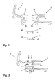
- FIG. 1 is made of a first frame part profile 1 and a second frame part profile 2 and from a first spacer bar profile 3 and a second spacer bar profile 4 a Frame for a window of a motorhome to manufacture.
- Both Frame sections 1, 2 are extruded rectilinear Profile bars made of aluminum.
- the spacer bar profiles 3, 4 are made of polyamide by an extrusion process Service.
- the first frame part profile 1 has Distanzstegitorn 5, 6, extending from perpendicular to the plane of Fig. 1 Recording side walls 7, 8, 9 are limited.
- Corresponding has the second frame part profile 2 Distanzstegitn 10, 11th with receiving side walls 12, 13, 14 on.
- the first spacer bar profile 3 is with edge thickening 15, 16, the second spacer bar profile 4 with edge thickening 17, 18 provided.
- the frame part profiles 1, 2 and the spacer bar profiles are located 3, 4 each as profile bars with, for example 6 m in length.
- the frame part profiles 1, 2 and the spacer bar profiles 3, 4 are to the unit shown in Fig. 2 preliminary with each other connected.
- the first spacer bar profile 3 in profile longitudinal direction in the Distanzstegage 5 at the first frame part profile 1 and in the spacer bar recording 10 introduced to the second frame part profile 2.
- the second Distanzstegprofil 4 in the Distanzstegor 6 on the first frame part profile 1 and in the Distanzstegage 11 on the second frame part profile. 2 inserted. This then results in the conditions shown in Fig. 2.
- the first spacer bar profile 3 lies with its edge thickening 15, 16 in the Distanzstegagen 5, 10 to the Frame part profiles 1, 2.
- the edge thickening 17, 18 at the second Distanzstegprofil 4 are located inside the Distanzstegitn 6, 11.
- the frame part profiles 1, 2 on the one hand and the Distanzstegprofile 3, 4 on the other hand are doing with relatively large game in profile transverse direction to each other held.
- the frame part profiles can be 1, 2 and the Distanzstegprofile 3, 4 thus relative to each other align.
- a minor Friction between the frame part profiles 1, 2 and the Distanzstegprofilen 3, 4 overcome.
- Such a thing Aligning is especially possible automatically when the Frame part profiles 1, 2 and the Distanzstegprofile 3, 4 in one further manufacturing step collectively to the desired Frame to be bent. May be before Bending of the from the frame sections 1, 2 and the Distanzstegprofilen 3, 4 existing linear unit a section corresponding to the circumference of the frame to be manufactured cut to length. Due to the relative longitudinal mobility the frame part profiles 1, 2 and the Distanzstegprofile 3, 4th results in a distortion-free, inherently stable frame. In installation position this frame summarizes a section in a in Fig. 3rd Dashboard shown side wall 19 of a motorhome. In Fig. 3 indicated by dash-dotted lines is a frame main plane 20 of the finished frame.
- the finished frame is under heat powder coated.
Landscapes
- Engineering & Computer Science (AREA)
- Civil Engineering (AREA)
- Structural Engineering (AREA)
- Wing Frames And Configurations (AREA)
- Body Structure For Vehicles (AREA)
- Automobile Manufacture Line, Endless Track Vehicle, Trailer (AREA)
- Power-Operated Mechanisms For Wings (AREA)
Abstract
Description
- Fig. 1
- zwei Rahmenteilprofile sowie zwei Distanzstegprofile jeweils im Querschnitt,
- Fig. 2
- die vorläufig miteinander verbundenen Rahmenteil- und Distanzstegprofile nach Fig. 1 und
- Fig. 3
- die endgültig miteinander verbundenen Rahmenteil- und Distanzstegprofile nach den Fign. 1 und 2.
Claims (6)
- Verfahren zum Herstellen eines Rahmens für ein Fenster, eine Tür, eine Klappe oder dergleichen, insbesondere an einem Wohnwagen oder einem Reisemobil, mit zwei in Rahmenumfangsrichtung verlaufenden und parallel zu der Rahmenhauptebene (20) voneinander getrennten Rahmenteilen sowie mit wenigstens einem sich zwischen den Rahmenteilen in Rahmenumfangsrichtung erstreckenden Distanzsteg aus wärmedämmendem Material, wobei wenigstens ein geradliniges Distanzstegprofil (3, 4) aus plastisch verformbarem Material in Distanzstegaufnahmen (5, 10; 6, 11) an zwei geradlinigen Rahmenteilprofilen (1, 2) aus plastisch verformbarem Material eingeführt und an den Distanzstegaufnahmen (5, 10; 6, 11) mit den Rahmenteilprofilen (1, 2) in Profilquerrichtung wirksam verbunden wird und wobei anschließend die Rahmenteilprofile (1, 2) sowie das Distanzstegprofil (3, 4) gemeinschaftlich in eine Rahmenform gebogen werden, dadurch gekennzeichnet, dass das Distanzstegprofil (3, 4) und die Rahmenteilprofile (1, 2) an den Distanzstegaufnahmen (5, 10; 6, 11) mit relativer Längsbeweglichkeit des Distanzstegprofils (3, 4) einerseits und wenigstens eines der Rahmenteilprofile (1, 2) andererseits und in Profilquerrichtung wirksam miteinander verbunden werden.
- Verfahren nach Anspruch 1, dadurch gekennzeichnet, dass wenigstens ein Distanzstegprofil (3, 4) und die Rahmenteilprofile (1, 2) mit relativer Längsbeweglichkeit des Distanzstegprofils (3, 4) einerseits und beider Rahmenteilprofile (1, 2) andererseits und in Profilquerrichtung wirksam miteinander verbunden werden.
- Verfahren nach einem der vorhergehenden Ansprüche, dadurch gekennzeichnet, dass wenigstens ein Distanzstegprofil (3, 4) an zumindest einem Rahmenteilprofil (1, 2) in eine Distanzstegaufnahme (5, 10; 6, 11) mit in Profillängsrichtung verlaufenden Aufnahmeseitenwänden (7, 8, 9; 12, 13, 14) eingeführt und das Distanzstegprofil (3, 4) sowie das Rahmenteilprofil (1, 2) unter Verformen wenigstens einer der Aufnahmeseitenwände (7, 8, 9; 12, 13, 14) mit relativer Längsbeweglichkeit und in Profilquerrichtung wirksam miteinander verbunden werden.
- Verfahren nach einem der vorhergehenden Ansprüche, dadurch gekennzeichnet, dass wenigstens eine der Aufnahmeseitenwände (7, 8, 9; 12, 13, 14) durch rollende Kraftbeaufschlagung verformt und dadurch wenigstens ein Distanzstegprofil (3, 4) sowie zumindest ein Rahmenteilprofil (1, 2) mit relativer Längsbeweglichkeit und in Profilquerrichtung wirksam miteinander verbunden werden.
- Verfahren nach einem der vorhergehenden Ansprüche, dadurch gekennzeichnet, dass wenigstens ein Distanzstegprofil (3, 4) aus hitzebeständigem Material verwendet wird und dass wenigstens ein Rahmenteil nach dem gemeinschaftlichen Biegen des betreffenden Rahmenteilprofils (1, 2) und des betreffenden Distanzstegprofils (3, 4) unter Hitzeeinwirkung behandelt, insbesondere beschichtet wird.
- Verfahren nach einem der vorhergehenden Ansprüche, dadurch gekennzeichnet, dass wenigstens ein Rahmenteilprofil (1, 2) aus Aluminium und/oder wenigstens ein Distanzstegprofil (3, 4) aus wärmedämmendem Kunststoff, insbesondere aus Polyamid, verwendet wird.
Applications Claiming Priority (2)
| Application Number | Priority Date | Filing Date | Title |
|---|---|---|---|
| DE10335276A DE10335276A1 (de) | 2003-08-01 | 2003-08-01 | Verfahren zum Herstellen eines Rahmens insbesondere für ein Fenster oder eine Tür an einem Wohnwagen oder einem Reisemobil |
| DE10335276 | 2003-08-01 |
Publications (3)
| Publication Number | Publication Date |
|---|---|
| EP1503023A2 true EP1503023A2 (de) | 2005-02-02 |
| EP1503023A3 EP1503023A3 (de) | 2006-01-18 |
| EP1503023B1 EP1503023B1 (de) | 2010-03-03 |
Family
ID=33521526
Family Applications (1)
| Application Number | Title | Priority Date | Filing Date |
|---|---|---|---|
| EP04017176A Expired - Lifetime EP1503023B1 (de) | 2003-08-01 | 2004-07-21 | Verfahren zum Herstellen eines Rahmens insbesondere für ein Fenster oder eine Tür an einem Wohnwagen oder einem Reisemobil |
Country Status (5)
| Country | Link |
|---|---|
| EP (1) | EP1503023B1 (de) |
| AT (1) | ATE459777T1 (de) |
| DE (2) | DE10335276A1 (de) |
| DK (1) | DK1503023T3 (de) |
| ES (1) | ES2342165T3 (de) |
Cited By (3)
| Publication number | Priority date | Publication date | Assignee | Title |
|---|---|---|---|---|
| USD1038852S1 (en) | 2019-08-21 | 2024-08-13 | Dometic Sweden Ab | Window |
| US12269321B2 (en) | 2019-08-21 | 2025-04-08 | Dometic Sweden Ab | Device for supporting a frame in an opening, a frame with such a device, a window, a recreational vehicle with such a frame or window and method for supporting the frame or the window in the opening |
| US12434543B2 (en) | 2019-08-21 | 2025-10-07 | Dometic Sweden Ab | Window, recreational vehicle with the window and methods for manufacturing and operating the window |
Family Cites Families (9)
| Publication number | Priority date | Publication date | Assignee | Title |
|---|---|---|---|---|
| CA1098767A (en) * | 1979-10-05 | 1981-04-07 | Jack Zintel | Multiple glazing assembly |
| DE8223301U1 (de) * | 1982-08-18 | 1982-12-30 | Michel, Hans, 7108 Möckmühl | Mehrteiliger profilrahmen, insbesondere fuer fenster und tueren |
| DE3315069C2 (de) * | 1983-04-26 | 1987-04-09 | eurAl Firmengruppe für Fenster- und Türensysteme GmbH, 3167 Burgdorf | Verbundprofil, insbesondere für Fenster und Türen, Verfahren zur Herstellung des Verbundprofiles sowie Werkzeug zur Durchführung des Verfahrens |
| DE3334332A1 (de) * | 1983-09-22 | 1985-04-04 | Julius & August Erbslöh GmbH & Co, 5600 Wuppertal | Verfahren und hohlkoerper zur herstellung einer gleitfuehrung zwischen zwei relativ zueinander beweglichen bauteilen |
| DE3501233A1 (de) * | 1985-01-16 | 1986-07-17 | IsKoAl Firmengruppe für Fenster- und Türsysteme GmbH, 3167 Burgdorf | Verfahren zur herstellung eines mehrteiligen profilrahmens |
| DE4203483A1 (de) * | 1992-02-07 | 1993-08-12 | Bernhard Kreye | Profil aus metall fuer den kreis- oder ovalfoermigen rahmen, insbesondere fluegelrahmen eines rundfensters |
| DE19637858A1 (de) * | 1996-09-17 | 1998-04-02 | Schueco Int Kg | Wärmegedämmtes Verbundprofil für Türen, Fenster oder Fassaden |
| NL1013879C2 (nl) * | 1999-12-17 | 2000-10-03 | Gemert Repair B V Van | Werkwijze voor het vervaardigen van een omlijsting voor een raam met afgeronde hoeken, alsmede omlijsting vervaardigd volgens de werkwijze. |
| NL1014407C2 (nl) * | 2000-02-17 | 2001-09-07 | David Wilhelm Zoetmulder | Raamconstructie en raamprofiel met onderbroken koudebrug. |
-
2003
- 2003-08-01 DE DE10335276A patent/DE10335276A1/de not_active Withdrawn
-
2004
- 2004-07-21 DK DK04017176.1T patent/DK1503023T3/da active
- 2004-07-21 DE DE502004010836T patent/DE502004010836D1/de not_active Expired - Lifetime
- 2004-07-21 AT AT04017176T patent/ATE459777T1/de not_active IP Right Cessation
- 2004-07-21 ES ES04017176T patent/ES2342165T3/es not_active Expired - Lifetime
- 2004-07-21 EP EP04017176A patent/EP1503023B1/de not_active Expired - Lifetime
Cited By (3)
| Publication number | Priority date | Publication date | Assignee | Title |
|---|---|---|---|---|
| USD1038852S1 (en) | 2019-08-21 | 2024-08-13 | Dometic Sweden Ab | Window |
| US12269321B2 (en) | 2019-08-21 | 2025-04-08 | Dometic Sweden Ab | Device for supporting a frame in an opening, a frame with such a device, a window, a recreational vehicle with such a frame or window and method for supporting the frame or the window in the opening |
| US12434543B2 (en) | 2019-08-21 | 2025-10-07 | Dometic Sweden Ab | Window, recreational vehicle with the window and methods for manufacturing and operating the window |
Also Published As
| Publication number | Publication date |
|---|---|
| DE10335276A1 (de) | 2005-03-03 |
| DK1503023T3 (da) | 2010-05-10 |
| EP1503023A3 (de) | 2006-01-18 |
| DE502004010836D1 (de) | 2010-04-15 |
| ATE459777T1 (de) | 2010-03-15 |
| EP1503023B1 (de) | 2010-03-03 |
| ES2342165T3 (es) | 2010-07-02 |
Similar Documents
| Publication | Publication Date | Title |
|---|---|---|
| DE69407977T2 (de) | Raumfachwerk-vorrichtung und verfahren zu deren herstellung | |
| EP2942466B1 (de) | Verbundprofil mit Lastabtragungseinrichtungen für Befestigungsmittel eines Funktionselementes, insbesondere ein Bandelement und Verfahren zur Montage eines solchen Funktionselementes | |
| EP2476853B1 (de) | Verbundprofil für Fenster, Türen und Fassaden sowie Verfahren zu dessen Herstellung | |
| DE3006056A1 (de) | Torblatt fuer ein deckenglieder- oder rolltor | |
| DE102004043658B4 (de) | Hohlkörperbauteil und Verfahren zur Herstellung eines derartigen Bauteiles | |
| EP0425836A2 (de) | Verfahren zur Herstellung einer Teleskopabdeckung | |
| DE102018131967A1 (de) | Verfahren zum Kalibrieren eines gekrümmten metallischen Hohlkammerprofils | |
| EP1503023A2 (de) | Verfahren zum Herstellen eines Rahmens insbesondere für ein Fenster oder eine Tür an einem Wohnwagen oder einem Reisemobil | |
| EP1873869B1 (de) | Elektrisches Modul | |
| EP2977119B1 (de) | Verfahren zum herstellen eines torsionsprofils aus einer platine sowie torsionsprofil | |
| DE102015116588A1 (de) | Bausatz für einen Spannrahmen | |
| DE102008020988A1 (de) | Wärmeisolierendes Rahmenprofil für die Herstellung von Tür- und Fensterrahmen | |
| DE102014206196A1 (de) | Dachrahmen für eine Fahrzeugkarosserie | |
| DE2810630A1 (de) | Herstellungsverfahren eines verbundprofils und verbundprofil | |
| WO1999067495A1 (de) | Verbindung für kunststoffhohlprofile | |
| DE10221880A1 (de) | Verfahren zur Herstellung eines verstärkten Rohres oder Bleches | |
| EP1215360B9 (de) | Verbundprofil | |
| EP3396096A1 (de) | Verbundprofil sowie verfahren zur herstellung des verbundprofils | |
| EP0007496A1 (de) | Verfahren zur Herstellung eines wärmegedämmten Metallprofils | |
| DE102006040519B4 (de) | Verfahren zur Herstellung einer Stromschiene | |
| EP3048232B1 (de) | Metallprofil, Verbundprofil mit einem solchen Metallprofil sowie Verfahren zur Herstellung des Metallprofils | |
| EP2316712B1 (de) | Verbundprofil bestehend aus wenigstens einem ersten und zweiten Metallprofilteil | |
| DE102012014790A1 (de) | Montageschiene sowie Verfahren zu deren Herstellung | |
| DE69809823T3 (de) | Verfahren zum Verbinden eines Schlauches mit einem Rohr, Kupplung und Befestigungsring zum Durchführen dieses Verfahrens | |
| DE102021126059B4 (de) | Tragprofil für eine Fassade |
Legal Events
| Date | Code | Title | Description |
|---|---|---|---|
| PUAI | Public reference made under article 153(3) epc to a published international application that has entered the european phase |
Free format text: ORIGINAL CODE: 0009012 |
|
| AK | Designated contracting states |
Kind code of ref document: A2 Designated state(s): AT BE BG CH CY CZ DE DK EE ES FI FR GB GR HU IE IT LI LU MC NL PL PT RO SE SI SK TR |
|
| AX | Request for extension of the european patent |
Extension state: AL HR LT LV MK |
|
| PUAL | Search report despatched |
Free format text: ORIGINAL CODE: 0009013 |
|
| AK | Designated contracting states |
Kind code of ref document: A3 Designated state(s): AT BE BG CH CY CZ DE DK EE ES FI FR GB GR HU IE IT LI LU MC NL PL PT RO SE SI SK TR |
|
| AX | Request for extension of the european patent |
Extension state: AL HR LT LV MK |
|
| RAP1 | Party data changed (applicant data changed or rights of an application transferred) |
Owner name: DOMETIC SEITZ GMBH |
|
| 17P | Request for examination filed |
Effective date: 20060308 |
|
| AKX | Designation fees paid |
Designated state(s): AT BE BG CH CY CZ DE DK EE ES FI FR GB GR HU IE IT LI LU MC NL PL PT RO SE SI SK TR |
|
| 17Q | First examination report despatched |
Effective date: 20080110 |
|
| GRAP | Despatch of communication of intention to grant a patent |
Free format text: ORIGINAL CODE: EPIDOSNIGR1 |
|
| GRAS | Grant fee paid |
Free format text: ORIGINAL CODE: EPIDOSNIGR3 |
|
| GRAA | (expected) grant |
Free format text: ORIGINAL CODE: 0009210 |
|
| AK | Designated contracting states |
Kind code of ref document: B1 Designated state(s): AT BE BG CH CY CZ DE DK EE ES FI FR GB GR HU IE IT LI LU MC NL PL PT RO SE SI SK TR |
|
| REG | Reference to a national code |
Ref country code: GB Ref legal event code: FG4D Free format text: NOT ENGLISH |
|
| REG | Reference to a national code |
Ref country code: CH Ref legal event code: EP |
|
| REG | Reference to a national code |
Ref country code: IE Ref legal event code: FG4D |
|
| REF | Corresponds to: |
Ref document number: 502004010836 Country of ref document: DE Date of ref document: 20100415 Kind code of ref document: P |
|
| REG | Reference to a national code |
Ref country code: DK Ref legal event code: T3 |
|
| REG | Reference to a national code |
Ref country code: SE Ref legal event code: TRGR |
|
| REG | Reference to a national code |
Ref country code: NL Ref legal event code: T3 |
|
| REG | Reference to a national code |
Ref country code: ES Ref legal event code: FG2A Ref document number: 2342165 Country of ref document: ES Kind code of ref document: T3 |
|
| PG25 | Lapsed in a contracting state [announced via postgrant information from national office to epo] |
Ref country code: PL Free format text: LAPSE BECAUSE OF FAILURE TO SUBMIT A TRANSLATION OF THE DESCRIPTION OR TO PAY THE FEE WITHIN THE PRESCRIBED TIME-LIMIT Effective date: 20100303 Ref country code: SI Free format text: LAPSE BECAUSE OF FAILURE TO SUBMIT A TRANSLATION OF THE DESCRIPTION OR TO PAY THE FEE WITHIN THE PRESCRIBED TIME-LIMIT Effective date: 20100303 |
|
| REG | Reference to a national code |
Ref country code: IE Ref legal event code: FD4D |
|
| PG25 | Lapsed in a contracting state [announced via postgrant information from national office to epo] |
Ref country code: GR Free format text: LAPSE BECAUSE OF FAILURE TO SUBMIT A TRANSLATION OF THE DESCRIPTION OR TO PAY THE FEE WITHIN THE PRESCRIBED TIME-LIMIT Effective date: 20100604 Ref country code: RO Free format text: LAPSE BECAUSE OF FAILURE TO SUBMIT A TRANSLATION OF THE DESCRIPTION OR TO PAY THE FEE WITHIN THE PRESCRIBED TIME-LIMIT Effective date: 20100303 Ref country code: CY Free format text: LAPSE BECAUSE OF FAILURE TO SUBMIT A TRANSLATION OF THE DESCRIPTION OR TO PAY THE FEE WITHIN THE PRESCRIBED TIME-LIMIT Effective date: 20100303 Ref country code: EE Free format text: LAPSE BECAUSE OF FAILURE TO SUBMIT A TRANSLATION OF THE DESCRIPTION OR TO PAY THE FEE WITHIN THE PRESCRIBED TIME-LIMIT Effective date: 20100303 Ref country code: IE Free format text: LAPSE BECAUSE OF FAILURE TO SUBMIT A TRANSLATION OF THE DESCRIPTION OR TO PAY THE FEE WITHIN THE PRESCRIBED TIME-LIMIT Effective date: 20100303 |
|
| PGFP | Annual fee paid to national office [announced via postgrant information from national office to epo] |
Ref country code: ES Payment date: 20100830 Year of fee payment: 7 Ref country code: NL Payment date: 20100726 Year of fee payment: 7 |
|
| PG25 | Lapsed in a contracting state [announced via postgrant information from national office to epo] |
Ref country code: SK Free format text: LAPSE BECAUSE OF FAILURE TO SUBMIT A TRANSLATION OF THE DESCRIPTION OR TO PAY THE FEE WITHIN THE PRESCRIBED TIME-LIMIT Effective date: 20100303 Ref country code: CZ Free format text: LAPSE BECAUSE OF FAILURE TO SUBMIT A TRANSLATION OF THE DESCRIPTION OR TO PAY THE FEE WITHIN THE PRESCRIBED TIME-LIMIT Effective date: 20100303 Ref country code: BG Free format text: LAPSE BECAUSE OF FAILURE TO SUBMIT A TRANSLATION OF THE DESCRIPTION OR TO PAY THE FEE WITHIN THE PRESCRIBED TIME-LIMIT Effective date: 20100603 |
|
| PGFP | Annual fee paid to national office [announced via postgrant information from national office to epo] |
Ref country code: AT Payment date: 20100721 Year of fee payment: 7 Ref country code: DE Payment date: 20100723 Year of fee payment: 7 Ref country code: FI Payment date: 20100721 Year of fee payment: 7 Ref country code: FR Payment date: 20100802 Year of fee payment: 7 Ref country code: IT Payment date: 20100728 Year of fee payment: 7 Ref country code: LU Payment date: 20100723 Year of fee payment: 7 Ref country code: SE Payment date: 20100723 Year of fee payment: 7 |
|
| PGFP | Annual fee paid to national office [announced via postgrant information from national office to epo] |
Ref country code: GB Payment date: 20100726 Year of fee payment: 7 |
|
| PLBE | No opposition filed within time limit |
Free format text: ORIGINAL CODE: 0009261 |
|
| STAA | Information on the status of an ep patent application or granted ep patent |
Free format text: STATUS: NO OPPOSITION FILED WITHIN TIME LIMIT |
|
| PG25 | Lapsed in a contracting state [announced via postgrant information from national office to epo] |
Ref country code: PT Free format text: LAPSE BECAUSE OF FAILURE TO SUBMIT A TRANSLATION OF THE DESCRIPTION OR TO PAY THE FEE WITHIN THE PRESCRIBED TIME-LIMIT Effective date: 20100705 |
|
| PGFP | Annual fee paid to national office [announced via postgrant information from national office to epo] |
Ref country code: DK Payment date: 20100726 Year of fee payment: 7 |
|
| 26N | No opposition filed |
Effective date: 20101206 |
|
| PG25 | Lapsed in a contracting state [announced via postgrant information from national office to epo] |
Ref country code: MC Free format text: LAPSE BECAUSE OF NON-PAYMENT OF DUE FEES Effective date: 20100731 |
|
| PGFP | Annual fee paid to national office [announced via postgrant information from national office to epo] |
Ref country code: BE Payment date: 20100727 Year of fee payment: 7 |
|
| REG | Reference to a national code |
Ref country code: CH Ref legal event code: PL |
|
| PG25 | Lapsed in a contracting state [announced via postgrant information from national office to epo] |
Ref country code: CH Free format text: LAPSE BECAUSE OF NON-PAYMENT OF DUE FEES Effective date: 20100731 Ref country code: LI Free format text: LAPSE BECAUSE OF NON-PAYMENT OF DUE FEES Effective date: 20100731 |
|
| BERE | Be: lapsed |
Owner name: DOMETIC SEITZ G.M.B.H. Effective date: 20110731 |
|
| REG | Reference to a national code |
Ref country code: NL Ref legal event code: V1 Effective date: 20120201 |
|
| REG | Reference to a national code |
Ref country code: SE Ref legal event code: EUG |
|
| REG | Reference to a national code |
Ref country code: DK Ref legal event code: EBP |
|
| GBPC | Gb: european patent ceased through non-payment of renewal fee |
Effective date: 20110721 |
|
| REG | Reference to a national code |
Ref country code: AT Ref legal event code: MM01 Ref document number: 459777 Country of ref document: AT Kind code of ref document: T Effective date: 20110721 |
|
| REG | Reference to a national code |
Ref country code: FR Ref legal event code: ST Effective date: 20120330 |
|
| PG25 | Lapsed in a contracting state [announced via postgrant information from national office to epo] |
Ref country code: FR Free format text: LAPSE BECAUSE OF NON-PAYMENT OF DUE FEES Effective date: 20110801 Ref country code: BE Free format text: LAPSE BECAUSE OF NON-PAYMENT OF DUE FEES Effective date: 20110731 Ref country code: DE Free format text: LAPSE BECAUSE OF NON-PAYMENT OF DUE FEES Effective date: 20120201 |
|
| REG | Reference to a national code |
Ref country code: DE Ref legal event code: R119 Ref document number: 502004010836 Country of ref document: DE Effective date: 20120201 |
|
| PG25 | Lapsed in a contracting state [announced via postgrant information from national office to epo] |
Ref country code: NL Free format text: LAPSE BECAUSE OF NON-PAYMENT OF DUE FEES Effective date: 20120201 Ref country code: IT Free format text: LAPSE BECAUSE OF NON-PAYMENT OF DUE FEES Effective date: 20110721 Ref country code: FI Free format text: LAPSE BECAUSE OF NON-PAYMENT OF DUE FEES Effective date: 20110721 |
|
| PG25 | Lapsed in a contracting state [announced via postgrant information from national office to epo] |
Ref country code: GB Free format text: LAPSE BECAUSE OF NON-PAYMENT OF DUE FEES Effective date: 20110721 |
|
| PG25 | Lapsed in a contracting state [announced via postgrant information from national office to epo] |
Ref country code: DK Free format text: LAPSE BECAUSE OF NON-PAYMENT OF DUE FEES Effective date: 20110731 |
|
| PG25 | Lapsed in a contracting state [announced via postgrant information from national office to epo] |
Ref country code: HU Free format text: LAPSE BECAUSE OF FAILURE TO SUBMIT A TRANSLATION OF THE DESCRIPTION OR TO PAY THE FEE WITHIN THE PRESCRIBED TIME-LIMIT Effective date: 20100904 |
|
| PG25 | Lapsed in a contracting state [announced via postgrant information from national office to epo] |
Ref country code: TR Free format text: LAPSE BECAUSE OF FAILURE TO SUBMIT A TRANSLATION OF THE DESCRIPTION OR TO PAY THE FEE WITHIN THE PRESCRIBED TIME-LIMIT Effective date: 20100303 |
|
| REG | Reference to a national code |
Ref country code: ES Ref legal event code: FD2A Effective date: 20121122 |
|
| PG25 | Lapsed in a contracting state [announced via postgrant information from national office to epo] |
Ref country code: AT Free format text: LAPSE BECAUSE OF NON-PAYMENT OF DUE FEES Effective date: 20110721 |
|
| PG25 | Lapsed in a contracting state [announced via postgrant information from national office to epo] |
Ref country code: ES Free format text: LAPSE BECAUSE OF NON-PAYMENT OF DUE FEES Effective date: 20110722 |
|
| PG25 | Lapsed in a contracting state [announced via postgrant information from national office to epo] |
Ref country code: SE Free format text: LAPSE BECAUSE OF NON-PAYMENT OF DUE FEES Effective date: 20110722 |
|
| PG25 | Lapsed in a contracting state [announced via postgrant information from national office to epo] |
Ref country code: LU Free format text: LAPSE BECAUSE OF NON-PAYMENT OF DUE FEES Effective date: 20110721 |