EP1502989A1 - Stoffauflauf - Google Patents
Stoffauflauf Download PDFInfo
- Publication number
- EP1502989A1 EP1502989A1 EP04102968A EP04102968A EP1502989A1 EP 1502989 A1 EP1502989 A1 EP 1502989A1 EP 04102968 A EP04102968 A EP 04102968A EP 04102968 A EP04102968 A EP 04102968A EP 1502989 A1 EP1502989 A1 EP 1502989A1
- Authority
- EP
- European Patent Office
- Prior art keywords
- sensor
- sieve
- light beam
- pulp suspension
- jet
- Prior art date
- Legal status (The legal status is an assumption and is not a legal conclusion. Google has not performed a legal analysis and makes no representation as to the accuracy of the status listed.)
- Granted
Links
Images
Classifications
-
- D—TEXTILES; PAPER
- D21—PAPER-MAKING; PRODUCTION OF CELLULOSE
- D21F—PAPER-MAKING MACHINES; METHODS OF PRODUCING PAPER THEREON
- D21F1/00—Wet end of machines for making continuous webs of paper
- D21F1/02—Head boxes of Fourdrinier machines
- D21F1/028—Details of the nozzle section
-
- D—TEXTILES; PAPER
- D21—PAPER-MAKING; PRODUCTION OF CELLULOSE
- D21F—PAPER-MAKING MACHINES; METHODS OF PRODUCING PAPER THEREON
- D21F1/00—Wet end of machines for making continuous webs of paper
- D21F1/02—Head boxes of Fourdrinier machines
-
- D—TEXTILES; PAPER
- D21—PAPER-MAKING; PRODUCTION OF CELLULOSE
- D21G—CALENDERS; ACCESSORIES FOR PAPER-MAKING MACHINES
- D21G9/00—Other accessories for paper-making machines
- D21G9/0009—Paper-making control systems
Definitions
- the invention relates to a device for applying a pulp suspension by means of a nozzle arrangement on an endlessly rotating sieve or between two endlessly rotating screens of a machine for producing a fibrous web from a pulp suspension, in particular headbox for a paper or Cardboard machine, with a means for applying the pulp suspension in Shape of a jet on the sieve or one of the sieves.
- From DE 40 19 593 C2 is a headbox with a nozzle arrangement for a Paper machine known.
- the headbox is with a transverse and upside down distributors extending across the working width of the paper machine for distribution the supplied pulp suspension.
- a turbulence generator in the Headbox has a variety of holes or channels. It is a nozzle for the outflow of the pulp suspension forming machine wide outlet channel with an outlet gap for dispensing the stock suspension to a Paper machine screen available.
- the sectioned section is followed by a turbulence generator Homogenization of the pulp suspension on.
- the headbox "shows" here basically in wire direction.
- So far headboxes are designed for a desired Strahlauf&ddling that visually inspected and optimized during operation of the machine. He will be the Operating conditions such as the beam thickness and the jet velocity, adjusted. The environment and the beam impact point for visual optimization are particular not always suitable for gap shapers. Also disturb Edge effects in the beam the insight over the entire width of the beam.
- This object is achieved in a headbox of the aforementioned Art solved by at least one optical measuring device for adjusting of the beam impact point on the screen or at least one of the screens available is.
- the invention thus provides an optical auxiliary device for adjusting the Beam impact point created.
- the invention is not limited to use only Spaltformern limited, but is suitable, for example, for Hlybridformer.
- the measuring device comprises at least one Means for generating a coherent light beam, in particular a laser, and at least one sensor for receiving the light beam.
- the sensors or Receivers are arranged on a bar, for example.
- the at least one sensor as a sensor for the beam the pulp suspension transmitted light on the means for generating of the coherent light beam opposite side of the beam Fibrous suspension is arranged so that the light is at an acute angle is transmitted through the jet of pulp suspension.
- the senor is below the screen or one of the screens or arranged in extension of a screening table, around which a sieve is guided becomes.
- the sensor or the sensor arrangement outside the machine be reproducibly mounted.
- the setting for each application becomes preferably done at a standstill.
- the sensor is on a drainage element attached.
- the senor instead of the transmission principle is alternatively advantageous to the sensor as a sensor for light reflected from the jet of pulp suspension on the same Side of the jet of pulp suspension as the means for generating the coherent Light beam arranged.
- the senor is arranged on the same holding device as the means for generating the light beam.
- the sensor is advantageous on a sieve table or a drainage element one of the two screens or on a holder connected to the nozzle assembly arranged.
- the at least one means for Generating the light beam in the vicinity of the beam impact point of the fiber jet suspension arranged on the sieve or one of the sieves are provided.
- the at least one means for generating the Light beam and the at least one sensor optical means for influencing arrange the light beam such as lenses, apertures, semitransparent mirrors, interferometers or prisms or other focusing agents.
- the laser can be used, for example, the radiation surface or another hydraulic line, in particular the center of a separating wedge or an extension the level of a lip of the headbox, represent.
- the device comprises a display device to represent the points of impingement of the beam in a plane of the beam Jet of pulp suspension or on the surface of a sieve.
- a Arithmetic unit for determining the angle of incidence, the point of impact or the Impact surface of the light beam in a plane of the pulp suspension or on the Surface of a sieve.
- the invention also relates to a method for operating a device in one the principalsfomen shown above, wherein the device during the Standstill of the device or by means of a test liquid, in particular under Setting various parameters, is adjusted.
- advantages of the invention are that the beam contour of one of a coherent light emitting light source emitted light beam optically is displayed and the impact situation is sensed.
- the assembly The laser can be reproducibly made on the headbox.
- the angle at which the light is directed onto the jet of pulp suspension is emitted or by an optic when using a Laser or other coherent light source can be due to the beam fanning the turbulence can be represented.
- the beam top and the beam bottom are optionally represented by one laser each.
- the impact situation is, for example, by a sensor surface or bar with Receivers displayed in a display unit for displaying the beam impact position.
- the angle of incidence is approximately by a deformation of a Point of light or a surface of light from "round” to "elliptical” determined; additionally Correction factors are introduced, for example because of the sieve thickness.
- An advantage of the invention is also that a uniform quality of the Product is ensured during manufacture. The optimization times are reduced. Better commissioning results are achieved, and the Working conditions for the operating staff are improved.
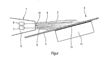
- This shows a schematic cross-sectional view of a Headbox of a gap former.
- the device comprises a headbox 1, from which in per se known Make a pulp suspension in a beam 2 on a gap 3 with two screens is applied, of which only one screen 4 is shown in the illustration becomes.
- a side surface 5 of the headbox nozzle 1 are two light sources 6, 7, in particular Laser light sources, arranged to generate coherent light beams. These each generate a light beam 8, 9, through the beam 2 of the pulp suspension shines through.
- Each of the light beams 8, 9 is thereby partially transmitted under refraction, partly absorbed and partly reflected.
- the device therefore becomes sensors for measuring the reflected or transmitted light beam used.
- a sensor 10 is below the screen 4 for detecting the beam through the second Transmitted light arranged, which also still passed from the screen 4 becomes.
- the sensor 10 is, for example, on a dewatering element 11 applied and comprises a receiver module with a sensor surface.
- a sensor which receives light that is reflected, for example, from the surface of the beam 2.
- a separating wedge 12 is arranged, so that the Beam 2 is emitted in two partial beams. Both partial beams can be optically individually examine and analyze.
- the setting of the directions under which the light rays are emitted takes place either at a standstill or with one in comparison to the pulp suspension more transparent liquid, such as water, at different Working parameters, such. B. different speeds of the partial beams or the beam 2, occurring changes in advance to easily capture can and set up the arrangement of the sensors accordingly. Likewise, such a calibration can also take account of correction factors. on different screen thicknesses or other parameters of the Twin-wire former based.
- the values obtained by the optical measurements can be used for example, in a turbulence generator integrated in the headbox nozzle Make adjustments or adjustments of the holes or channels or the Adjust the width or height of the nozzle from which the pulp suspension flows out.
Landscapes
- Paper (AREA)
- Crystals, And After-Treatments Of Crystals (AREA)
Abstract
Description
- 1
- Stoffauflaufdüse
- 2
- Strahl
- 3
- Spaltformer
- 4
- Sieb
- 5
- Seitenfläche
- 6
- Lichtquelle
- 7
- Lichtquelle
- 8
- Lichtstrahl
- 9
- Lichtstrahl
- 10
- Sensor
- 11
- Entwässerungselement
- 12
- Trennkeil
Claims (13)
- Vorrichtung zum Aufbringen einer Faserstoffsuspension mittels einer Düsenanordnung auf ein endlos umlaufendes Sieb (4) oder zwischen zwei endlos umlaufende Siebe einer Maschine zur Herstellung einer Faserstoffbahn aus einer Faserstoffsuspension, insbesondere Stoffauflauf füreine Papier- oder Kartonmaschine, mit einem Mittel (1) zum Aufbringen der Faserstoffsuspension in Form eines Strahls (2) auf das Sieb (4) oder eines der Siebe,
dadurch gekennzeichnet, dass mindestens eine optische Messeinrichtung zum Justieren des Strahlauftreffpunkts auf das Sieb (4) oder zumindest eines der Siebe vorhanden ist. - Vorrichtung nach Anspruch 1,
dadurch gekennzeichnet, dass die mindestens eine Messeinrichtung mindestens ein Mittel (6, 7) zum Erzeugen eines kohärenten Lichtstrahls (8, 9), insbesondere einen Laser, und mindestens einen Sensor (10) zum Empfangen des Lichtstrahls (8, 9) umfasst. - Vorrichtung nach Anspruch 2,
dadurch gekennzeichnet, dass der mindestens eine Sensor (10) als Sensor für von dem Strahl der Faserstoffsuspension transmittiertes Licht auf der dem Mittel (6, 7) zum Erzeugen des Lichtstrahls (8, 9) gegenüberliegenden Seite des Strahls (2) der Faserstoffsuspension angeordnet ist. - Vorrichtung nach Anspruch 3,
dadurch gekennzeichnet, dass der mindestens eine Sensor (10) unterhalb des Siebs (4) oder eines der Siebe oder in Verlängerung eines Siebtisches angeordnet ist, um den das Sieb (4) bzw. eines der Siebe herumgeführt ist bzw. sind, oder dass der Sensor (10) an einem Entwässerungselement befestigt ist. - Vorrichtung nach Anspruch 2,
dadurch gekennzeichnet, dass der mindestens eine Sensor (10) als Sensor für von dem Strahl der Faserstoffsuspension reflektiertes Licht auf derselben Seite des Strahls der Faserstoffsuspension wie das Mittel (6, 7) zum Erzeugen des Lichtstrahls (8, 9) angeordnet ist. - Vorrichtung nach Anspruch 5,
dadurch gekennzeichnet, dass der mindestens eine Sensor (10) an derselben Halteeinrichtung angeordnet ist wie das Mittel (6, 7) zum Erzeugen des Lichtstrahls (8, 9). - Vorrichtung nach Anspruch 5 oder 6,
dadurch gekennzeichnet, dass der mindestens eine Sensor (10) an einem Siebtisch oder einem Entwässerungselement eines der beiden Siebe oder an einer mit der Düsenanordnung verbundenen Halterung angeordnet ist. - Vorrichtung nach einem der Ansprüche 2 bis 7,
dadurch gekennzeichnet, dass das mindestens eine Mittel (6, 7) zum Erzeugen des Lichtstrahls (8, 9) in der Nähedes Strahlauftreffpunktes der Faserstrahlsuspension auf dem Sieb (4) bzw. einem der Siebe angeordnet ist. - Vorrichtung nach einem der Ansprüche 2 bis 8,
dadurch gekennzeichnet, dass zwischen dem mindestens einen Mittel (6, 7) zum Erzeugen des Lichtstrahls (8, 9) und dem mindestens einen Sensor (10) optische Mittel zur Beeinflussung des Lichtstrahls (8, 9) angeordnet sind. - Vorrichtung nach einem der Ansprüche 1 bis 9,
dadurch gekennzeichnet, dass durch das Mittel (6, 7) zur Erzeugung des Lichtstrahls die Strahloberflächeoder eine andere hydraulische Linie, insbesondere die Mitte eines Trennkeils (12) oder eine Verlängerung der Ebene einer Lippe des Mittels (1) zum Aufbringen der Faserstoffsuspension, darstellbar ist. - Vorrichtung nach einem der Ansprüche 1 bis 10,
dadurch gekennzeichnet, dass sie eine Anzeigeeinrichtung zur Darstellung der Auftreffpunkte des Lichtstrahls (8, 9) in einer Ebene des Strahls (2) der Faserstoffsuspension oder auf der Oberfläche eines Siebs (4) umfasst. - Vorrichtung nach einem der Ansprüche 1 bis 11,
dadurch gekennzeichnet, dass sie eine Recheneinheit zur Bestimmung des Auftreffwinkels, des Auftreffpunkts oder der Auftrefffläche des Lichtstrahls (8, 9) in einer Ebene der Faserstoffsuspension oder auf der Oberfläche eines Siebs umfasst. - Verfahren zum Betreiben einer Vorrichtung nach einem der Ansprüche1 bis 12,
dadurch gekennzeichnet, dass die Vorrichtung während des Stillstands der Vorrichtung oder mittels einer Testflüssigkeit, insbesondere unter Einstellung verschiedener Parameter, justiert wird.
Applications Claiming Priority (2)
| Application Number | Priority Date | Filing Date | Title |
|---|---|---|---|
| DE10333977 | 2003-07-25 | ||
| DE10333977A DE10333977A1 (de) | 2003-07-25 | 2003-07-25 | Stoffauflauf |
Publications (2)
| Publication Number | Publication Date |
|---|---|
| EP1502989A1 true EP1502989A1 (de) | 2005-02-02 |
| EP1502989B1 EP1502989B1 (de) | 2008-07-23 |
Family
ID=33521417
Family Applications (1)
| Application Number | Title | Priority Date | Filing Date |
|---|---|---|---|
| EP04102968A Expired - Lifetime EP1502989B1 (de) | 2003-07-25 | 2004-06-25 | Stoffauflaufvorrichtung und Verfahren zum Betreiben derselben |
Country Status (3)
| Country | Link |
|---|---|
| EP (1) | EP1502989B1 (de) |
| AT (1) | ATE402286T1 (de) |
| DE (2) | DE10333977A1 (de) |
Cited By (2)
| Publication number | Priority date | Publication date | Assignee | Title |
|---|---|---|---|---|
| WO2010015575A1 (de) * | 2008-08-08 | 2010-02-11 | Voith Patent Gmbh | Verfahren zum beeinflussen von mindestens einer betriebs- und/oder qualitätseigenschaft bei der herstellung einer faserstoffbahn und blattbildungssystem zur durchführung des verfahrens |
| CN101884972A (zh) * | 2009-05-11 | 2010-11-17 | 玛珂系统分析和开发有限公司 | 阀 |
Citations (3)
| Publication number | Priority date | Publication date | Assignee | Title |
|---|---|---|---|---|
| DE4239845A1 (en) * | 1992-11-05 | 1993-05-19 | Voith Gmbh J M | Paper-making inlet correction - uses correlated measurements from start and end of water extraction stage to calculate the settings |
| WO2001053603A1 (en) * | 2000-01-18 | 2001-07-26 | Stora Kopparbergs Bergslags Aktiebolag (Publ) | Method and device in connection with the production of paper or paperboard, and paper or paperboard product |
| WO2002046523A1 (en) * | 2000-12-07 | 2002-06-13 | Metso Paper, Inc. | Method and device for controlling the solids profile of a web in a wire section of a paper/board machine |
Family Cites Families (5)
| Publication number | Priority date | Publication date | Assignee | Title |
|---|---|---|---|---|
| DE4019593C2 (de) * | 1990-06-20 | 1994-01-20 | Voith Gmbh J M | Stoffauflauf für Papiermaschinen |
| DE19709294A1 (de) * | 1997-03-07 | 1998-09-10 | Voith Sulzer Papiermasch Gmbh | Siebpartie und Verfahren zur Blattbildung in einer Siebpartie |
| DE29713272U1 (de) * | 1997-07-25 | 1997-11-20 | Voith Sulzer Papiermaschinen GmbH, 89522 Heidenheim | Stoffauflauf zur Bildung einer Faserstoffsuspensionsschicht |
| DE19831612A1 (de) * | 1998-07-14 | 2000-01-20 | Voith Sulzer Papiermasch Gmbh | Meßsystem |
| FI20020890A7 (fi) * | 2002-05-10 | 2003-11-11 | Antti Niemi | Menetelmä ja laitteisto vesirajan määrittämiseksi ja vesirajaan perustuvaksi ohjaamiseksi Fourdrinier-paperikoneessa |
-
2003
- 2003-07-25 DE DE10333977A patent/DE10333977A1/de not_active Withdrawn
-
2004
- 2004-06-25 DE DE502004007649T patent/DE502004007649D1/de not_active Expired - Lifetime
- 2004-06-25 EP EP04102968A patent/EP1502989B1/de not_active Expired - Lifetime
- 2004-06-25 AT AT04102968T patent/ATE402286T1/de active
Patent Citations (3)
| Publication number | Priority date | Publication date | Assignee | Title |
|---|---|---|---|---|
| DE4239845A1 (en) * | 1992-11-05 | 1993-05-19 | Voith Gmbh J M | Paper-making inlet correction - uses correlated measurements from start and end of water extraction stage to calculate the settings |
| WO2001053603A1 (en) * | 2000-01-18 | 2001-07-26 | Stora Kopparbergs Bergslags Aktiebolag (Publ) | Method and device in connection with the production of paper or paperboard, and paper or paperboard product |
| WO2002046523A1 (en) * | 2000-12-07 | 2002-06-13 | Metso Paper, Inc. | Method and device for controlling the solids profile of a web in a wire section of a paper/board machine |
Cited By (2)
| Publication number | Priority date | Publication date | Assignee | Title |
|---|---|---|---|---|
| WO2010015575A1 (de) * | 2008-08-08 | 2010-02-11 | Voith Patent Gmbh | Verfahren zum beeinflussen von mindestens einer betriebs- und/oder qualitätseigenschaft bei der herstellung einer faserstoffbahn und blattbildungssystem zur durchführung des verfahrens |
| CN101884972A (zh) * | 2009-05-11 | 2010-11-17 | 玛珂系统分析和开发有限公司 | 阀 |
Also Published As
| Publication number | Publication date |
|---|---|
| EP1502989B1 (de) | 2008-07-23 |
| DE10333977A1 (de) | 2005-02-10 |
| DE502004007649D1 (de) | 2008-09-04 |
| ATE402286T1 (de) | 2008-08-15 |
Similar Documents
| Publication | Publication Date | Title |
|---|---|---|
| DE19510008C9 (de) | Verfahren und Vorrichtung zur Prozeßführung bei der Zellstoff- und/oder Papierherstellung | |
| DE69010976T2 (de) | Papierbahn formendes Verfahren und Vorrichtung. | |
| DE2857473C2 (de) | ||
| DE4005281C2 (de) | Stoffauflauf mit Regelung des Flächengewicht-Querprofiles über die Verdünnung der Fasersuspension | |
| WO1996029465A2 (de) | Verfahren und vorrichtung zur prozessführung bei der zellstoff- und/oder papierherstellung | |
| DE3806608A1 (de) | Verfahren zur geschwindigkeits- und/oder laengenmessung von endlosen textilen warenbahnen sowie vorrichtung zur durchfuehrung des verfahrens | |
| DE19850825C2 (de) | Verfahren und Vorrichtung zur Messung der Qualitätseigenschaften von Papier und/oder Pappe an laufenden Materialbahnen | |
| DE4239845A1 (en) | Paper-making inlet correction - uses correlated measurements from start and end of water extraction stage to calculate the settings | |
| EP1516954A2 (de) | Vorrichtung und Verfahren zur Beurteilung der Beschaffenheit mindestens eines umlaufenden Bandes | |
| EP1502989B1 (de) | Stoffauflaufvorrichtung und Verfahren zum Betreiben derselben | |
| AT505931B1 (de) | Blattbildungsverfahren und nasspartie zur herstellung einer faserstoffbahn | |
| DE3128156C2 (de) | Siebpartie einer Papiermaschine | |
| DE19503763A1 (de) | Vorrichtung zur Farbmessung | |
| DE3781372T2 (de) | Geraet zur prozessgekoppelten charakterisierung einer (papier-)bahnbildung. | |
| DE2754622A1 (de) | Former fuer eine papiermaschine | |
| DE60214139T2 (de) | Verfahren zum kontrollieren der sortiergüte über fliessmenge und konsistenz des halbstoffs | |
| WO2000036401A1 (de) | Verfahren und vorrichtung zur auswertung von spektroskopischen messungen an festen materialien mit räumlich und/oder zeitlich variierenden oberflächen | |
| EP0978587B1 (de) | Verfahren zur Einstellung eines gleichmässigen Eigenschaftsquerprofils einer Papierbahn | |
| EP1489224A1 (de) | Stoffauflauf | |
| DE4330546A1 (de) | Doppelsiebformer mit örtlich verstellbarer Entwässerungsleiste | |
| DE4219292A1 (de) | Doppelsiebformer | |
| DE4234940A1 (de) | Stoffauflauf mit flaechengewichts-querprofilregelung durch lokale konzentrationsaenderung | |
| EP1524363B1 (de) | Verfahren und Anordnung zur Bestimmung der Wasserdurchlässigkeit einer Bespannung | |
| EP1486608A2 (de) | Stoffauflauf | |
| EP1116825B1 (de) | Verfahren zur Faserorientierungs-Regelung |
Legal Events
| Date | Code | Title | Description |
|---|---|---|---|
| PUAI | Public reference made under article 153(3) epc to a published international application that has entered the european phase |
Free format text: ORIGINAL CODE: 0009012 |
|
| AK | Designated contracting states |
Kind code of ref document: A1 Designated state(s): AT BE BG CH CY CZ DE DK EE ES FI FR GB GR HU IE IT LI LU MC NL PL PT RO SE SI SK TR |
|
| AX | Request for extension of the european patent |
Extension state: AL HR LT LV MK |
|
| 17P | Request for examination filed |
Effective date: 20050802 |
|
| AKX | Designation fees paid |
Designated state(s): AT BE BG CH CY CZ DE DK EE ES FI FR GB GR HU IE IT LI LU MC NL PL PT RO SE SI SK TR |
|
| RAP1 | Party data changed (applicant data changed or rights of an application transferred) |
Owner name: VOITH PATENT GMBH |
|
| RTI1 | Title (correction) |
Free format text: HEADBOX DEVICE AND METHOD FOR OPERATING THE SAME |
|
| GRAP | Despatch of communication of intention to grant a patent |
Free format text: ORIGINAL CODE: EPIDOSNIGR1 |
|
| GRAS | Grant fee paid |
Free format text: ORIGINAL CODE: EPIDOSNIGR3 |
|
| GRAA | (expected) grant |
Free format text: ORIGINAL CODE: 0009210 |
|
| AK | Designated contracting states |
Kind code of ref document: B1 Designated state(s): AT BE BG CH CY CZ DE DK EE ES FI FR GB GR HU IE IT LI LU MC NL PL PT RO SE SI SK TR |
|
| REG | Reference to a national code |
Ref country code: GB Ref legal event code: FG4D Free format text: NOT ENGLISH |
|
| REG | Reference to a national code |
Ref country code: CH Ref legal event code: EP |
|
| REG | Reference to a national code |
Ref country code: IE Ref legal event code: FG4D Free format text: LANGUAGE OF EP DOCUMENT: GERMAN |
|
| REF | Corresponds to: |
Ref document number: 502004007649 Country of ref document: DE Date of ref document: 20080904 Kind code of ref document: P |
|
| REG | Reference to a national code |
Ref country code: SE Ref legal event code: TRGR |
|
| NLV1 | Nl: lapsed or annulled due to failure to fulfill the requirements of art. 29p and 29m of the patents act | ||
| PG25 | Lapsed in a contracting state [announced via postgrant information from national office to epo] |
Ref country code: ES Free format text: LAPSE BECAUSE OF FAILURE TO SUBMIT A TRANSLATION OF THE DESCRIPTION OR TO PAY THE FEE WITHIN THE PRESCRIBED TIME-LIMIT Effective date: 20081103 Ref country code: NL Free format text: LAPSE BECAUSE OF FAILURE TO SUBMIT A TRANSLATION OF THE DESCRIPTION OR TO PAY THE FEE WITHIN THE PRESCRIBED TIME-LIMIT Effective date: 20080723 Ref country code: PT Free format text: LAPSE BECAUSE OF FAILURE TO SUBMIT A TRANSLATION OF THE DESCRIPTION OR TO PAY THE FEE WITHIN THE PRESCRIBED TIME-LIMIT Effective date: 20081223 |
|
| PG25 | Lapsed in a contracting state [announced via postgrant information from national office to epo] |
Ref country code: SI Free format text: LAPSE BECAUSE OF FAILURE TO SUBMIT A TRANSLATION OF THE DESCRIPTION OR TO PAY THE FEE WITHIN THE PRESCRIBED TIME-LIMIT Effective date: 20080723 Ref country code: BG Free format text: LAPSE BECAUSE OF FAILURE TO SUBMIT A TRANSLATION OF THE DESCRIPTION OR TO PAY THE FEE WITHIN THE PRESCRIBED TIME-LIMIT Effective date: 20081023 |
|
| REG | Reference to a national code |
Ref country code: IE Ref legal event code: FD4D |
|
| PG25 | Lapsed in a contracting state [announced via postgrant information from national office to epo] |
Ref country code: EE Free format text: LAPSE BECAUSE OF FAILURE TO SUBMIT A TRANSLATION OF THE DESCRIPTION OR TO PAY THE FEE WITHIN THE PRESCRIBED TIME-LIMIT Effective date: 20080723 Ref country code: DK Free format text: LAPSE BECAUSE OF FAILURE TO SUBMIT A TRANSLATION OF THE DESCRIPTION OR TO PAY THE FEE WITHIN THE PRESCRIBED TIME-LIMIT Effective date: 20080723 Ref country code: IE Free format text: LAPSE BECAUSE OF FAILURE TO SUBMIT A TRANSLATION OF THE DESCRIPTION OR TO PAY THE FEE WITHIN THE PRESCRIBED TIME-LIMIT Effective date: 20080723 |
|
| PG25 | Lapsed in a contracting state [announced via postgrant information from national office to epo] |
Ref country code: CZ Free format text: LAPSE BECAUSE OF FAILURE TO SUBMIT A TRANSLATION OF THE DESCRIPTION OR TO PAY THE FEE WITHIN THE PRESCRIBED TIME-LIMIT Effective date: 20080723 Ref country code: RO Free format text: LAPSE BECAUSE OF FAILURE TO SUBMIT A TRANSLATION OF THE DESCRIPTION OR TO PAY THE FEE WITHIN THE PRESCRIBED TIME-LIMIT Effective date: 20080723 Ref country code: SK Free format text: LAPSE BECAUSE OF FAILURE TO SUBMIT A TRANSLATION OF THE DESCRIPTION OR TO PAY THE FEE WITHIN THE PRESCRIBED TIME-LIMIT Effective date: 20080723 |
|
| PLBE | No opposition filed within time limit |
Free format text: ORIGINAL CODE: 0009261 |
|
| STAA | Information on the status of an ep patent application or granted ep patent |
Free format text: STATUS: NO OPPOSITION FILED WITHIN TIME LIMIT |
|
| 26N | No opposition filed |
Effective date: 20090424 |
|
| BERE | Be: lapsed |
Owner name: VOITH PATENT G.M.B.H. Effective date: 20090630 |
|
| PG25 | Lapsed in a contracting state [announced via postgrant information from national office to epo] |
Ref country code: MC Free format text: LAPSE BECAUSE OF NON-PAYMENT OF DUE FEES Effective date: 20090630 |
|
| REG | Reference to a national code |
Ref country code: CH Ref legal event code: PL |
|
| GBPC | Gb: european patent ceased through non-payment of renewal fee |
Effective date: 20090625 |
|
| REG | Reference to a national code |
Ref country code: FR Ref legal event code: ST Effective date: 20100226 |
|
| PG25 | Lapsed in a contracting state [announced via postgrant information from national office to epo] |
Ref country code: FR Free format text: LAPSE BECAUSE OF NON-PAYMENT OF DUE FEES Effective date: 20090630 Ref country code: LI Free format text: LAPSE BECAUSE OF NON-PAYMENT OF DUE FEES Effective date: 20090630 Ref country code: CH Free format text: LAPSE BECAUSE OF NON-PAYMENT OF DUE FEES Effective date: 20090630 |
|
| PG25 | Lapsed in a contracting state [announced via postgrant information from national office to epo] |
Ref country code: GB Free format text: LAPSE BECAUSE OF NON-PAYMENT OF DUE FEES Effective date: 20090625 Ref country code: PL Free format text: LAPSE BECAUSE OF FAILURE TO SUBMIT A TRANSLATION OF THE DESCRIPTION OR TO PAY THE FEE WITHIN THE PRESCRIBED TIME-LIMIT Effective date: 20080723 |
|
| PG25 | Lapsed in a contracting state [announced via postgrant information from national office to epo] |
Ref country code: BE Free format text: LAPSE BECAUSE OF NON-PAYMENT OF DUE FEES Effective date: 20090630 |
|
| PG25 | Lapsed in a contracting state [announced via postgrant information from national office to epo] |
Ref country code: GR Free format text: LAPSE BECAUSE OF FAILURE TO SUBMIT A TRANSLATION OF THE DESCRIPTION OR TO PAY THE FEE WITHIN THE PRESCRIBED TIME-LIMIT Effective date: 20081024 |
|
| PG25 | Lapsed in a contracting state [announced via postgrant information from national office to epo] |
Ref country code: LU Free format text: LAPSE BECAUSE OF NON-PAYMENT OF DUE FEES Effective date: 20090625 |
|
| PG25 | Lapsed in a contracting state [announced via postgrant information from national office to epo] |
Ref country code: HU Free format text: LAPSE BECAUSE OF FAILURE TO SUBMIT A TRANSLATION OF THE DESCRIPTION OR TO PAY THE FEE WITHIN THE PRESCRIBED TIME-LIMIT Effective date: 20090124 |
|
| PGFP | Annual fee paid to national office [announced via postgrant information from national office to epo] |
Ref country code: SE Payment date: 20110613 Year of fee payment: 8 |
|
| PG25 | Lapsed in a contracting state [announced via postgrant information from national office to epo] |
Ref country code: TR Free format text: LAPSE BECAUSE OF FAILURE TO SUBMIT A TRANSLATION OF THE DESCRIPTION OR TO PAY THE FEE WITHIN THE PRESCRIBED TIME-LIMIT Effective date: 20080723 |
|
| PGFP | Annual fee paid to national office [announced via postgrant information from national office to epo] |
Ref country code: AT Payment date: 20110613 Year of fee payment: 8 Ref country code: FI Payment date: 20110613 Year of fee payment: 8 |
|
| PG25 | Lapsed in a contracting state [announced via postgrant information from national office to epo] |
Ref country code: CY Free format text: LAPSE BECAUSE OF FAILURE TO SUBMIT A TRANSLATION OF THE DESCRIPTION OR TO PAY THE FEE WITHIN THE PRESCRIBED TIME-LIMIT Effective date: 20080723 |
|
| PGFP | Annual fee paid to national office [announced via postgrant information from national office to epo] |
Ref country code: IT Payment date: 20110621 Year of fee payment: 8 Ref country code: DE Payment date: 20110622 Year of fee payment: 8 |
|
| REG | Reference to a national code |
Ref country code: SE Ref legal event code: EUG |
|
| PG25 | Lapsed in a contracting state [announced via postgrant information from national office to epo] |
Ref country code: FI Free format text: LAPSE BECAUSE OF NON-PAYMENT OF DUE FEES Effective date: 20120625 |
|
| REG | Reference to a national code |
Ref country code: AT Ref legal event code: MM01 Ref document number: 402286 Country of ref document: AT Kind code of ref document: T Effective date: 20120625 |
|
| PG25 | Lapsed in a contracting state [announced via postgrant information from national office to epo] |
Ref country code: IT Free format text: LAPSE BECAUSE OF NON-PAYMENT OF DUE FEES Effective date: 20120625 Ref country code: SE Free format text: LAPSE BECAUSE OF NON-PAYMENT OF DUE FEES Effective date: 20120626 |
|
| REG | Reference to a national code |
Ref country code: DE Ref legal event code: R119 Ref document number: 502004007649 Country of ref document: DE Effective date: 20130101 |
|
| PG25 | Lapsed in a contracting state [announced via postgrant information from national office to epo] |
Ref country code: DE Free format text: LAPSE BECAUSE OF NON-PAYMENT OF DUE FEES Effective date: 20130101 |
|
| PG25 | Lapsed in a contracting state [announced via postgrant information from national office to epo] |
Ref country code: AT Free format text: LAPSE BECAUSE OF NON-PAYMENT OF DUE FEES Effective date: 20120625 |