EP1501386B1 - Haftverschluss und hilfsvorrichtung für einen verband, wie zum beispiel, kompressionsstrümpfe und kompressionsstrumpfhose - Google Patents
Haftverschluss und hilfsvorrichtung für einen verband, wie zum beispiel, kompressionsstrümpfe und kompressionsstrumpfhose Download PDFInfo
- Publication number
- EP1501386B1 EP1501386B1 EP03725883A EP03725883A EP1501386B1 EP 1501386 B1 EP1501386 B1 EP 1501386B1 EP 03725883 A EP03725883 A EP 03725883A EP 03725883 A EP03725883 A EP 03725883A EP 1501386 B1 EP1501386 B1 EP 1501386B1
- Authority
- EP
- European Patent Office
- Prior art keywords
- hook
- pulling
- hem
- closure
- edge
- Prior art date
- Legal status (The legal status is an assumption and is not a legal conclusion. Google has not performed a legal analysis and makes no representation as to the accuracy of the status listed.)
- Expired - Lifetime
Links
- 230000006835 compression Effects 0.000 title claims description 28
- 238000007906 compression Methods 0.000 title claims description 28
- 210000001137 tarsal bone Anatomy 0.000 description 9
- 210000000481 breast Anatomy 0.000 description 5
- 230000000717 retained effect Effects 0.000 description 2
- 238000010008 shearing Methods 0.000 description 2
- 230000001464 adherent effect Effects 0.000 description 1
- 230000000694 effects Effects 0.000 description 1
Images


Classifications
-
- A—HUMAN NECESSITIES
- A47—FURNITURE; DOMESTIC ARTICLES OR APPLIANCES; COFFEE MILLS; SPICE MILLS; SUCTION CLEANERS IN GENERAL
- A47G—HOUSEHOLD OR TABLE EQUIPMENT
- A47G25/00—Household implements used in connection with wearing apparel; Dress, hat or umbrella holders
- A47G25/90—Devices for domestic use for assisting in putting-on or pulling-off clothing, e.g. stockings or trousers
- A47G25/905—Devices for domestic use for assisting in putting-on or pulling-off clothing, e.g. stockings or trousers for stockings
-
- A—HUMAN NECESSITIES
- A44—HABERDASHERY; JEWELLERY
- A44B—BUTTONS, PINS, BUCKLES, SLIDE FASTENERS, OR THE LIKE
- A44B18/00—Fasteners of the touch-and-close type; Making such fasteners
-
- A—HUMAN NECESSITIES
- A47—FURNITURE; DOMESTIC ARTICLES OR APPLIANCES; COFFEE MILLS; SPICE MILLS; SUCTION CLEANERS IN GENERAL
- A47G—HOUSEHOLD OR TABLE EQUIPMENT
- A47G25/00—Household implements used in connection with wearing apparel; Dress, hat or umbrella holders
- A47G25/90—Devices for domestic use for assisting in putting-on or pulling-off clothing, e.g. stockings or trousers
- A47G25/905—Devices for domestic use for assisting in putting-on or pulling-off clothing, e.g. stockings or trousers for stockings
- A47G25/907—Smooth and flexible temporary foot covers, e.g. sock-shaped
-
- Y—GENERAL TAGGING OF NEW TECHNOLOGICAL DEVELOPMENTS; GENERAL TAGGING OF CROSS-SECTIONAL TECHNOLOGIES SPANNING OVER SEVERAL SECTIONS OF THE IPC; TECHNICAL SUBJECTS COVERED BY FORMER USPC CROSS-REFERENCE ART COLLECTIONS [XRACs] AND DIGESTS
- Y10—TECHNICAL SUBJECTS COVERED BY FORMER USPC
- Y10T—TECHNICAL SUBJECTS COVERED BY FORMER US CLASSIFICATION
- Y10T24/00—Buckles, buttons, clasps, etc.
- Y10T24/27—Buckles, buttons, clasps, etc. including readily dissociable fastener having numerous, protruding, unitary filaments randomly interlocking with, and simultaneously moving towards, mating structure [e.g., hook-loop type fastener]
Definitions
- the invention relates to a hook and loop type closure, such as a Velcro closure, comprising at least one set of a first and a second surface of hook and loop material each having a front side, with the front sides, when placed against each other, sticking to close the closure, while the closure can be opened by pulling apart the front sides placed against each other, while at least the first surface is of bendable design and is provided with a first longitudinal edge connected to a pulling element or part, while the first surface is provided with a second longitudinal edge of fixed design located substantially opposite the first longitudinal edge, so that, when pulling the pulling part in a direction resulting in the first longitudinal edge changing position in relation to the second longitudinal edge, the second longitudinal edge forms an axis in relation to which the first surface moves.
- a hook and loop type closure such as a Velcro closure
- Such a Velcro closure is known per se and can, for instance, be provided in a closure of a breast pocket hanging over the breast pocket.
- the closure hanging over the breast pocket is provided on an inside with a first surface and the breast pocket is provided on the outside with the second surface.
- the front sides stick, thereby closing the closure.
- the closure hanging over the breast pocket forms a pulling part.
- grasping the pulling part at a relatively low position and thus pulling the pulling part upwards the front sides placed against each other are pulled apart and the closure is opened.
- hook and loop closures have also been proposed for closing means forming part of an aid for putting on stockings, as described in patent document US-A- 6 032 839 and also as an adherent strip in pack covers for air and sea rescue equipment by patent document GB-A- 2 125 106 .
- a disadvantage of such a Velcro closure is that it is only usable in uses where the point of engagement of the pulling part is accessible. This means that a free space has to be present around the Velcro closure to enable the closure to be opened. This free space is also needed to be able to exert the pulling force with the perpendicular component on the surfaces placed against each other.
- the invention provides for a hook and loop closure provided with a first part and a second part, wherein the first part and the second part are each provided with hook and loop material for detachably fastening the first part and the second part to each other, wherein the closure is further provided with a pulling element for openings the closure, characterized in that the first part is provided with a tubular channel shaped as a hem, wherein the pulling element extends in a longitudinal direction of the hem and at least one flexible sheet of hook and loop material is, on the one hand, connected to the pulling element at first edge and is, on the other hand, connected to the tubular channel at a second edge, wherein the first and second edge are separated from each other in a longitudinal direction of the channel, wherein the channel is further provided with at least one opening in which, in closed condition of the hook and loop closure, at least a part of the at least one sheet of hook and loop material is located, wherein the pulling element is movable in the longitudinal direction of the channel from the first edge to the second edge to open
- the hook and loop closure according to the invention is characterized in that the pulling element or part and the first surface are accommodated in a tubular channel that can be shaped as a hem provided with at least one opening or recess for being able to place the first surface therein with a normal to the front side of the first surface directed outwards; and a first open end, with the pulling part projecting outside the first open end and the second longitudinal edge being fixedly connected to the hem.
- the front side of the first surface is placed into the recess so that the front side of the second surface can be placed against the front side of the first surface.
- the pulling part projecting outside the first open end of the hem is pulled, specifically in such a manner that the first longitudinal edge of the first surface moves in the direction of the second longitudinal edge of the first surface. Since the second longitudinal edge is fixedly connected to the hem, a front side of the first surface is stickingly connected to the front side of the second surface, and a shearing force along the surfaces will not move the front side of the first surface and the front side of the second surface in relation to each other, the pulling apart of the front sides placed against each other can only be done by stripping off the first surface along itself, with the first longitudinal edge moving along the back of the first surface in the direction of the second longitudinal edge.
- a pulling force substantially perpendicular to the surfaces placed against each other occurs which causes the front sides to be separated from each other.
- the pulling part at a distance from the Velcro closure in a direction parallel to the surfaces placed on each other, it is possible to open the Velcro closure. No extra space near the Velcro closure is needed to be able to open this Velcro closure.
- the two front sides will be completely separated from each other and the front side of the first surface will be remote from the front side of the second surface. After separating, the first surface will be located between an outside of the hem and the pulling part. There is no possibility for the second surface to be placed against the first surface so that the Velcro closure cannot be closed by an external pressure.
- a particular embodiment of a Velcro closure according to the invention is characterized in that the hem is further provided with a second open end remote from the first open end and the pulling part also projects outside the second open end.
- the pulling part is designed as a strip. This yields a further saving of space so that such a Velcro closure can have a very flat design. In this case, the space taken up by a closed Velcro closure is very minimal in this manner.
- a further embodiment of a Velcro closure according to the invention is characterized in that the Velcro closure is provided with a row of a plurality of sets, which row extends in a longitudinal direction of the pulling part.
- This has the advantage that, when pulling the pulling part projecting outside the first open end, the front sides of all sets can be pulled apart for the purpose of opening the closure. It is not necessary to open each set separately. It is also possible to pull the front side of each first surface back into the recess again by pulling the pulling part projecting outside the second open end.
- the recesses are preferably provided in correspondence with the sets between the first open end and the second open end of the hem.
- the second surfaces are provided in correspondence with the recesses on a part to be closed using the Velcro closure.
- a part can, for instance, comprise a closing strip of a coat.
- the second surfaces can together form a long band but can also comprise surfaces separated from each other.
- the pulling part and the hem are manufactured from a sheet-shaped material having a low friction coefficient. This allows the required pulling force to be reduced to a minimum. The reason for this is that the pulling part can slide over the inside of the hem practically without friction.
- the hem is provided, at least near the first open end, with a grip for pulling the hem tight when pulling the pulling part. This results in the inside of the hem being smooth, which facilitates the guiding of the pulling part within the hem. Moreover, this prevents the hem itself from being pulled along.
- the first surface is provided with flexible hooks and the second surface is provided with loops.
- the front side of the first surface after stripping off this front side from the front side of the second surface, is remote from the recess and is located between the inside of the hem and the pulling part.
- a second surface which remained behind is only provided with loops to which other surfaces provided with loops will not stick.
- the Velcro closure is provided as a temporary closure for a dressing aid which is, at least in use, substantially tubular for, for instance, compression stockings and compression pantyhoses.
- a tubular dressing aid is fitted over the tarsal bone part of a user.
- the Velcro closure is closed.
- the entire tubular dressing aid is usually manufactured from a sheet-shaped material having a low friction coefficient. The result of this is that, after fitting the tubular dressing aid over the tarsal bone part, the compression stockings and compression pantyhoses can be slid relatively easily over the tarsal bone part.
- the tubular dressing aid After providing the compression stockings and compression pantyhoses at the desired position, the tubular dressing aid has to be removed.
- the pulling part can be pulled to open the Velcro closure which is tightly retained between the compression stockings and compression pantyhoses and the tarsal bone part.
- the dressing aid After opening the Velcro closure, the dressing aid can be pulled away from between the compression stockings and compression pantyhoses and the tarsal bone part.
- the invention further relates to a Velcro connecting strip comprising at least one first and one second surface provided with flexible hooks or loops, with the first surface being of bendable design and being provided with a first longitudinal edge connected to a pulling part, with the first surface being provided with a second longitudinal edge of fixed design located substantially opposite the first longitudinal edge so that, when pulling the pulling part in a direction resulting in the first longitudinal edge changing position in relation to the second longitudinal edge, the second longitudinal edge forms an axis in relation to which the first surface moves.
- the invention further relates to a dressing aid for putting on, for instance, compression stockings and compression pantyhoses, with the aid being provided with such a Velcro connecting strip.
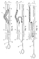
- Fig. 1a shows a Velcro closure 1 provided with a set 2 of a first surface 3 and a second surface 4.
- the first surface 3 and the second surface 4 each have a front side 5.
- the front sides 5 stick, thereby closing the Velcro closure 1.
- Such surfaces 3, 4 of a Velcro closure 1 are known per se.
- the front side 5 of the first surface 3 is provided with flexible hooks and the front side 5 of the second surface 4 is provided with loops.
- the second surface 4 will be provided on a part 8 to be closed using the Velcro closure 1.
- the second surface 4 with loops 7 usually comprises a ribbon 9 sewed onto the part 8 to be closed at positions 10.
- the first surface 3 is of bendable design and provided with a first longitudinal edge 11 connected, for instance by means of yarn 12, to the pulling part 13.
- the first surface 3 is further provided with a second longitudinal edge 14 located substantially opposite the first longitudinal edge 11.
- the first surface 3 and the pulling part 13 are included in a hem 15.
- the hem 15 is provided with a recess 16 for being able to place the first surface 3 with a normal to the front side 5 of the first surface 3 directed outwards.
- the second longitudinal edge 14 of the first surface 3 is connected, for instance by yarn 12, to the hem 15, preferably on an inside 17.
- the hem is provided with a first open end 18 and the pulling part 13 projects outside this first open end 18.
- the pulling part 13 When the pulling part 13 is pulled in a direction resulting in the first longitudinal edge 11 changing position in relation to the second longitudinal edge 14, the second longitudinal edge 14 forms an axis in relation to which the first surface 3 moves.
- Longitudinal edge 14 can, in a manner of speaking, be seen as a "flagpole” from which the first surface 3 hangs like a “flag'. In this metaphor, this "flag" is connected at a free end to the pulling part 13 which partly determines the arrangement of the "flag".
- Fig. 1b shows an initial stage of the opening of the Velcro closure 1.
- the pulling part 13 has been pulled at the first open end 18 in the direction of arrow P. This reduces the distance between the first longitudinal edge 11 and the second longitudinal edge 14 of the first surface 3.
- the first surface 3 will usually form a fold 19 projecting through the recess 16.
- the second surface 4 connected on the front side 5 to the first surface 3 will initially fold along with the first surface 3.
- the first surface 3 will then usually assume a horseshoe shape 20.
- the first surface 3 has the shape of an elongated S 21 and is located between the inside 17 of the hem 15 and the pulling part 13.
- the Velcro closure 1 is completely opened now.
- the part 8 is completely loose on the hem 15. Also, it is no longer possible for the part 8 to unintentionally close the Velcro closure, since the first surface 3 is retained between the inside 17 of the hem 15 and the pulling part 13.
- the front side 5 of the first surface 3 is remote from the front side 5 of the second surface 4. The part 8 can be removed without any problems.
- the pulling part 13 has to be pulled in the direction of arrow T. It is evident that, when completely pulling back the pulling part 13, the first surface 3 is again placed back into the recess 16 with a normal to the front side 5 of the first surface 3 directed outwards, so that the hooks 6 can again couple to the loops 7 of the front side 5 of the second surface 4 located above the recess 16. Once the Velcro closure is opened completely, the part 8 can of course be removed.
- the hem 15 is preferably further provided with a second open end (not shown) remote from the first open end 18 and the pulling part 13 projects outside the second open end.
- the pulling part 13 is preferably designed as a strip.
- the pulling part 13 and hem 15 are preferably manufactured from a sheet-shaped material having a low friction coefficient.
- the hem 15 will be provided on a garment of which the position is preserved by the body in the garment. When the garment is provided freely movably around the body, it is possible for the hem 15 to move along in the direction of the pulling force exerted on the pulling part 13.
- the hem 15 can be provided at the first open end 18 and/or near the second open end (not shown) with a grip 29 to be able to pull the hem 15 tight when pulling the pulling part 13.
- the first part is provided with a tubular channel 15, with the pulling element 13 extending in a longitudinal direction of the channel 15 and at least one flexible sheet of Velcro material 3 being, on the one hand, connected to the pulling element 13 at a first position 11 and being, on the other hand, connected to the tubular channel 15 at a second position 14, with the first and second position being separated from each other in a longitudinal direction of the channel 15, with the channel 15 being further provided with at least one opening 16 in which, in closed condition of the Velcro closure, at least a part of the sheet of Velcro material 3 is located, while the Velcro closure can be opened by moving the pulling element 13 from the closed condition of the closure in relation to the channel 15 in the longitudinal direction of the channel 15 from the first position 11 to the second position 14.
- the first part A comprises the hem 15, the pulling part 13 and the surface 3 and the second part B comprises the part 8 to be closed by the Velcro closure and the surface 4.
- the channel 15 is provided with a plurality of openings 16 separated from each other in the longitudinal direction of the channel 15 and a plurality of sheets of Velcro material 3, 4 connected to the pulling element 13 at first positions 11 and connected to the channel 15 at second positions 14 and while, in closed condition of the Velcro closure, at least a part of each of the sheets of Velcro material 3 are in one of the openings 16 of the tubular channel 15 respectively, and the Velcro closure can be opened by moving the pulling element 13 from the closed condition of the closure in relation to the channel 15 in the longitudinal direction of the channel 15 from the first position 11 to the second position 14.
- Fig. 2a shows a second embodiment of a Velcro closure according to the invention.
- the Velcro closure is provided with a plurality of sets 2.
- the sets 2 are included in a row extending in a longitudinal direction of the pulling part 13.
- Each first longitudinal edge 11 is connected to the pulling part 13 and each second longitudinal edge 14 is connected to the hem 15.
- each second longitudinal edge 14 is connected to an inside 17 of the hem.
- the recesses 16 are provided between the first open end 18 and the second open end (not shown) of the hem 15.
- the second surfaces 4 are provided in correspondence with the recesses 16. The working of the Velcro closure 1 shown in Fig.
- FIG. 2a is analogous to the working as shown in the Figs. 1a through 1d .
- the only difference between the embodiment of the Velcro closure shown in the Figs. 1a through 1d and the embodiment of the Velcro closure 1 shown in the Figs. 2a and 2b is the use of a plurality of sets 2 arranged in a row.
- a first surface 3 coupled to a second surface 4 will uncouple.
- the Velcro closure will open at each recess 16.
- the situation will change to a situation as diagrammatically shown in Fig. 2b .
- the Velcro closure 1 can be opened at each recess 16. It is not necessary that the Velcro closure 1 be opened at each recess 16 separately.
- the recesses 16 can, for instance, be designed much larger than is minimally required to bring a largest possible part of the front side 5 of the first surface 3 in contact with the second surface 4 through the recess 16.
- the recesses 16 can also be designed smaller than the size of the first surface 3.
- the first surface 3 does not need to be completely provided with hooks 6. It is possible that no hooks are provided near the first and/or the second longitudinal edge 11, 14. It is also possible that the hem 15 is completely provided with recesses 16 between the positions where the second longitudinal edge 14 is connected to the inside 17 of the hem 15.
- first surfaces 3 are provided with hooks
- second surfaces 4 it is also possible for the second surfaces 4 to be provided with hooks and the first surfaces 3 to be provided with loops.
- Hem 15 can be formed in many ways. For instance, separate layers can together form the hem 15, but it is also possible for the hem to comprise an edge which is folded back.
- the pulling part 13 comprises a relatively rigid part so that, from one of the open ends of the hem 15, the first surfaces 3 can be uncoupled from the second surfaces 4 by means of, for instance, a pulling force exerted on the more rigid pulling part 13 and that the first surfaces 3 can be placed back into the recesses 16 with a normal to the front side 5 of the first surface 3 directed outwards by pushing the pulling part 13 back into the hem 15.
- the hem 15 is pulled to move the pulling part 13 in relation to the hem 15.
- the second surfaces 4 can be included in a continuous strip of material.
- the Velcro closure 1 can also be manufactured and marketed without the part 8 with the second surfaces 4.
- the Velcro closure is suitable for a plurality of uses. Examples of these would be a closure for garments, a closure for a bag, a closure for a cover, and for instance a closure for a tent.
- the Velcro closure can be particularly useful when it is provided as a temporary closure of a dressing aid which is, at least in use, substantially tubular for, for instance, compression stockings and compression pantyhoses.
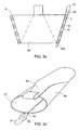
- Fig. 3a shows a partly sheet-shaped material 25 provided with two closing strips for forming a tubular covering as, for instance, shown in Fig. 3b .
- One of the closing strips is designed as a part 8 as shown in the Figs. 1a through 1d and the Figs. 2a and 2b .
- the other closing strip is shown as a hem 15 in which a pulling part 13 with first surfaces 3 is included.
- a user puts a tarsal bone part through opening 27 of the covering 26.
- the compression stockings and compression pantyhoses can easily be fitted around the sheet-shaped material having a low friction coefficient.
- the sheet-shaped covering 26 has to be removed from the tarsal bone part.
- pulling part 13 is pulled so that the Velcro closure is opened in a manner as described hereinabove.
- the covering 26 can now be pulled away from the tarsal bone part so that the compression stockings and compression pantyhoses fit directly to the tarsal bone part.
- the hem 15 is provided with a grip 29 to be able to pull the hem 15 tight when pulling the pulling part 13. This is especially necessary when the pulling part 13 has to be pulled back using the part 13a.
- Velcro closure 1 is not limited to a dressing aid as shown in the Figs. 3a and 3b .
- Dressing aids as described in WO 95/02980 can be provided with a Velcro closure according to the invention.
- Such a Velcro closure has many variations as described hereinabove.
Landscapes
- Packaging Of Annular Or Rod-Shaped Articles, Wearing Apparel, Cassettes, Or The Like (AREA)
- Socks And Pantyhose (AREA)
- Details Of Garments (AREA)
- Gripping Jigs, Holding Jigs, And Positioning Jigs (AREA)
- Joining Of Building Structures In Genera (AREA)
- Clamps And Clips (AREA)
- Bag Frames (AREA)
- Slide Fasteners (AREA)
- Media Introduction/Drainage Providing Device (AREA)
Claims (14)
- Klettverschluss, der mit einem ersten Teil (A) und einem zweiten Teil (B) bereitgestellt ist, worin der ersten Teil (A) und der zweite Teil (B) jeweils mit Haken- und Ösen-Material (3, 4) bereitgestellt ist, um den ersten Teil (A) und den zweiten Teil (B) lösbar aneinander zu befestigen, worin der Verschluss weiterhin mit einem Ziehelement (13) bereitgestellt ist, um den Verschluss zu öffnen, dadurch gekennzeichnet, dass der erste Teil (A) mit einem als Saum (15) ausgebildeten rohrförmigen Kanal bereitgestellt ist, wobei sich das Ziehelement (13) in der Längsrichtung des Saums (15) erstreckt und wobei mindestens eine flexible Bahn von Haken- und Ösen-Material (3) einerseits an einer ersten Kante (11) mit dem Ziehelement (13) verbunden ist, und andererseits an einer zweiten Kante (14) mit dem rohrförmigen Kanal (15) verbunden ist, worin die erste und zweite Kante (11, 14) voneinander in der Längsrichtung des Kanals (15) getrennt sind, worin der Kanal (15) weiterhin mit mindestens einer Öffnung (16) bereitgestellt ist, in der im geschlossenen Zustand des Klettverschlusses mindestens ein Teil der mindestens einen Bahn von Haken- und Ösen-Material (3) angeordnet ist, worin das Ziehelement (13) in der Längsrichtung des Kanals (15) von der ersten Kante (11) zur zweiten Kante (14) bewegt werden kann, um den Klettverschluss von dem geschlossenen Zustand des Verschlusses in Bezug auf den Saum (15) zu öffnen.
- Klettverschluss nach Anspruch 1, dadurch gekennzeichnet, dass der Kanal (15) mit mehreren Öffnungen (16) bereitgestellt ist, die voneinander in der Längsrichtung des Kanals (15) getrennt sind und mit mehreren Bahnen von Haken- und Ösen-Material (3, 4), die an ersten Kanten (11) mit dem Ziehelement (13) verbunden und an zweiten Kanten (14) mit dem Kanal (15) verbunden sind, und worin in einem geschlossenen Zustand des Klettverschlusses zumindest ein Teil von jeder der Bahnen von Haken- und Ösen-Material (3) jeweils in einer der Öffnungen (16) des rohrförmigen Kanals (15) angeordnet ist, wobei der Klettverschluss durch Bewegen des Ziehelements (13) von dem geschlossenen Zustand des Verschlusses in Bezug auf den Kanal (15) in der Längsrichtung des Kanals (15) von der ersten Kante (11) zu der zweiten Kante (14) geöffnet werden kann.
- Klettverschluss nach Anspruch 1, umfassend mindestens einen Satz einer ersten und einer zweiten Oberfläche des Haken- und Ösen-Materials (3, 4), wobei jede eine Vorderseite (5) aufweist, wobei die Vorderseiten (5) aneinander haften um den Verschluss zu schließen, wenn sie gegeneinander angeordnet bzw. platziert werden, wobei der Verschluss durch auseinander ziehen der Vorderseiten (5) geöffnet werden kann, die aneinander angeordnet wurden, worin mindestens die erste Oberfläche (3) eine biegsame Gestaltung aufweist und mit der ersten Kante (11) bereitgestellt ist, die mit dem Ziehelement verbunden ist, das durch das Ziehteil (13) gebildet wird, worin die erste Oberfläche (3) mit der zweiten Kante (14) einer festgelegten Gestaltung bereitgestellt ist, die im Wesentlichen gegenüber der ersten Kante (11) so angeordnet ist, dass die zweite Kante (14) eine Achse in Bezug auf die Richtung bildet, in die sich die erste Oberfläche (8) bewegt, wenn das Ziehteil (13) in eine Richtung gezogen wird, was die erste Kante (11) zu einer Positionsänderung in Bezug auf die zweite Kante (14) zwingt, dadurch gekennzeichnet, dass das Ziehelement (13) und die erste Oberfläche (3) in dem rohrförmigen Kanal (15) untergebracht sind, der mit der mindestens einen Öffnung bereitgestellt ist, die eine Aussparung (16) ist, angepasst, die erste Oberfläche (3) mit einer Normalen zu der Vorderseite (5) der ersten Oberfläche (3), die nach außen gerichtet ist, anzuordnen, und ein erstes offenes Ende (18), wobei das Zugteil (13) außerhalb des ersten offenen Endes (18) vorragt und die zweite Kante (14) ist mit dem Saum (15) fest verbunden ist.
- Klettverschluss nach Anspruch 3, dadurch gekennzeichnet, dass der Saum (15) weiterhin mit einem zweiten offenen Ende bereitgestellt ist, das von dem ersten offenen Ende und dem Ziehteil (13) entfernt liegt und ebenfalls außerhalb des zweiten offenen Endes vorragt.
- Klettverschluss nach Anspruch 3 oder 4, dadurch gekennzeichnet, dass das Ziehteil (13) als Streifen gestaltet ist.
- Klettverschluss nach einem der vorstehenden Ansprüche 3 bis 5, dadurch gekennzeichnet, dass der Klettverschluss mit einer Reihe von mehreren Sätzen (2) bereitgestellt ist, wobei sich die Reihe in der Längsrichtung des Ziehteils (13) erstreckt.
- Klettverschluss nach Anspruch 6, dadurch gekennzeichnet, dass die Aussparungen (16) in Übereinstimmung mit den Sätzen zwischen dem ersten offenen Ende (18) und dem zweiten offenen Ende des Saums (15) bereitgestellt sind.
- Klettverschluss nach Anspruch 7. dadurch gekennzeichnet, dass die zweiten Oberflächen (4) in Übereinstimmung mit den Aussparungen (16) an einem zu schließenden Teil (8) unter Verwendung des Klettverschlusses bereitgestellt sind.
- Klettverschluss nach einem der vorstehenden Ansprüche 3 bis 8, dadurch gekennzeichnet, dass das Ziehteil (13) und der Saum (15) aus einem Bahn-förmigen Material hergestellt sind, das einen niedrigen Reibungswiderstand aufweist.
- Klettverschluss nach einem der vorstehenden Ansprüche 3 bis 9, dadurch gekennzeichnet, dass der Saum (15) zumindest nahe des ersten offenen Endes (18) mit einem Griff (29) bereitgestellt ist, um den Saum (15) zuzuziehen, wenn das Ziehteil (13) gezogen wird.
- Klettverschluss nach einem der vorstehenden Ansprüche 3 bis 10, dadurch gekennzeichnet, dass die erste Oberfläche (3) mit flexiblen Haken (6) und die zweite Oberfläche (4) mit Ösen (7) bereitgestellt sind.
- Klettverschluss nach einem der vorstehenden Ansprüche 3 bis 11, dadurch gekennzeichnet, dass der Klettverschluss als vorübergehender Verschluss einer Ankleidehilfe bereitgestellt ist, die, zumindest bei Verwendung, im Wesentlichen rohrförmig ist, beispielsweise für Stützstrümpfe und Stützstrumpfhosen.
- Klettverschluss nach Anspruch 3, dadurch gekennzeichnet, dass die zweite Kante (14) mit einer Innerseite des Saums (15) fest verbunden ist.
- Ankleidehilfe zum Anziehen von beispielsweise Stützstrümpfen und Stützstrumpfhosen, worin die Ankleidehilfe mindestens ein bahnförmiges Material mit zwei Verschlussstreifen umfasst, um eine rohrförmige Bedeckung zu bilden, worin mindestens eine der Verschlussleisten mit einem Klettverschluss gemäß Anspruch 13 bereitgestellt ist.
Applications Claiming Priority (3)
| Application Number | Priority Date | Filing Date | Title |
|---|---|---|---|
| NL1020559 | 2002-05-08 | ||
| NL1020559A NL1020559C2 (nl) | 2002-05-08 | 2002-05-08 | Klittenbandsluiting, een klittenbandaansluitstrook, en een aantrekhulp voor bijvoorbeeld compressiekousen en compressiepanties. |
| PCT/NL2003/000340 WO2003094648A1 (en) | 2002-05-08 | 2003-05-07 | Hook and lopp fastener, a hook and loop connecting strip, and a dressing aid for, for example, compression stockings and compression pantyhose |
Publications (2)
| Publication Number | Publication Date |
|---|---|
| EP1501386A1 EP1501386A1 (de) | 2005-02-02 |
| EP1501386B1 true EP1501386B1 (de) | 2010-07-07 |
Family
ID=29417496
Family Applications (1)
| Application Number | Title | Priority Date | Filing Date |
|---|---|---|---|
| EP03725883A Expired - Lifetime EP1501386B1 (de) | 2002-05-08 | 2003-05-07 | Haftverschluss und hilfsvorrichtung für einen verband, wie zum beispiel, kompressionsstrümpfe und kompressionsstrumpfhose |
Country Status (9)
| Country | Link |
|---|---|
| US (1) | US7051409B2 (de) |
| EP (1) | EP1501386B1 (de) |
| AT (1) | ATE472952T1 (de) |
| AU (1) | AU2003228144A1 (de) |
| DE (1) | DE60333273D1 (de) |
| DK (1) | DK1501386T3 (de) |
| ES (1) | ES2348520T3 (de) |
| NL (1) | NL1020559C2 (de) |
| WO (1) | WO2003094648A1 (de) |
Families Citing this family (5)
| Publication number | Priority date | Publication date | Assignee | Title |
|---|---|---|---|---|
| NL1020559C2 (nl) | 2002-05-08 | 2003-11-11 | Arion Internat B V | Klittenbandsluiting, een klittenbandaansluitstrook, en een aantrekhulp voor bijvoorbeeld compressiekousen en compressiepanties. |
| NL2001400C2 (nl) * | 2008-03-25 | 2009-09-28 | Arion Internat B V | Hulpmiddel voor het uittrekken van elastische kousen. |
| US9119444B2 (en) * | 2009-05-01 | 2015-09-01 | Chittaranjan Narandas Nirmel | Versatile hook-and-loop fastener system |
| US10219954B2 (en) | 2016-06-15 | 2019-03-05 | Gayla Al-Arab | Medical compression garment and donning method |
| NL1043010B1 (en) * | 2018-09-25 | 2020-05-29 | Westwood Holding B V | Aid device for elastic support stockings |
Family Cites Families (8)
| Publication number | Priority date | Publication date | Assignee | Title |
|---|---|---|---|---|
| US4399595A (en) * | 1981-02-11 | 1983-08-23 | John Yoon | Magnetic closure mechanism |
| DE3229504C2 (de) * | 1982-08-07 | 1986-07-17 | Autoflug Gmbh, 2084 Rellingen | Packhüllen-Verschlußvorrichtung |
| FR2547488B1 (fr) * | 1983-06-17 | 1985-11-22 | Petit Sarl | Dispositif de fermeture a ruban auto-agrippant |
| CA1303297C (en) * | 1988-07-29 | 1992-06-16 | David Norbert Schreiner | Garment with hook-and-loop fasteners and sheath or pocket therefor |
| NL9301304A (nl) | 1993-07-23 | 1995-02-16 | Varitex Nv | Hulpmiddel voor het aantrekken van therapeutische elastische kousen. |
| NL1000925C2 (nl) | 1995-08-03 | 1997-02-04 | Arion Int Bv | Hulpmiddel voor het aantrekken van elastische kousen met gesloten teenstuk. |
| US5731056A (en) * | 1996-06-11 | 1998-03-24 | Mcdonnell Douglas Helicopter Company | Rigid structure attachment using hook and loop fasteners |
| NL1020559C2 (nl) | 2002-05-08 | 2003-11-11 | Arion Internat B V | Klittenbandsluiting, een klittenbandaansluitstrook, en een aantrekhulp voor bijvoorbeeld compressiekousen en compressiepanties. |
-
2002
- 2002-05-08 NL NL1020559A patent/NL1020559C2/nl not_active IP Right Cessation
-
2003
- 2003-05-07 EP EP03725883A patent/EP1501386B1/de not_active Expired - Lifetime
- 2003-05-07 AU AU2003228144A patent/AU2003228144A1/en not_active Abandoned
- 2003-05-07 ES ES03725883T patent/ES2348520T3/es not_active Expired - Lifetime
- 2003-05-07 WO PCT/NL2003/000340 patent/WO2003094648A1/en not_active Ceased
- 2003-05-07 DE DE60333273T patent/DE60333273D1/de not_active Expired - Lifetime
- 2003-05-07 AT AT03725883T patent/ATE472952T1/de active
- 2003-05-07 DK DK03725883.7T patent/DK1501386T3/da active
-
2004
- 2004-11-05 US US10/982,527 patent/US7051409B2/en not_active Expired - Fee Related
Also Published As
| Publication number | Publication date |
|---|---|
| DE60333273D1 (de) | 2010-08-19 |
| ATE472952T1 (de) | 2010-07-15 |
| EP1501386A1 (de) | 2005-02-02 |
| NL1020559C2 (nl) | 2003-11-11 |
| US20050091804A1 (en) | 2005-05-05 |
| WO2003094648A1 (en) | 2003-11-20 |
| AU2003228144A1 (en) | 2003-11-11 |
| DK1501386T3 (da) | 2010-11-01 |
| ES2348520T3 (es) | 2010-12-07 |
| US7051409B2 (en) | 2006-05-30 |
Similar Documents
| Publication | Publication Date | Title |
|---|---|---|
| USD907922S1 (en) | Bunker gear storage bag | |
| US9723882B2 (en) | Article of apparel convertible to a sleeping bag | |
| US20150027835A1 (en) | Hard luggage case with changeable case portion | |
| USD863980S1 (en) | Reclosable slider zipper flexible bag | |
| EP1232955A3 (de) | Beutel mit eingebauter Verschlusslasche | |
| US7021853B2 (en) | Body with outer detachable pouch | |
| CN112911957A (zh) | 带一体式插入件的袖子 | |
| EP1501386B1 (de) | Haftverschluss und hilfsvorrichtung für einen verband, wie zum beispiel, kompressionsstrümpfe und kompressionsstrumpfhose | |
| CA2806890C (en) | Ostomy pouch apparatus with closable opening | |
| US5836058A (en) | Safety release zipper | |
| JP3136822U (ja) | ランドセルカバーのセット | |
| CN212520842U (zh) | 一种口袋可拆卸的外套 | |
| CN206314621U (zh) | 一种具有耳部保暖功能的拉链开口式口罩 | |
| US20210236354A1 (en) | Individual first aid kit with insert | |
| US20130253575A1 (en) | Apparatus for relieving neck pressure | |
| CN106579596B (zh) | 一种具有耳部保暖功能的拉链开口式口罩 | |
| US6842910B1 (en) | Convertible cape | |
| JP3226859U (ja) | ウエットスーツ | |
| CN206978809U (zh) | 一种护腿 | |
| GB2366724A (en) | A duvet cover | |
| CN218635361U (zh) | 一种警示层拆卸式户外工作服 | |
| CN218683503U (zh) | 可穿着睡袋 | |
| CN215228532U (zh) | 一种毛发固定器 | |
| CN214727639U (zh) | 一种笔记本 | |
| CN214230244U (zh) | 一种收纳包 |
Legal Events
| Date | Code | Title | Description |
|---|---|---|---|
| PUAI | Public reference made under article 153(3) epc to a published international application that has entered the european phase |
Free format text: ORIGINAL CODE: 0009012 |
|
| 17P | Request for examination filed |
Effective date: 20041104 |
|
| AK | Designated contracting states |
Kind code of ref document: A1 Designated state(s): AT BE BG CH CY CZ DE DK EE ES FI FR GB GR HU IE IT LI LU MC NL PT RO SE SI SK TR |
|
| AX | Request for extension of the european patent |
Extension state: AL LT LV MK |
|
| DAX | Request for extension of the european patent (deleted) | ||
| 17Q | First examination report despatched |
Effective date: 20081105 |
|
| RTI1 | Title (correction) |
Free format text: HOOK AND LOOP FASTENER AND A DRESSING AID FOR, FOR EXAMPLE, COMPRESSION STOCKINGS AND COMPRESSION PANTYHOSE |
|
| GRAP | Despatch of communication of intention to grant a patent |
Free format text: ORIGINAL CODE: EPIDOSNIGR1 |
|
| GRAS | Grant fee paid |
Free format text: ORIGINAL CODE: EPIDOSNIGR3 |
|
| GRAA | (expected) grant |
Free format text: ORIGINAL CODE: 0009210 |
|
| RAP1 | Party data changed (applicant data changed or rights of an application transferred) |
Owner name: ARION HOLDING B.V. |
|
| AK | Designated contracting states |
Kind code of ref document: B1 Designated state(s): AT BE BG CH CY CZ DE DK EE ES FI FR GB GR HU IE IT LI LU MC NL PT RO SE SI SK TR |
|
| REG | Reference to a national code |
Ref country code: GB Ref legal event code: FG4D |
|
| REG | Reference to a national code |
Ref country code: CH Ref legal event code: EP |
|
| REG | Reference to a national code |
Ref country code: IE Ref legal event code: FG4D |
|
| REF | Corresponds to: |
Ref document number: 60333273 Country of ref document: DE Date of ref document: 20100819 Kind code of ref document: P |
|
| REG | Reference to a national code |
Ref country code: CH Ref legal event code: NV Representative=s name: E. BLUM & CO. AG PATENT- UND MARKENANWAELTE VSP |
|
| REG | Reference to a national code |
Ref country code: SE Ref legal event code: TRGR |
|
| REG | Reference to a national code |
Ref country code: NL Ref legal event code: T3 |
|
| REG | Reference to a national code |
Ref country code: DK Ref legal event code: T3 |
|
| REG | Reference to a national code |
Ref country code: ES Ref legal event code: FG2A Effective date: 20101124 |
|
| PG25 | Lapsed in a contracting state [announced via postgrant information from national office to epo] |
Ref country code: SI Free format text: LAPSE BECAUSE OF FAILURE TO SUBMIT A TRANSLATION OF THE DESCRIPTION OR TO PAY THE FEE WITHIN THE PRESCRIBED TIME-LIMIT Effective date: 20100707 |
|
| PG25 | Lapsed in a contracting state [announced via postgrant information from national office to epo] |
Ref country code: PT Free format text: LAPSE BECAUSE OF FAILURE TO SUBMIT A TRANSLATION OF THE DESCRIPTION OR TO PAY THE FEE WITHIN THE PRESCRIBED TIME-LIMIT Effective date: 20101108 Ref country code: BG Free format text: LAPSE BECAUSE OF FAILURE TO SUBMIT A TRANSLATION OF THE DESCRIPTION OR TO PAY THE FEE WITHIN THE PRESCRIBED TIME-LIMIT Effective date: 20101007 Ref country code: CY Free format text: LAPSE BECAUSE OF FAILURE TO SUBMIT A TRANSLATION OF THE DESCRIPTION OR TO PAY THE FEE WITHIN THE PRESCRIBED TIME-LIMIT Effective date: 20100707 |
|
| PG25 | Lapsed in a contracting state [announced via postgrant information from national office to epo] |
Ref country code: GR Free format text: LAPSE BECAUSE OF FAILURE TO SUBMIT A TRANSLATION OF THE DESCRIPTION OR TO PAY THE FEE WITHIN THE PRESCRIBED TIME-LIMIT Effective date: 20101008 |
|
| PLBE | No opposition filed within time limit |
Free format text: ORIGINAL CODE: 0009261 |
|
| STAA | Information on the status of an ep patent application or granted ep patent |
Free format text: STATUS: NO OPPOSITION FILED WITHIN TIME LIMIT |
|
| PG25 | Lapsed in a contracting state [announced via postgrant information from national office to epo] |
Ref country code: CZ Free format text: LAPSE BECAUSE OF FAILURE TO SUBMIT A TRANSLATION OF THE DESCRIPTION OR TO PAY THE FEE WITHIN THE PRESCRIBED TIME-LIMIT Effective date: 20100707 Ref country code: RO Free format text: LAPSE BECAUSE OF FAILURE TO SUBMIT A TRANSLATION OF THE DESCRIPTION OR TO PAY THE FEE WITHIN THE PRESCRIBED TIME-LIMIT Effective date: 20100707 Ref country code: EE Free format text: LAPSE BECAUSE OF FAILURE TO SUBMIT A TRANSLATION OF THE DESCRIPTION OR TO PAY THE FEE WITHIN THE PRESCRIBED TIME-LIMIT Effective date: 20100707 Ref country code: SK Free format text: LAPSE BECAUSE OF FAILURE TO SUBMIT A TRANSLATION OF THE DESCRIPTION OR TO PAY THE FEE WITHIN THE PRESCRIBED TIME-LIMIT Effective date: 20100707 |
|
| 26N | No opposition filed |
Effective date: 20110408 |
|
| REG | Reference to a national code |
Ref country code: DE Ref legal event code: R097 Ref document number: 60333273 Country of ref document: DE Effective date: 20110408 |
|
| PG25 | Lapsed in a contracting state [announced via postgrant information from national office to epo] |
Ref country code: MC Free format text: LAPSE BECAUSE OF NON-PAYMENT OF DUE FEES Effective date: 20110531 |
|
| REG | Reference to a national code |
Ref country code: IE Ref legal event code: MM4A |
|
| PG25 | Lapsed in a contracting state [announced via postgrant information from national office to epo] |
Ref country code: IE Free format text: LAPSE BECAUSE OF NON-PAYMENT OF DUE FEES Effective date: 20110507 |
|
| PGFP | Annual fee paid to national office [announced via postgrant information from national office to epo] |
Ref country code: BE Payment date: 20120524 Year of fee payment: 10 Ref country code: FI Payment date: 20120511 Year of fee payment: 10 Ref country code: GB Payment date: 20120522 Year of fee payment: 10 Ref country code: SE Payment date: 20120522 Year of fee payment: 10 |
|
| PGFP | Annual fee paid to national office [announced via postgrant information from national office to epo] |
Ref country code: IT Payment date: 20120528 Year of fee payment: 10 |
|
| PGFP | Annual fee paid to national office [announced via postgrant information from national office to epo] |
Ref country code: ES Payment date: 20120525 Year of fee payment: 10 |
|
| PGFP | Annual fee paid to national office [announced via postgrant information from national office to epo] |
Ref country code: AT Payment date: 20120511 Year of fee payment: 10 |
|
| PG25 | Lapsed in a contracting state [announced via postgrant information from national office to epo] |
Ref country code: LU Free format text: LAPSE BECAUSE OF NON-PAYMENT OF DUE FEES Effective date: 20110507 |
|
| PG25 | Lapsed in a contracting state [announced via postgrant information from national office to epo] |
Ref country code: TR Free format text: LAPSE BECAUSE OF FAILURE TO SUBMIT A TRANSLATION OF THE DESCRIPTION OR TO PAY THE FEE WITHIN THE PRESCRIBED TIME-LIMIT Effective date: 20100707 |
|
| PG25 | Lapsed in a contracting state [announced via postgrant information from national office to epo] |
Ref country code: HU Free format text: LAPSE BECAUSE OF FAILURE TO SUBMIT A TRANSLATION OF THE DESCRIPTION OR TO PAY THE FEE WITHIN THE PRESCRIBED TIME-LIMIT Effective date: 20100707 |
|
| BERE | Be: lapsed |
Owner name: ARION HOLDING B.V. Effective date: 20130531 |
|
| REG | Reference to a national code |
Ref country code: SE Ref legal event code: EUG |
|
| REG | Reference to a national code |
Ref country code: AT Ref legal event code: MM01 Ref document number: 472952 Country of ref document: AT Kind code of ref document: T Effective date: 20130531 |
|
| GBPC | Gb: european patent ceased through non-payment of renewal fee |
Effective date: 20130507 |
|
| PG25 | Lapsed in a contracting state [announced via postgrant information from national office to epo] |
Ref country code: AT Free format text: LAPSE BECAUSE OF NON-PAYMENT OF DUE FEES Effective date: 20130531 Ref country code: SE Free format text: LAPSE BECAUSE OF NON-PAYMENT OF DUE FEES Effective date: 20130508 |
|
| PG25 | Lapsed in a contracting state [announced via postgrant information from national office to epo] |
Ref country code: FI Free format text: LAPSE BECAUSE OF NON-PAYMENT OF DUE FEES Effective date: 20130507 Ref country code: BE Free format text: LAPSE BECAUSE OF NON-PAYMENT OF DUE FEES Effective date: 20130531 Ref country code: IT Free format text: LAPSE BECAUSE OF NON-PAYMENT OF DUE FEES Effective date: 20130507 |
|
| PG25 | Lapsed in a contracting state [announced via postgrant information from national office to epo] |
Ref country code: GB Free format text: LAPSE BECAUSE OF NON-PAYMENT OF DUE FEES Effective date: 20130507 |
|
| REG | Reference to a national code |
Ref country code: ES Ref legal event code: FD2A Effective date: 20150709 |
|
| PG25 | Lapsed in a contracting state [announced via postgrant information from national office to epo] |
Ref country code: ES Free format text: LAPSE BECAUSE OF NON-PAYMENT OF DUE FEES Effective date: 20130508 |
|
| REG | Reference to a national code |
Ref country code: FR Ref legal event code: PLFP Year of fee payment: 14 |
|
| REG | Reference to a national code |
Ref country code: FR Ref legal event code: PLFP Year of fee payment: 15 |
|
| PGFP | Annual fee paid to national office [announced via postgrant information from national office to epo] |
Ref country code: NL Payment date: 20170426 Year of fee payment: 15 |
|
| PGFP | Annual fee paid to national office [announced via postgrant information from national office to epo] |
Ref country code: DE Payment date: 20170523 Year of fee payment: 15 Ref country code: DK Payment date: 20170519 Year of fee payment: 15 Ref country code: CH Payment date: 20170519 Year of fee payment: 15 |
|
| REG | Reference to a national code |
Ref country code: FR Ref legal event code: PLFP Year of fee payment: 16 |
|
| REG | Reference to a national code |
Ref country code: DE Ref legal event code: R119 Ref document number: 60333273 Country of ref document: DE |
|
| REG | Reference to a national code |
Ref country code: CH Ref legal event code: PL |
|
| REG | Reference to a national code |
Ref country code: DK Ref legal event code: EBP Effective date: 20180531 Ref country code: NL Ref legal event code: MM Effective date: 20180601 |
|
| PG25 | Lapsed in a contracting state [announced via postgrant information from national office to epo] |
Ref country code: CH Free format text: LAPSE BECAUSE OF NON-PAYMENT OF DUE FEES Effective date: 20180531 Ref country code: LI Free format text: LAPSE BECAUSE OF NON-PAYMENT OF DUE FEES Effective date: 20180531 |
|
| PG25 | Lapsed in a contracting state [announced via postgrant information from national office to epo] |
Ref country code: NL Free format text: LAPSE BECAUSE OF NON-PAYMENT OF DUE FEES Effective date: 20180601 Ref country code: DE Free format text: LAPSE BECAUSE OF NON-PAYMENT OF DUE FEES Effective date: 20181201 |
|
| PG25 | Lapsed in a contracting state [announced via postgrant information from national office to epo] |
Ref country code: DK Free format text: LAPSE BECAUSE OF NON-PAYMENT OF DUE FEES Effective date: 20180531 |
|
| PGFP | Annual fee paid to national office [announced via postgrant information from national office to epo] |
Ref country code: FR Payment date: 20210520 Year of fee payment: 19 |
|
| PG25 | Lapsed in a contracting state [announced via postgrant information from national office to epo] |
Ref country code: FR Free format text: LAPSE BECAUSE OF NON-PAYMENT OF DUE FEES Effective date: 20220531 |