EP1501291A2 - Videobildprojektor - Google Patents
Videobildprojektor Download PDFInfo
- Publication number
- EP1501291A2 EP1501291A2 EP04017220A EP04017220A EP1501291A2 EP 1501291 A2 EP1501291 A2 EP 1501291A2 EP 04017220 A EP04017220 A EP 04017220A EP 04017220 A EP04017220 A EP 04017220A EP 1501291 A2 EP1501291 A2 EP 1501291A2
- Authority
- EP
- European Patent Office
- Prior art keywords
- projector
- projection
- reflective
- mirror
- axis
- Prior art date
- Legal status (The legal status is an assumption and is not a legal conclusion. Google has not performed a legal analysis and makes no representation as to the accuracy of the status listed.)
- Withdrawn
Links
Images


Classifications
-
- G—PHYSICS
- G03—PHOTOGRAPHY; CINEMATOGRAPHY; ANALOGOUS TECHNIQUES USING WAVES OTHER THAN OPTICAL WAVES; ELECTROGRAPHY; HOLOGRAPHY
- G03B—APPARATUS OR ARRANGEMENTS FOR TAKING PHOTOGRAPHS OR FOR PROJECTING OR VIEWING THEM; APPARATUS OR ARRANGEMENTS EMPLOYING ANALOGOUS TECHNIQUES USING WAVES OTHER THAN OPTICAL WAVES; ACCESSORIES THEREFOR
- G03B21/00—Projectors or projection-type viewers; Accessories therefor
- G03B21/14—Details
- G03B21/28—Reflectors in projection beam
-
- H—ELECTRICITY
- H04—ELECTRIC COMMUNICATION TECHNIQUE
- H04N—PICTORIAL COMMUNICATION, e.g. TELEVISION
- H04N5/00—Details of television systems
- H04N5/74—Projection arrangements for image reproduction, e.g. using eidophor
- H04N5/7416—Projection arrangements for image reproduction, e.g. using eidophor involving the use of a spatial light modulator, e.g. a light valve, controlled by a video signal
- H04N5/7458—Projection arrangements for image reproduction, e.g. using eidophor involving the use of a spatial light modulator, e.g. a light valve, controlled by a video signal the modulator being an array of deformable mirrors, e.g. digital micromirror device [DMD]
-
- H—ELECTRICITY
- H04—ELECTRIC COMMUNICATION TECHNIQUE
- H04N—PICTORIAL COMMUNICATION, e.g. TELEVISION
- H04N9/00—Details of colour television systems
- H04N9/12—Picture reproducers
- H04N9/31—Projection devices for colour picture display, e.g. using electronic spatial light modulators [ESLM]
- H04N9/3141—Constructional details thereof
Definitions
- the present invention relates to a projector which projects an image to a screen.
- Projectors are utilized as means for a plurality of people to simultaneously share video information at, for example, small planning sessions, meetings, large conferences and seminars. That is, the projector is portable and enables all participants to simultaneously view the same material and understand its content. Thus, the projector serves in achieving efficient meetings and sessions or convincing presentations.
- US 2002/0024637 A1 proposes a projector in which a digital micromirror device (DMD: a registered trademark of Texas Instruments, Inc., of the United States) is used as a light modulating device.
- DMD digital micromirror device
- the DMD is a device in which a reflective surface is configured by a plurality of square micromirrors arranged in a matrix.
- Each micromirror has a diagonal pivot shaft, that is a pivot shaft with an inclination of 45 degrees with respect to an arranging direction of the mirror, and is configured to change its direction depending on whether it is turned on or off.
- illumination light and reflected light are arranged to enter/exit along a plane which is perpendicular to the pivot shaft of the micromirror, the reflected light is emitted in a different direction depending on whether the mirror is turned off (off position) or on (on position).
- a projection lens is disposed, for example, in a direction in which the reflected light is projected when the mirror is turned on such that the reflected light can be projected on a screen. Therefore, each of the micromirrors of such a DMD is adapted to correspond to a pixel, and each micromirror is turned on/off in accordance with a value of each pixel of an input image, thereby making it possible to configure a projector which projects an image corresponding to the input image.
- the projector disclosed in US 2002/0024637 A1 described above has the following configuration.
- Light emitted from a light source in led to an optical system for illumination via an integrator rod.
- the light emitted from the optical system for illumination has its light path bent by a total internal reflection (TIR) prism, and enters, as the illumination light, the DMD disposed on a DMD substrate.
- the reflected light (ON light) reflected by the DMD passes through the TIR prism and is projected to the screen by an optical system for projection.
- TIR total internal reflection
- the pivot shaft of each mirror of the DMD has an inclination of 45 degrees with respect to the arranging direction of the mirror as described above, the illumination light of the DMD needs to enter from a direction having an inclination of 45 degrees with respect to the arranging direction of the mirror of the DMD. Therefore, in the projector disclosed in US 2002/0024637 A1 described above, the DMD is mounted on the DMD substrate at an inclination of 45 degrees. The reason that the optical system for illumination which emits the illumination light are not inclined but the DMD is inclined as described above is to enable the projector to be stored in a small thin case. However, if the DMD is disposed with an inclination of 45 degrees as described above, the image projected to the screen is inclined at 45 degrees.
- a projection unit storing such a configuration is mounted on a projector base so that it can pivot 45 degrees on a rotation hinge around a shaft vertical to the DMD.
- the projection unit is inclined at 45 degrees so that an erect projection image is projected on the screen.
- US 2002/0180939 A1 discloses a projector having the following configuration of an optical system. That is, light emitted from a light source is condensed to an integrator rod via a color wheel. The light emitted from the integrator rod is led to a TIR prism by a plurality of mirrors, and is totally reflected by the TIR prism to illuminate the DMD. Thus, the DMD is illuminated from a required direction with a required incidence angle. The illumination light thus illuminating is then reflected by the DMD to perform light modulation. The light which has passed through the TIR prism after the light modulation is projected to a screen by an optical system for projection.
- the optical system for illumination uses a plurality of mirrors so that normal projection can be performed without disposing the DMD with inclination.
- the present invention has been attained in view of the foregoing points, and has an object of providing a projector capable of the normal projection without inclining the case storing the optical system or without using a complex optical system for illumination.
- a projector comprising:
- a projector comprising:
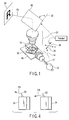
- a light source 10 an integrator rod 12, an optical system for illumination 14, a TIR prism 16, a DMD substrate 18, a DMD 20, and an optical system for projection 22, as in US 2002/0024637 A1 described above. That is, light emitted from the light source 10 is condensed on the integrator rod 12, led to the TIR prism 16 by the optical system for illumination 14, and totally reflected by the TIR prism 16, thereby illuminating the DMD 20 disposed on the DMD substrate 18.
- the DMD substrate 18 which is a support base surface on which mount the DMD 20 is disposed in the projector case 24 at a position substantially parallel with a surface on which the projector is placed, for example, a surface of a top plate of a table.
- the projector case 24 includes at least one case surface which includes an axis at an angle of 45 about degrees to both an X axis 26 and a Y axis 29 along which a plurality of micromirrors of the DMD 20 is arranged. This case surface is located substantially perpendicularly to the surface on which place the projector case 24 when the projector case 24 is placed on this surface.
- the projector according to the present embodiment further comprises a mirror 30 which bends a projection chief ray PB reflected at the center of the DMD 20 among chief rays in the optical system for projection 22.
- a reflective surface of the mirror 30 has a predetermined angle to the ray which is emitted from the optical system for illumination 14 and strikes the center of the DMD 20.
- the reflective surface of the mirror 30 includes a P shaft 32 parallel with any one (the X axis 26 in the illustrated example) of the X axis 26 and the Y axis 28 along which a plurality of micromirrors of the DMD 20 is arranged.
- the DMD 20 is mounted with an inclination in terms of planes of an entrance optical system and an exit optical system, but one shaft (P shaft 32) of the mirror 30 is adapted to the inclination of the DMD 20 such that a projection image 34 is normally projected.
- P shaft 32 the shaft of the mirror 30 is adapted to the inclination of the DMD 20 such that a projection image 34 is normally projected.
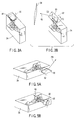
- this mirror 30 can pivot freely on the P shaft 32. Therefore, as shown in FIG. 2C to FIG. 4, the pivoting angle, that is, the inclination of this mirror 30, can be changed to adjust the projecting direction of the projection image 34.
- the reflective surface of the mirror 30 is disposed at a position substantially perpendicular to an optical axis of the optical system for projection 22 as shown in FIG. 3A, so that the mirror 30 serves as a lens cover. More specifically, the mirror 30 can serve to prevent lenses of the optical system for projection 22 from being flawed and dust from sticking to lens surfaces. It is to be noted that the mirror 30 is configured so that it can pivot 45 degrees on an axis (not shown) parallel to the optical axis of the optical system for projection 22. Therefore, in order to shift from a non-projecting state as shown in FIG. 3A to a projecting state as shown in FIG.
- the mirror 30 has a rectangular shape, and that the P shaft 32 is designed to be perpendicular to a long-side direction of the mirror 30. With such a mirror shape, the mirror 30 does not run out of the projector case 24 when projection is not performed.
- the mirror shape is not naturally limited to the rectangular shape.
- the mirror shape may be a planar shape whose dimension in a direction perpendicular to the P shaft 32 is long enough to completely cover an image to be projected when this image is reflected on the mirror surface, and may be, for example, elliptical.
- the support base surface for the DMD 20 of the DMD substrate 18 may be located on a surface in the projector case 24 including a line substantially parallel to a normal to a surface (generally a screen surface) on which the micromirrors of the DMD 20 by the optical system for projection 22 form an image.
- the projector case 24 includes at least one case surface which includes the axis at an angle of 45 degrees to both the X axis 26 and the Y axis 28 along which a plurality of micromirrors of the DMD 20 is arranged. This case surface is located substantially parallel to the surface on which place the projector case 24 when the projector case 24 is placed on this surface.
- the projecting direction is on a slant of 45 degrees.
- the projector case 24 is configured by a projector base unit 24A and a projector main unit 24B, as shown in FIG. 6.
- the support base surface for the DMD 20 of the DMD substrate 18 is disposed in the projector main unit 24B at a position substantially perpendicular to the surface on which the projector is placed.
- the projector main unit 24B is configured pivotally with respect to the projector base unit 24A.
- the projector main unit 24B is fixed by an unshown lock mechanism at a position pivoted from the projector base unit 24A so that the P shaft 32 of the mirror 30 is perpendicular to the surface on which the projector is placed when the projector is projecting.
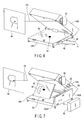
- an inlet 36 used to release heat in the projector main unit 24B is disposed on a surface opposite to the projector base unit 24A among surfaces constituting the projector main unit 24B.
- This inlet 36 exposes an opening which enables suction only when the projector main unit 24B is fixed at the position pivoted from the projector base unit 24A. This can prevent the entry of dust from the inlet 36 when projection is not performed.
- operation switches for an operator to control functions of the projector such as a power supply button 38 to control power supply to the projector and various operation buttons 40 to adjust color and brightness, are arranged on a surface opposite to the projector main unit 24B among surfaces constituting the projector base unit 24A.
- These operation switches are operable only when the projector main unit 24B is fixed at the position pivoted from the projector base unit 24A. Therefore, the operation switches cannot be operated inadvertently.
- the inlet 36 exposes the opening which enables suction, only when the projector main unit 24B is opened with respect to the projector base unit 24A, so that cooling can only be performed when it is opened.
- a signal line 42 and a power supply line 44 are configured to be connected to a surface vertical to the surface on which the projector is placed among the surfaces constituting the projector base unit 24A. That is, if the connection lines to the outside are connected on the side of the projector main unit 24B, the projection image 34 is displaced greatly on the screen surface, for example, when a force is applied to the connection lines even though the force is small. Thus, the connection lines are connected on the side of the projector main unit 24B as described above.
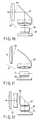
- a battery 46 can also be used instead of the power supply line 44 as shown in FIG. 7. In this case, by attaching the heavy battery 46 to the side of the projector base unit 24A, the center of gravity is lowered and stability is increased.
- an outlet 48 used to release heat in the projector main unit 24B may be disposed on a surface opposite to a surface 24A1 to which the battery 46 of the projector base unit 24A is attached among the surfaces constituting the projector main unit 24B.
- This outlet 48 exposes an opening which enables air discharge only when the projector main unit 24B is fixed at the position pivoted from the projector base unit 24A. This can prevent the entry of dust from the outlet 48 when projection is not performed.
- a depression 24A2 is provided in the surface 24A1 of the projector base unit 24A in accordance with a rise produced by the mirror 30.
- the projector base unit 24A may also be configured in such a manner that an operation panel 50 provided with the operation switches such as the power supply button 38 and the operation buttons 40 pivots to allow easier operation and to support the opened projector main unit 24B.
- the projection chief ray PB aligns with the optical axis of the optical system for projection 22.
- the DMD 20 may be disposed at a position shifted for a predetermined offset distance in a direction parallel to its micromirrors and perpendicular to the P shaft 32 so that the projection chief ray PB is inclined with respect to the optical axis of the optical system for projection 22. That is, a projection optical system central axis 52 is offset from a DMD central axis 54.
- the mirror 30 is disposed in the rear of the optical system for projection 22, but the present invention is not limited thereto.
- the mirror 30 may be disposed within a lens group of the optical system for projection 22 as shown in FIG. 10.
- one having a curved surface is used as the mirror 30 within such a projection lens group and may also serve as a lens.
- a rectangular prism 56 whose entrance plane and exit plane are formed by curved surfaces to serve as lenses may be disposed between the optical system for projection 22 and the DMD 20, as shown in FIG. 12.
- a DMD has been used as a reflective light modulating device in the embodiments described above, but the present invention is not limited to a DMD, and other reflective light modulating devices may also be used.
- the present invention is suitably used for a modulating device in which the optical system for illumination has to be disposed at a slant with respect to the arranging direction (X axis 26, Y axis 28) of the modulating device (of the micromirrors in the case of a DMD) as shown in FIG. 2A to FIG. 2C.
Landscapes
- Engineering & Computer Science (AREA)
- Multimedia (AREA)
- Signal Processing (AREA)
- Physics & Mathematics (AREA)
- General Physics & Mathematics (AREA)
- Projection Apparatus (AREA)
Applications Claiming Priority (2)
| Application Number | Priority Date | Filing Date | Title |
|---|---|---|---|
| JP2003278884A JP2005043739A (ja) | 2003-07-24 | 2003-07-24 | プロジェクタ |
| JP2003278884 | 2003-07-24 |
Publications (2)
| Publication Number | Publication Date |
|---|---|
| EP1501291A2 true EP1501291A2 (de) | 2005-01-26 |
| EP1501291A3 EP1501291A3 (de) | 2005-02-16 |
Family
ID=33487704
Family Applications (1)
| Application Number | Title | Priority Date | Filing Date |
|---|---|---|---|
| EP04017220A Withdrawn EP1501291A3 (de) | 2003-07-24 | 2004-07-21 | Videobildprojektor |
Country Status (3)
| Country | Link |
|---|---|
| US (1) | US7128425B2 (de) |
| EP (1) | EP1501291A3 (de) |
| JP (1) | JP2005043739A (de) |
Cited By (1)
| Publication number | Priority date | Publication date | Assignee | Title |
|---|---|---|---|---|
| CN103189793A (zh) * | 2010-11-02 | 2013-07-03 | 富士胶片株式会社 | 投影仪设备 |
Families Citing this family (14)
| Publication number | Priority date | Publication date | Assignee | Title |
|---|---|---|---|---|
| US7077528B1 (en) * | 2004-04-22 | 2006-07-18 | Raytheon Company | Digital projection display system with external light source |
| JP4017167B2 (ja) * | 2004-06-07 | 2007-12-05 | フジノン株式会社 | 投映表示装置 |
| TWI261462B (en) * | 2005-04-21 | 2006-09-01 | Optoma Corp | Optical projection apparatus |
| TWI307412B (en) * | 2005-07-21 | 2009-03-11 | Watonga Technology Inc | Projecting apparatus and image shift apparatus thereof |
| US8411194B2 (en) * | 2005-08-22 | 2013-04-02 | Texas Instruments Incorporated | Methods for combining camera and projector functions in a single device |
| JP4967307B2 (ja) * | 2005-10-24 | 2012-07-04 | セイコーエプソン株式会社 | プロジェクタ |
| US20070091452A1 (en) * | 2005-10-25 | 2007-04-26 | Scott Lerner | Projection system and method |
| JP2007286516A (ja) * | 2006-04-19 | 2007-11-01 | Sharp Corp | 投射型画像表示装置 |
| KR20090093666A (ko) * | 2008-02-29 | 2009-09-02 | 삼성전자주식회사 | 투사 광학 시스템 |
| JP5206067B2 (ja) * | 2008-03-28 | 2013-06-12 | セイコーエプソン株式会社 | 投射装置及び画像表示装置 |
| JP6738746B2 (ja) * | 2017-01-30 | 2020-08-12 | 株式会社日立エルジーデータストレージ | 映像投影装置 |
| JP6805981B2 (ja) * | 2017-07-04 | 2020-12-23 | コニカミノルタ株式会社 | 光学ユニット及びそれを備えたプロジェクター |
| CN210776142U (zh) * | 2019-08-30 | 2020-06-16 | 中强光电股份有限公司 | 投影装置 |
| CN114706262B (zh) * | 2021-12-15 | 2024-01-16 | 深圳市安华光电技术股份有限公司 | 一种投影光机及投影仪 |
Family Cites Families (15)
| Publication number | Priority date | Publication date | Assignee | Title |
|---|---|---|---|---|
| US5321450A (en) * | 1993-05-11 | 1994-06-14 | Proxima Corporation | Low profile liquid crystal projector and method of using same |
| US5639152A (en) * | 1996-06-11 | 1997-06-17 | Telex Communications, Inc. | Collapsible LCD projector |
| AT405471B (de) * | 1996-10-21 | 1999-08-25 | Jessl Rainer | System zur räumlichen bewegung des projektionsstrahls von optoelektronischen bildquellen mit korrektur des abbildungsfehlers |
| JP3319996B2 (ja) * | 1997-10-20 | 2002-09-03 | 株式会社日立製作所 | 映像表示機構及び映像表示装置 |
| US6190015B1 (en) * | 1999-08-05 | 2001-02-20 | Mustek Systems, Inc. | Liquid crystal display projector with a lens shading device capable shading and positioning lens |
| IT1308865B1 (it) * | 1999-11-05 | 2002-01-11 | Sim2 Multimedia Spa | Sistema ottico di illuminamento per videoproiettore. |
| US6712475B2 (en) * | 2000-08-31 | 2004-03-30 | Texas Instruments Incorporated | Housing and internal layout for compact SLM-based projector |
| JP3646658B2 (ja) * | 2001-03-01 | 2005-05-11 | セイコーエプソン株式会社 | 画像歪みの補正 |
| JP4126524B2 (ja) * | 2001-05-30 | 2008-07-30 | フジノン株式会社 | プロジェクタ装置 |
| AU2002365568A1 (en) * | 2001-11-28 | 2003-06-10 | 3M Innovative Properties Company | Tir prism for dmd projector |
| US6665048B2 (en) * | 2002-01-22 | 2003-12-16 | Creo Inc. | Method for imaging a continuously moving object |
| KR100441506B1 (ko) * | 2002-07-16 | 2004-07-23 | 삼성전자주식회사 | 영상투사장치 |
| JP2004279695A (ja) * | 2003-03-14 | 2004-10-07 | Nec Viewtechnology Ltd | 異物センサ回路付きプロジェクタ |
| KR20050004369A (ko) * | 2003-07-02 | 2005-01-12 | 윤준영 | 오버헤드프로젝터 |
| JP2005055812A (ja) * | 2003-08-07 | 2005-03-03 | Olympus Corp | プロジェクタ装置及びそれを組み込んだ机 |
-
2003
- 2003-07-24 JP JP2003278884A patent/JP2005043739A/ja active Pending
-
2004
- 2004-07-21 EP EP04017220A patent/EP1501291A3/de not_active Withdrawn
- 2004-07-22 US US10/897,658 patent/US7128425B2/en not_active Expired - Fee Related
Cited By (2)
| Publication number | Priority date | Publication date | Assignee | Title |
|---|---|---|---|---|
| CN103189793A (zh) * | 2010-11-02 | 2013-07-03 | 富士胶片株式会社 | 投影仪设备 |
| CN103189793B (zh) * | 2010-11-02 | 2015-04-01 | 富士胶片株式会社 | 投影仪设备 |
Also Published As
| Publication number | Publication date |
|---|---|
| US20050024594A1 (en) | 2005-02-03 |
| EP1501291A3 (de) | 2005-02-16 |
| JP2005043739A (ja) | 2005-02-17 |
| US7128425B2 (en) | 2006-10-31 |
Similar Documents
| Publication | Publication Date | Title |
|---|---|---|
| US20050030494A1 (en) | Projector apparatus and desk incorporating the same | |
| US7128425B2 (en) | Projector | |
| US6886948B2 (en) | Electronics exterior case and projector having the same | |
| US7354161B2 (en) | Projector | |
| US7156526B2 (en) | Projector | |
| EP3855248B1 (de) | Projektionsvorrichtung und projektionslinse | |
| US8414133B2 (en) | Projection display device having an operation section for displacing a lens | |
| US20080218707A1 (en) | Projection display device and stand used for the projection display device | |
| US7901092B2 (en) | Projection display device having a level difference correction section | |
| US7540618B2 (en) | Thin projector | |
| JP2009086198A (ja) | 光学装置、及びプロジェクタ | |
| JP2013038626A (ja) | 撮像装置およびプロジェクター | |
| JP2000029134A (ja) | 投写型表示装置 | |
| US20110063580A1 (en) | Projection display apparatus | |
| US20080266528A1 (en) | Projection display device | |
| JP3512033B2 (ja) | プロジェクタ | |
| US7611249B2 (en) | Projector | |
| US6805451B1 (en) | Horizontal/vertical dual-mode LCD projector | |
| US6257729B1 (en) | Projector | |
| JP3444273B2 (ja) | プロジェクタ | |
| JP6850335B2 (ja) | 投射装置および投射レンズ | |
| JP4055420B2 (ja) | 光源装置およびこの光源装置を備えるプロジェクタ | |
| WO2007074898A1 (ja) | 投影装置 | |
| JP2009086200A (ja) | プロジェクタ |
Legal Events
| Date | Code | Title | Description |
|---|---|---|---|
| PUAI | Public reference made under article 153(3) epc to a published international application that has entered the european phase |
Free format text: ORIGINAL CODE: 0009012 |
|
| PUAL | Search report despatched |
Free format text: ORIGINAL CODE: 0009013 |
|
| AK | Designated contracting states |
Kind code of ref document: A2 Designated state(s): AT BE BG CH CY CZ DE DK EE ES FI FR GB GR HU IE IT LI LU MC NL PL PT RO SE SI SK TR |
|
| AX | Request for extension of the european patent |
Extension state: AL HR LT LV MK |
|
| AK | Designated contracting states |
Kind code of ref document: A3 Designated state(s): AT BE BG CH CY CZ DE DK EE ES FI FR GB GR HU IE IT LI LU MC NL PL PT RO SE SI SK TR |
|
| AX | Request for extension of the european patent |
Extension state: AL HR LT LV MK |
|
| 17P | Request for examination filed |
Effective date: 20050708 |
|
| RBV | Designated contracting states (corrected) |
Designated state(s): AT BE BG CH CY CZ DE DK EE ES FI FR GB GR HU IE IT LI LU MC NL PL PT RO SE SI SK TR |
|
| AKX | Designation fees paid |
Designated state(s): AT BE BG CH CY CZ DE DK EE ES FI FR GB GR HU IE IT LI LU MC NL PL PT RO SE SI SK TR |
|
| 17Q | First examination report despatched |
Effective date: 20070831 |
|
| STAA | Information on the status of an ep patent application or granted ep patent |
Free format text: STATUS: THE APPLICATION HAS BEEN WITHDRAWN |
|
| 18W | Application withdrawn |
Effective date: 20080527 |