EP1500962A2 - Laser-Scanning-Mikroskop mit mindestens vier Einkoppelstellen zu Beleuchtungszwecken - Google Patents
Laser-Scanning-Mikroskop mit mindestens vier Einkoppelstellen zu Beleuchtungszwecken Download PDFInfo
- Publication number
- EP1500962A2 EP1500962A2 EP04015825A EP04015825A EP1500962A2 EP 1500962 A2 EP1500962 A2 EP 1500962A2 EP 04015825 A EP04015825 A EP 04015825A EP 04015825 A EP04015825 A EP 04015825A EP 1500962 A2 EP1500962 A2 EP 1500962A2
- Authority
- EP
- European Patent Office
- Prior art keywords
- laser scanning
- scanning microscope
- laser
- vis
- coupling points
- Prior art date
- Legal status (The legal status is an assumption and is not a legal conclusion. Google has not performed a legal analysis and makes no representation as to the accuracy of the status listed.)
- Ceased
Links
Images
Classifications
-
- G—PHYSICS
- G02—OPTICS
- G02B—OPTICAL ELEMENTS, SYSTEMS OR APPARATUS
- G02B21/00—Microscopes
- G02B21/0004—Microscopes specially adapted for specific applications
- G02B21/002—Scanning microscopes
Definitions
- the irradiation of biological samples in particular with several laser lines makes it possible to gently observe cells with IR light and at the same time selectively release drugs with UV light (uncaging).
- the observation can take place with transmission detection as well as incident light fluorescence detection on the laser scanning microscope.
- Dodt et al. describe in Neuroreport 2003 Mar 24; 14 (4): 623-7 the representation of synaptic connections in the cortex of the rat, using a mix of methods electrical leads (patch clamp) and laser scanning microscopy with UV lasers for the release of drugs (uncaging) and IR illumination with Transmission detection is used. In addition, also infrared laser used to stimulate nerve cells.
- the spectral gap between the wavelength ranges is advantageous to over corresponding beam splitter to ensure a separation of the spectral ranges (Minimum edge slope of the beam combiner in the range between 10 nm and 20 nm)
- each coupling port K1-K5 is preferably used to implement the applicative requirements.
- each coupling port can collimate a collimating optics KO1-5 displaceable in the z direction around the divergent laser light emerging from each source point (respective fiber end surface) and, depending on the microscope objective used and the wavelengths used, optimally imaging the fiber end faces into a single focal plane.
- the described subdivision into 5 spectral ranges is advantageous in that it makes it possible to utilize a wide range of objectives with different chromatic corrections for confocal microscopy.
- the number of coupling ports can also be reduced, for example to four.
- it is advantageous to arrange more than three coupling ports because in this way the use of each good chromatically corrected optics is possible.
- the 5 fiber coupling ports of the arrangement described here are in more skillful To arrange so that for all source points (fiber end faces) the distance is identical to the objective pupil so as to be uniformly integrated into the objective pupil Lens pupil to be able to image and with respect to adjustment sensitivity and Stability to achieve optimal conditions.
- the image in the objective pupil also has the advantage that there is no significant change in illumination in the image when z-shifting the collimator.
- the beam combination onto a common beam is done for reasons of long-term stability on permanently installed, non-adjustable dichroic layers.
- the beam combiners are located in the parallel or, depending on the z-position of the collimating optics, in the slightly convergent or divergent beam path.
- the spectral ranges are to be arranged so that the dichroic layers can preferably be designed as long or short passes and thus simplify both the production, as well as the sensitivity of the spectral due to the less complex layer structure over single or multiple bandpasses Properties to minimize environmental change.
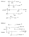
- Figure 1 shows the arrangement of the coupling ports for individual collimators for each port as well as the beam association via the beam splitters ST and the mirrors M.
Landscapes
- Physics & Mathematics (AREA)
- Chemical & Material Sciences (AREA)
- Analytical Chemistry (AREA)
- General Physics & Mathematics (AREA)
- Optics & Photonics (AREA)
- Microscoopes, Condenser (AREA)
- Investigating, Analyzing Materials By Fluorescence Or Luminescence (AREA)
Abstract
zur Darstellung von cellulären Calcium und den zugehörigen Rezeptoren in lebendem Gewebe über lange Zeiträume (time lapse) mit Infrarot- und UV-Lasern, wobei Fluoreszenzdetektion und Uncaging zur Anwendung kommen,
zur Freisetzung von Pharmaka (Uncaging) und IR-Beleuchtung mit Transmissionsdetektion,
zur Realisierung von Applikationen mit fluoreszierenden Proteinen der (G)FP-Familie incl. Photoaktivierung von GFP und CFP/YFP-FRET,
zur Verwendung von CY 5.5-Farbstoffen im dunklroten Bereich (Laser 675nm) für die Tumorforschung.
Description
Die Beobachtung kann dabei mit Transmissionsdetektion wie auch mit Auflicht-Fluoreszenzdetektion am Laser-Scanning-Mikroskop erfolgen.
In DE 19702753 A1 ist ein LSM Strahlengang mit zwei Eingangsports ausführlich beschrieben.
Allerdings ist es vorteilhaft, mehr als drei Koppelports anzuordnen, weil hierdurch der Einsatz jeweils gut chromatisch korrigierter Optik ermöglicht wird.
Die Strahlvereinigung auf einen gemeinsamen Strahl erfolgt aus Gründen der Langzeitstabilität über fest eingebaute, nicht justierbare dichroitische Schichten. Die Strahlvereiniger sitzen im parallelen bzw. je nach z-Position der Kollimationsoptiken im leicht konvergenten oder divergenten Strahlengang. Die Spektral bereiche sind dabei so anzuordnen, das die dichroitischen Schichten vorzugsweise als Lang-, bzw. Kurzpässe ausgeführt werden können und auf diese Weise sowohl die Herstellung zu vereinfachen, als auch aufgrund des weniger komplexen Schichtaufbaus gegenüber einfach, - oder Mehrfachbandpässen die Empfindlichkeit der spektralen Eigenschaften auf Veränderung der Umweltbedingungen minimal zu halten.
Ebenfalls denkbar ist es bei Weiterentwicklungen auf dem Gebiet der Fasertechnik einzelne Faserkoppelports wie z.B. K2 und K3, oder K1 und K3, oder K2und K5, oder K 2, K 3und K 5 zusammenzufassen. Dies hat den Vorteil einer kompakteren Bauweise und eines geringeren mechanischen Aufwandes bei allerdings eingeschränkter Funktionalität. Die Strahlvereiniger ST sitzen in diesem Fall im streng divergenten Strahlengang zwischen Faserendflächen und verfahrbaren Kollimationsoptiken KO 1 bzw. KO 2.
Abbildung 2 zeigt die Anordnung für 5 FaserKoppelports schematisch.
Claims (8)
- Laser-Scanning-Mikroskop mit mindestens vier separaten Einkoppelstellen für Wellenlängenbereiche im UV, im sichtbaren Bereich und im IR Bereich.
- Laser-Scanning-Mikroskop, mit mindestens 4 Einkoppelstellen zu Beleuchtungszwecken mit Laserlicht,
sowie mindestens zwei individuell verschiebbaren Kollimatoren zur Erzielung einer maximalen Flexibilität bei der Auswahl an Farbstoffen und Auswertemethoden - Laser-Scanning-Mikroskop zur Darstellung von zellulären Calcium und den zugehörigen Rezeptoren in lebendem Gewebe über lange Zeiträume (time lapse)mit Infrarot- und UV-Lasern, wobei Fluoreszenzdetektion und Uncaging zur Anwendung kommen, bestehend aus mindestens vier separaten Einkoppelstellen für UV, V, VIS, FR, IR Strahlung.
- Laser-Scanning-Mikroskop mit UV-Lasern zur Freisetzung von Pharmaka (Uncaging) und IR-Beleuchtung mit Transmissionsdetektion, bestehend aus mindestens vier separaten Einkoppelstellen für UV, V, VIS, FR, IR Strahlung Laser-Scanning-Mikroskop zur Realisierung von Applikationen mit fluoreszierenden Proteinen der (G) FP-Familie incl. Photoaktivierung von GFP und CFP/YFP-FRET, bestehend aus mindestens vier separaten Einkoppelstellen für UV, V, VIS, FR, IR Strahlung.
- Laser-Scanning-Mikroskop zur Verwendung von CY 5.5-Farbstoffen im dunkelroten Bereich (Laser 675 nm) für die Tumorforschung, bestehend aus mindestens vier separaten Einkoppelstellen für UV, V, VIS, FR, IR Strahlung
- Laser-Scanning-Mikroskop nach einem der vorangehenden Ansprüche, mit mindestens vier Einkoppelstellen für die Wellenlängenbereiche :350 nm - 380 nm (UV)400 nm - 445 nm (V)450 nm - 635 nm (VIS)650 nm - 680 nm (FR)690 nm - 1100 nm (IR)
- Laser-Scanning-Mikroskop nach einem der vorangehenden Ansprüche, wobei die Einkopplung über mindestens eine Lichtleitfaser erfolgt
- Laser-Scanning-Mikroskop nach einem der vorangehenden Ansprüche, wobei eine wellenlängige Anpassung der Fokuslage über verschiebliche Kollimationsoptiken erfolgt.
Applications Claiming Priority (2)
| Application Number | Priority Date | Filing Date | Title |
|---|---|---|---|
| DE10332063A DE10332063A1 (de) | 2003-07-11 | 2003-07-11 | Laser-Scanning-Mikroskop |
| DE10332063 | 2003-07-11 |
Publications (2)
| Publication Number | Publication Date |
|---|---|
| EP1500962A2 true EP1500962A2 (de) | 2005-01-26 |
| EP1500962A3 EP1500962A3 (de) | 2005-02-09 |
Family
ID=33482972
Family Applications (1)
| Application Number | Title | Priority Date | Filing Date |
|---|---|---|---|
| EP04015825A Ceased EP1500962A3 (de) | 2003-07-11 | 2004-07-06 | Laser-Scanning-Mikroskop mit mindestens vier Einkoppelstellen zu Beleuchtungszwecken |
Country Status (4)
| Country | Link |
|---|---|
| US (1) | US20050072913A1 (de) |
| EP (1) | EP1500962A3 (de) |
| JP (1) | JP2005099724A (de) |
| DE (1) | DE10332063A1 (de) |
Cited By (1)
| Publication number | Priority date | Publication date | Assignee | Title |
|---|---|---|---|---|
| CN108875718A (zh) * | 2018-09-25 | 2018-11-23 | 中国科学院苏州纳米技术与纳米仿生研究所 | 人脸识别系统及其扫描装置 |
Families Citing this family (5)
| Publication number | Priority date | Publication date | Assignee | Title |
|---|---|---|---|---|
| JP2012503798A (ja) | 2008-09-25 | 2012-02-09 | ザ トラスティーズ オブ コロンビア ユニヴァーシティ イン ザ シティ オブ ニューヨーク | 構造物の光刺激およびイメージングを提供するためのデバイス、装置、および方法 |
| JP6313211B2 (ja) | 2011-10-25 | 2018-04-18 | デイライト ソリューションズ、インコーポレイテッド | 赤外撮像顕微鏡 |
| EP2984514B9 (de) | 2013-04-12 | 2021-04-07 | Daylight Solutions Inc. | Anordnung aus infrarotbrechenden objektivlinsen |
| JP2015094887A (ja) * | 2013-11-13 | 2015-05-18 | シチズンホールディングス株式会社 | 共焦点顕微鏡 |
| EP3538941B1 (de) | 2016-11-10 | 2025-04-23 | The Trustees of Columbia University in the City of New York | Schnelles hochauflösendes bildgebungsverfahren für grosse proben |
Family Cites Families (4)
| Publication number | Priority date | Publication date | Assignee | Title |
|---|---|---|---|---|
| DE19758744C2 (de) * | 1997-01-27 | 2003-08-07 | Zeiss Carl Jena Gmbh | Laser-Scanning-Mikroskop |
| DE19951482C2 (de) * | 1999-10-26 | 2003-01-09 | Zeiss Carl Jena Gmbh | Fluoreszenzmikroskop |
| DE10137964B4 (de) * | 2001-08-08 | 2004-04-08 | Leica Microsystems Wetzlar Gmbh | Mikroskop mit umschaltbarer Beleuchtung in mindestens zwei Spektralbereichen und Vorrichtung zur Beleuchtungsumschaltung |
| JP2004029205A (ja) * | 2002-06-24 | 2004-01-29 | Olympus Corp | レーザ走査型顕微鏡 |
-
2003
- 2003-07-11 DE DE10332063A patent/DE10332063A1/de not_active Withdrawn
-
2004
- 2004-07-02 JP JP2004196894A patent/JP2005099724A/ja active Pending
- 2004-07-06 EP EP04015825A patent/EP1500962A3/de not_active Ceased
- 2004-07-09 US US10/888,187 patent/US20050072913A1/en not_active Abandoned
Cited By (1)
| Publication number | Priority date | Publication date | Assignee | Title |
|---|---|---|---|---|
| CN108875718A (zh) * | 2018-09-25 | 2018-11-23 | 中国科学院苏州纳米技术与纳米仿生研究所 | 人脸识别系统及其扫描装置 |
Also Published As
| Publication number | Publication date |
|---|---|
| US20050072913A1 (en) | 2005-04-07 |
| JP2005099724A (ja) | 2005-04-14 |
| DE10332063A1 (de) | 2005-01-27 |
| EP1500962A3 (de) | 2005-02-09 |
Similar Documents
| Publication | Publication Date | Title |
|---|---|---|
| EP1617253B1 (de) | Lichtrastermikroskop mit linienförmiger Abtastung und Verwendung | |
| DE20122782U1 (de) | Beleuchtungseinrichtung | |
| JP2006031004A (ja) | 光走査型顕微鏡およびその使用 | |
| DE112004000340T5 (de) | Mikroskopsystem | |
| DE102012203736A1 (de) | Lichtrastermikroskop mit spektraler Detektion | |
| DE102009043745A1 (de) | Spektraldetektor mit variabler Filterung durch räumliche Farbtrennung und Laser-Scanning- Mikroskop | |
| DE102011106916A1 (de) | Konfokales Auflicht-Rastermikroskop | |
| EP1882969A1 (de) | Laser-Scanning-Mikroskop | |
| EP2045641A2 (de) | Beleuchtungseinrichtung | |
| DE102010060747B4 (de) | Konfokales Laser-Scanmikroskop zum Untersuchen einer Probe | |
| EP1591825B2 (de) | Vorrichtung zur Einkopplung von Licht in einen Strahlengang eines Mikroskops | |
| EP1617268A2 (de) | Lichtrastermikroskop mit einem Beleuchtungsmodul | |
| EP1668394A1 (de) | Mikroskop mit evaneszenter beleuchtung | |
| EP1882970A1 (de) | Laser-Scanning-Mikroskop zur Fluoreszenzuntersuchung | |
| EP1617252B1 (de) | Lichtrastermikroskop mit punktförmiger Lichtquellenverteilung und Verwendung | |
| DE112010004624B4 (de) | Optische Vorrichtung mit einem Phasenfilter und Rastermikroskop mit einem Phasenfilter | |
| DE102014110575A1 (de) | Mikroskop und Verfahren zum optischen Untersuchen und/oder Manipulieren einer mikroskopischen Probe | |
| DE10332063A1 (de) | Laser-Scanning-Mikroskop | |
| DE102005020543A1 (de) | Verfahren und Vorrichtung zur einstellbaren Veränderung von Licht | |
| EP1691229A1 (de) | Operationsmikroskop mit zwei Beleuchtungsvorrichtungen | |
| DE102004034998A1 (de) | Lichtrastermikroskop mit bewegter Lochscheibe und Verwendung | |
| DE19829953B4 (de) | Laser-Scanning-Mikroskop | |
| DE202018103032U1 (de) | Mikroskopiersystem zur Aufnahme eines Konfokalbildes und eines nicht-konfokalen Transmissionsbildes | |
| DE102005042890A1 (de) | Konfokalmikroskop und Verfahren zur Detektion mit einem Konfokalmikroskop | |
| WO2008043459A2 (de) | Anordnung zur aufteilung von detektionslicht |
Legal Events
| Date | Code | Title | Description |
|---|---|---|---|
| PUAI | Public reference made under article 153(3) epc to a published international application that has entered the european phase |
Free format text: ORIGINAL CODE: 0009012 |
|
| PUAL | Search report despatched |
Free format text: ORIGINAL CODE: 0009013 |
|
| 17P | Request for examination filed |
Effective date: 20040706 |
|
| AK | Designated contracting states |
Kind code of ref document: A2 Designated state(s): AT BE BG CH CY CZ DE DK EE ES FI FR GB GR HU IE IT LI LU MC NL PL PT RO SE SI SK TR |
|
| AX | Request for extension of the european patent |
Extension state: AL HR LT LV MK |
|
| AK | Designated contracting states |
Kind code of ref document: A3 Designated state(s): AT BE BG CH CY CZ DE DK EE ES FI FR GB GR HU IE IT LI LU MC NL PL PT RO SE SI SK TR |
|
| AX | Request for extension of the european patent |
Extension state: AL HR LT LV MK |
|
| 17Q | First examination report despatched |
Effective date: 20050608 |
|
| AKX | Designation fees paid |
Designated state(s): AT BE BG CH CY CZ DE DK EE ES FI FR GB GR HU IE IT LI LU MC NL PL PT RO SE SI SK TR |
|
| 17Q | First examination report despatched |
Effective date: 20050608 |
|
| STAA | Information on the status of an ep patent application or granted ep patent |
Free format text: STATUS: THE APPLICATION HAS BEEN REFUSED |
|
| 18R | Application refused |
Effective date: 20071214 |