EP1500583B1 - Anker mit an der Oberseite schräg nach unten gerichtete Seitenflächen aufweisendem Ankerschar - Google Patents
Anker mit an der Oberseite schräg nach unten gerichtete Seitenflächen aufweisendem Ankerschar Download PDFInfo
- Publication number
- EP1500583B1 EP1500583B1 EP04077993A EP04077993A EP1500583B1 EP 1500583 B1 EP1500583 B1 EP 1500583B1 EP 04077993 A EP04077993 A EP 04077993A EP 04077993 A EP04077993 A EP 04077993A EP 1500583 B1 EP1500583 B1 EP 1500583B1
- Authority
- EP
- European Patent Office
- Prior art keywords
- fluke
- anchor
- shank
- plane
- longitudinal
- Prior art date
- Legal status (The legal status is an assumption and is not a legal conclusion. Google has not performed a legal analysis and makes no representation as to the accuracy of the status listed.)
- Expired - Lifetime
Links
- 241000935974 Paralichthys dentatus Species 0.000 title claims abstract description 98
- 230000035515 penetration Effects 0.000 claims abstract description 17
- 230000004308 accommodation Effects 0.000 claims description 6
- 230000005484 gravity Effects 0.000 claims description 6
- 239000003381 stabilizer Substances 0.000 claims description 4
- 229910000831 Steel Inorganic materials 0.000 claims description 2
- 239000010959 steel Substances 0.000 claims description 2
- 239000002689 soil Substances 0.000 description 7
- 238000004873 anchoring Methods 0.000 description 5
- 230000001154 acute effect Effects 0.000 description 2
- 238000010276 construction Methods 0.000 description 1
- 238000000034 method Methods 0.000 description 1
- 230000000149 penetrating effect Effects 0.000 description 1
- 238000007665 sagging Methods 0.000 description 1
- 239000004576 sand Substances 0.000 description 1
- 239000007787 solid Substances 0.000 description 1
- XLYOFNOQVPJJNP-UHFFFAOYSA-N water Substances O XLYOFNOQVPJJNP-UHFFFAOYSA-N 0.000 description 1
Images


Classifications
-
- B—PERFORMING OPERATIONS; TRANSPORTING
- B63—SHIPS OR OTHER WATERBORNE VESSELS; RELATED EQUIPMENT
- B63B—SHIPS OR OTHER WATERBORNE VESSELS; EQUIPMENT FOR SHIPPING
- B63B21/00—Tying-up; Shifting, towing, or pushing equipment; Anchoring
- B63B21/24—Anchors
- B63B21/26—Anchors securing to bed
-
- B—PERFORMING OPERATIONS; TRANSPORTING
- B63—SHIPS OR OTHER WATERBORNE VESSELS; RELATED EQUIPMENT
- B63B—SHIPS OR OTHER WATERBORNE VESSELS; EQUIPMENT FOR SHIPPING
- B63B21/00—Tying-up; Shifting, towing, or pushing equipment; Anchoring
- B63B21/24—Anchors
- B63B21/30—Anchors rigid when in use
- B63B21/34—Anchors rigid when in use with two or more flukes
-
- B—PERFORMING OPERATIONS; TRANSPORTING
- B63—SHIPS OR OTHER WATERBORNE VESSELS; RELATED EQUIPMENT
- B63B—SHIPS OR OTHER WATERBORNE VESSELS; EQUIPMENT FOR SHIPPING
- B63B21/00—Tying-up; Shifting, towing, or pushing equipment; Anchoring
- B63B21/24—Anchors
- B63B21/30—Anchors rigid when in use
- B63B21/32—Anchors rigid when in use with one fluke
-
- B—PERFORMING OPERATIONS; TRANSPORTING
- B63—SHIPS OR OTHER WATERBORNE VESSELS; RELATED EQUIPMENT
- B63B—SHIPS OR OTHER WATERBORNE VESSELS; EQUIPMENT FOR SHIPPING
- B63B21/00—Tying-up; Shifting, towing, or pushing equipment; Anchoring
- B63B21/24—Anchors
- B63B21/26—Anchors securing to bed
- B63B2021/262—Anchors securing to bed by drag embedment
Definitions
- the invention relates to an anchor comprising a fluke and a shank according to the preamble of claim 1.
- Such an anchor is known from WO 97/00196 A .
- the invention provides an anchor comprising a fluke and a shank as claimed in claim 1.
- an anchor comprising a fluke and a shank as claimed in claim 1.
- the passage of soil by the shank is improved whereas the space underneath the fluke is shielded to the side, as a result of which parts situated there, such as in case of an adjustable shank its adjustment lip, get damaged less quickly.
- the planes of the fluke running obliquely to the side moreover improve the passage of the anchor over the roll of a supply vessel. Furthermore the stability during penetration is improved.
- the fluke forms a hollow body (box) having a lower surface which in the area underneath the said planar plane of the upper surface comprises two planes that incline sideward and downward and meet each other according to a top line that is situated in a longitudinal plane of symmetry of the anchor.
- the cross-section in transverse direction of the fluke corresponds to the line of moments, in which a small height is present in the middle, where -considered in cross-section- the smallest moments as a result of the soil pressure are present, but a larger height at the location of the attachment of the shank legs. Nonetheless the passage of the soil over the shank, between the shank legs, is impeded as little as possible because at that location the upper surface is as straight and therefore as small as possible.
- the lower surface of the fluke is continued to the side, up to the side edges in planes running obliquely downward, as a result of which the directional stability is further improved, and also the -hollow- fluke construction can remain simple.
- the fluke preferably has an inverted V-shape.
- the invention provides an anchor comprising a fluke and a shank extending upwards and forward from the fluke, which shank at a first end is attached to the fluke and at a second end that is situated opposite to the first end, is provided with means for attachment of the anchor to a penetration line or anchor line, in which the shank is rigid and the fluke at the lower side is provided with lower surfaces for supporting the lower side of the fluke according to a first support surface, in which the shank extends to the second end substantially parallel to the first support surface.
- This is advantageous for the initial penetrating of the fluke in the anchoring soil, but also advantageous when storing the anchor on board of a supply vessel and when preparing the anchor, in particular the second end of the shank, at that location.
- the shank comprises two cranked shank legs that converge to the second end.
- the fluke has an upper surface, which at the front considered in a vertical longitudinal sectional plane is at an angle of approximately 10-30°, preferably 20-30°, preferably approximately 25°, to the first support surface. As a result the penetration characteristics of the fluke are improved.
- the invention provides an anchor comprising a fluke and a rigid shank during use extending upwards and forward from the fluke, which shank at a first end is attached to the fluke and at a second end that is situated opposite to the first end, is provided with means for attachment of the anchor to a penetration line or anchor line, in which the fluke forms a hollow body of plates and has an upper surface and a lower surface, which from front to rear diverge with respect to each other, considered in a longitudinal sectional plane, to a rear side of the fluke, in which the anchor has a reference line running through the centre of gravity of the anchor and through the point of force application of the penetration line on the second end of the shank, in which the rear side of the fluke at the lower side is provided with transverse edges, that are situated rearward from the reference line.
- the anchor comes down, pending with the reference line vertically, it will first come down on the transverse edges. Because of the rearward position of the transverse edges, the anchor will be inclined to tilt forward from an initially in
- the transverse edges are situated on both sides of the longitudinal plane of symmetry of the anchor and are in line with each other, so that a kind of rotation or tilting edge is obtained at the rear side of the fluke.
- the transverse edges form the rear boundary of second support surfaces that are part of the lower surface of the fluke, of which surfaces the opposite of the normal is at an angle to the reference line, which angle opens in rearward direction of the anchor.
- the rear side of the fluke forms second support surfaces, of which the opposite of the normal is at an acute angle to the reference line, which opens in rearward direction of the anchor.
- the second support surfaces are situated on both sides of the longitudinal plane of symmetry of the anchor, particularly at a distance from the longitudinal plane of symmetry, preferably contiguous to the side edges of the fluke, as a result of which the fluke when coming down on the anchoring bottom -considered in transverse direction- can first take up a stable position before tilting forward.
- the distance between the second support surfaces moreover offers more possibilities for realising soil flow improving provisions on the fluke, such as for instance the V-shaped tunnel at the lower side of the fluke mentioned earlier.
- the fluke forms a hollow body of plates and has an upper surface and a lower surface, which from front to rear diverge with respect to each other, considered in a longitudinal sectional plane, to a rear side of the fluke, in which the rear side of the fluke forms planes, which are oriented obliquely rearward and upward when the fluke is placed on a level base. In this way the soil flow over the rear side of the fluke is improved.
- the fluke forms a hollow body of plates and has an upper surface and a lower surface, which from front to rear diverge with respect to each other, considered in a longitudinal sectional plane, to a rear side of the fluke, in which the shank is rigid and comprises two shank legs that are attached at the first end to two longitudinal girders in the fluke, which longitudinal girders each comprise two parallel strip-shaped plates, which between them define an accommodation space for an attachment lip at the first end of the shank legs, in which the strip-shaped plates extend from the front edge of the fluke to the rear edge.
- Said longitudinal girders are a part of the structure of the fluke. Because of its continuous double design the solidity is increased, and more mounting possibilities are also provided, such as for penetration points and for the front parts of the first end of the shank legs.
- the strip-shaped plates are connected to each other by means of a steel transverse strip.
- both longitudinal strips are counteracted to deform towards each other.
- a kind of box girder can be formed as a result of which the strength is improved.
- the front ends of the box girders moreover form a suitable accommodation space for the penetration points.
- the invention provides an anchor, in which the fluke forms a hollow body of plates and has an upper surface and a lower surface, which from front to rear diverge with respect to each other, considered in a longitudinal sectional plane, to a rear side of the fluke, in which in the outermost laterally situated areas of the fluke side planes have been formed having a normal that is substantially perpendicular to a longitudinal plane of symmetry of the anchor.
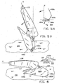
- the shank legs 106a, 106b diverge in downward direction with respect to each other, up to buckle-lines T1 and T2, where they are continued in downward direction in parallel and vertical plates 170a, 170b.
- plates 172a, 172b have also been provided at the front, through which attachment pins 108a, 108b may extend for securing the shank 106 to the fluke 102.
- lips 171 a, 171 b provided with several holes have been provided, so that with the help of pins 109a, 109b the shank can be attached to the fluke at various angled positions.
- the position is shown in which the angle between the shank and the fluke is the largest.
- the upper surface 105 of the fluke 102 has a planar plane 161, which extends rearward from the front edge 103, between the shank legs, and ends in a transverse line, in order to merge into a kind of gate or mirror surfaces 162a, 1 62b, that are in one plane with each other.
- the normal N1 to the mirror surfaces 162a, 162b is upwardly inclined oriented to the rear with respect to the fluke 102.
- the lower boundary of the mirror surfaces 162a, 162b is somewhat V-shaped, in order to be contiguous to tunnel Y, to be further discussed, at the lower surface of the fluke 102. Outside of it the lower boundaries of the mirror surfaces 162a, 162b are parallel to the upper boundary and therefore transverse to the plane of symmetry S of the anchor 101.
- first side planes 160a, 160b that run downwardly inclined to the side edge of the fluke, at an angle ⁇ of 10-40°, preferably 30°.
- the side edges are parallel to each other and to the plane of symmetry S, and they form planar second side planes 190a, 190b, that are also parallel to the plane of symmetry S.
- the lower surface of the fluke 102 is built up from several plates, and, as can be seen in figure 2C , has a substantially inverted V-shape to form a kind of tunnel Y.
- Said tunnel is advantageous when hauling in the anchor upside-down over the roll of a supply vessel, because the anchor line that is still connected to the anchor and the object to be anchored, such as an oil rig, is centred somewhat then, so that the force as a result of the anchor line (many hundreds of metres long) sagging in the water can be exerted onto the anchor in a centred manner.
- first planes 183a, 183b are provided below the planar plane 161 of the upper fluke surfaces 105, which plates come together with the planar plane 161 at the front edge, and at the rear edge merge in the inclined lower edges of the mirror surfaces 162a, 162b.
- a plate 184 Adjacent to it are longitudinal girders 150a, 150b to be further discussed, at the outside of which the lower surface 180 of the fluke 102 is continued outward in second planes 185a, 185b that are inclined as well, of which the angle ⁇ , as can be seen in figure 2C , is equal to that of the first planes 183a and 183b and which may be 5-30°.
- the second planes 185a, 185b merge into an edge with the first side planes 160a, 160b of the upper surfaces of the fluke 102.
- the second planes 185a, 185b merge into second support surfaces 181 a, 181 b, that are situated in one plane with each other and of which the opposite of the normal N2 is at a rearward opening acute angle ⁇ , considered in the plane of symmetry S, with respect to the line Q (figure 10) through the centre of gravity of the anchor and the point of engagement (pin 115) of the anchor line at the upper end of the shank, during lowering the anchor.
- the second support surfaces 181a, b end at the rear in transverse edges 188a, b, that also form the rear boundary of the mirror surfaces 162a, b and are in line with each other, perpendicular to the longitudinal plane of symmetry S. This is further gone into in the discussion of the figures 5A,B and 6 .
- the second planes 185a, b connect to stabiliser planes 182a, 182b which with their normals N3 are oriented towards each other, forward and downward.
- the longitudinal girders 150a, 150b are each built up from two longitudinal plates 151 a, 152a and 151 b, 152b, respectively. Between them they determine slit-shaped passages 153a, 153b, that are parallel to each other and to the plane of symmetry S. They accommodate hinge plates 172a, 172b and lips 171 a, 171 b in between them and form accommodation space 155 (see figures 3 and 4 ), in which a penetration tooth 156 can attachedly be accommodated.
- the longitudinal plates are provided with a front lower edge portion 154a, b and a rear lower edge portion 157a, 157b, respectively, that is at an angle with respect to the front lower edge portion and runs more or less parallel to the planar plane 161 of the fluke 102.
- both front lower edge portions 154a, 154b are connected to each other by means of strips 158a, b, which also downwardly limit the accommodation spaces 155.
- the angles between the first side planes 160a, 1 60b and planar plane 161 on the one hand and the first and second planes 183a, b and 185a, b on the other hand, measured from the front edge 103 in a cross-sectional plane parallel to the plane of symmetry S, is always constant.
- Said angle can be determined depending on the soil type, and preferably is between 0° and 20°, preferably 10°.
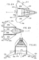
- FIG 5A The moment of coming down of the anchor 101 on an anchoring bottom 200 is shown in figure 5A , in this example planar and horizontal.
- the line Q (see figure 5B ) is vertical because of the pin 115 and the centre of gravity Z, and the second support surfaces 181 a, 181 b with their normals N2 are oriented downward to the right, as seen in the drawing.
- the reference line Q is at an forwardly opening angle ⁇ to the opposite of the normal N2.
- the edges 188a, b that are forming a vertex line between the mirror surfaces 162a, b and the second support surfaces 181a, b are situated at the right -as seen in the drawing-, that is to say behind the line Q and therefore the centre of gravity Z, in which the penetration side or front side of the fluke is situated at the left.
- the anchor 101 When coming down the anchor 101 will first come to support on the edges 188a, 188b, in which due to the forward position of the centre of gravity the anchor 101 will tilt forward.
- the second support surfaces 181 a, 181b prevent an all to deep penetration into the bottom, as a result of which the tilting might otherwise be impeded.
- the line Q is already tilted somewhat to the left and will tilt further to the position shown in figure 6 .
- the anchor 101 is shown, in which the shank is adjusted at an angle for penetration in sand, with the smallest possible shank angle (the largest angle is for mud).
- the shank 106 here extends in the direction H, parallel to the ground surface 200. In this position the anchor rests on the front tips as well as on the lower edges of the side planes 190a, b.
- the upper end of the shank legs is at a distance of the basis. This situation can also be realised on deck, which facilitates mounting actions at the shank end.
- From the front edge 103 the first side planes 160a, 160b is at an angle ⁇ , seen in the cross-sectional plane parallel to the plane of symmetry S, of 25° to the floor area.
- the second planes 185a,b are at an angle ⁇ of 10° to the upper surface.
Landscapes
- Engineering & Computer Science (AREA)
- Combustion & Propulsion (AREA)
- Mechanical Engineering (AREA)
- Ocean & Marine Engineering (AREA)
- Chemical & Material Sciences (AREA)
- Piles And Underground Anchors (AREA)
- Joining Of Building Structures In Genera (AREA)
- Slide Fasteners, Snap Fasteners, And Hook Fasteners (AREA)
- Stringed Musical Instruments (AREA)
- Dowels (AREA)
- Supports Or Holders For Household Use (AREA)
- Orthopedics, Nursing, And Contraception (AREA)
- Cephalosporin Compounds (AREA)
- Golf Clubs (AREA)
- Devices Affording Protection Of Roads Or Walls For Sound Insulation (AREA)
- Crystals, And After-Treatments Of Crystals (AREA)
Claims (15)
- Anker (101), umfassend eine Flunke (102) und einen sich von der Flunke (102) nach oben und vorn erstreckenden Schaft (106), wobei Schaft (106) an einem ersten Ende (107) an der Flunke (102) befestigt ist und an einem zweiten Ende (112), das sich gegenüber dem ersten Ende (107) befindet, mit Mitteln (114) zur Befestigung des Ankers (101) an einer Verankerungs- oder Ankerleine versehen ist, wobei der Schaft (106) starr ist und zwei Schaftbeine (106a, 106b) umfasst, wobei die Flunke (102) eine Oberseite (105) aufweist, die am Ort des ersten Endes (107) des Schafts (106) eine im Wesentlichen ebene Fläche (161) bildet, die senkrecht auf einer Längssymmetrieebene (S) des Ankers (101) steht und vorzugsweise von der Vorderkante (103) bis zur Hinterkante (104) durchgängig ist, wobei die Oberseite (105) der Flunke außerhalb der Schaftbeine (106a, 106b) erste Seitenebenen (160a, 160b) bildet, die schräg zur Seite und nach unten verlaufen, dadurch gekennzeichnet, dass die Flunke (102) einen Hohlkörper aus Platten bildet und eine Oberseite (105) und eine Unterseite (180) aufweist, die, in einer Längsschnittebene betrachtet, von vorn nach hinten, zu einer Rückseite der Flunke (102), auseinanderstreben, wobei in den äußersten seitlichen Bereichen der Flunke (102) zweite Seitenebenen (190a, 190b) ausgebildet sind, deren Normale im Wesentlichen senkrecht auf einer Längssymmetrieebene (S) des Ankers steht.
- Anker nach Anspruch 1, wobei sich die ebene Fläche (161) vom ersten Ende (107a) eines der Schaftbeine (106a) bis zum ersten Ende (107b) des anderen der Schaftbeine (106b) erstreckt.
- Anker nach Anspruch 1 oder 2, wobei der Anker (101) kastenförmig ist.
- Anker nach Anspruch 3, wobei die Flunke (102) eine Unterseite (180) aufweist, die in dem Bereich unterhalb der zuvor erwähnten ebenen Fläche (161) der Oberseite (105) zwei erste Flächen (183a, 183b) umfasst, die seitwärts und nach unten geneigt sind und gemäß einer oberen Linie, die in einer Längssymmetrieebene (S) des Ankers (101) liegt, aufeinandertreffen.
- Anker nach Anspruch 4, wobei die Unterseite (180) der Flunke (102) zur Seite bis zu den Seitenkanten in zweiten Ebenen (185a, 185b), die schräg nach unten verlaufen, weitergeführt ist.
- Anker nach einem der Ansprüche 1 bis 5, wobei die Flunke (102), in einer Schnittebene (II C), senkrecht zur Längssymmetrieebene (S) betrachtet, eine umgekehrte V-Form aufweist.
- Anker nach Anspruch 1, wobei angrenzend an die zweiten Seitenebenen (190a, 190b) Stabilisatorflächen (182a, 182b), die schräg nach innen und unten ausgerichtet sind, an der Unterseite (180) der Flunke (102) ausgebildet worden sind.
- Anker nach einem der vorhergehenden Ansprüche, wobei die Flunke (102) an der Unterseite (180) mit unteren Flächen zum Stützen der Unterseite der Flunke entsprechend einer ersten Auflagefläche versehen ist, wobei der Schaft (106) so ausgerichtet sein kann, dass er sich zu dem zweiten Ende (112) im Wesentlichen parallel zur ersten Auflagefläche erstreckt, wobei vorzugsweise der Schaft (106) zwei gekröpfte Schaftbeine (106a, 106b) umfasst, die zum zweiten Ende (112) zusammenstreben.
- Anker nach Anspruch 8, wobei die Flunke (102) eine Oberseite (105) aufweist, die vorn, in einer vertikalen Längsschnittebene (S) betrachtet, in einem Winkel von ungefähr 10-30°, vorzugsweise 20-30°, vorzugsweise ungefähr 25°, zu der ersten Auflagefläche vorliegt.
- Anker nach einem der vorhergehenden Ansprüche, wobei die Flunke (102) einen Hohlkörper aus Platten darstellt und eine Oberseite (105) und eine Unterseite (180) aufweist, die, in einer Längsschnittebene (S) betrachtet, von vorn nach hinten, zu einer Rückseite der Flunke (102), auseinanderstreben, wobei der Anker (101) eine Bezugslinie (Q) aufweist, die durch den Schwerpunkt (Z) des Ankers (101) und durch den Punkt des Kraftangriffs (115) der Verankerungsleine am zweiten Ende (112) des Schafts (106) verläuft, wobei die Rückseite der Flunke (102) an der Unterseite mit Querkanten (188a, 188b) versehen ist, die sich hinter der Bezugslinie (Q) befinden.
- Anker nach Anspruch 10, wobei sich die Querkanten (188a, 188b) an beiden Seiten der Längssymmetrieebene (S) des Ankers (101) befinden und fluchtend zueinander sind.
- Anker nach Anspruch 10 oder 11, wobei die Querkanten (188a, 188b) die hintere Begrenzung zweiter Auflageflächen (181a, 181b) bilden, die Teil der Unterseite (180) der Flunke (102) sind, wobei die Entgegengesetzte zu der Normalen (N2) der zweiten Flächen (181 a, 181 b) in einem Winkel zur Bezugslinie (Q) vorliegt, der entgegen der Bewegungsrichtung des Ankers (101) offen ist, wobei vorzugsweise sich die zweiten Auflageflächen (181a, 181b) an beiden Seiten der Längssymmetrieebene (S) des Ankers (101), vorzugsweise in einem Abstand von der Längssymmetrieebene (S), vorzugsweise an die Seitenkanten der Flunke (102) angrenzend befinden.
- Anker nach einem der vorhergehenden Ansprüche, wobei die Flunke (102) einen Hohlkörper aus Platten darstellt und eine Oberseite (105) und eine Unterseite (180) aufweist, die, in einer Längsschnittebene (S) betrachtet, von vorn nach hinten, zu einer Rückseite der Flunke (102), auseinanderstreben, wobei die Rückseite der Flunke (102) zweite Auflageflächen (181a, 181b) bildet, die schräg nach hinten und oben ausgerichtet sind, wenn die Flunke auf Grund liegt.
- Anker nach einem der vorhergehenden Ansprüche, wobei die Flunke (102) einen Hohlkörper aus Platten darstellt und eine Oberseite (105) und eine Unterseite (180) aufweist, die, in einer Längsschnittebene (S) betrachtet, von vorn nach hinten, zu einer Rückseite der Flunke, auseinanderstreben, wobei der Schaft (106) starr ist und zwei Schaftbeine (106a, 106b) umfasst, die am ersten Ende (107a, 107b) an zwei Längsträgern (150a, 150b) in der Flunke (102) befestigt sind, wobei die Längsträger (150a, 150b) jeweils zwei parallele streifenförmige Platten (151a, 152a und 151b, 152b) umfassen, die zwischen sich einen Aufnahmeraum (155) für eine Befestigungslippe (171a, 171b) am ersten Ende (107a, 107b) der Schaftbeine (106a, 106b) bestimmen, wobei sich die streifenförmigen Platten (151a, 152a und 151b, 152b) von der Vorderkante (103) der Flunke zur Hinterkante (104) erstrecken.
- Anker nach Anspruch 14, wobei an der Vorderkante der Flunke (102) Eindringspitzen (156) in den zwischen beiden streifenförmigen Platten (151a, 152a und 151b, 152b) jedes Längsträgers (150a, 150b) ausgebildeten Aufnahmeräumen (155) angebracht worden sind, wobei vorzugsweise die streifenförmigen Platten (151a, 152a und 151b, 152b) mindestens in einem vorderen Abschnitt mittels einer Querleiste (158a, 158b) aus Stahl miteinander verbunden sind.
Priority Applications (1)
| Application Number | Priority Date | Filing Date | Title |
|---|---|---|---|
| CY20111100451T CY1111449T1 (el) | 2000-04-27 | 2011-05-12 | Αγκυρα με αγκιστρο που εχει μια πανω επιφανεια που περιλαμβανει πλευρικα πτερυγια κεκλιμενα προς τα κατω |
Applications Claiming Priority (3)
| Application Number | Priority Date | Filing Date | Title |
|---|---|---|---|
| NL1015034 | 2000-04-27 | ||
| NL1015034 | 2000-04-27 | ||
| EP01926236A EP1276662B1 (de) | 2000-04-27 | 2001-04-27 | Anker mit schaft |
Related Parent Applications (2)
| Application Number | Title | Priority Date | Filing Date |
|---|---|---|---|
| EP01926236.9 Division | 2001-04-27 | ||
| EP01926236A Division EP1276662B1 (de) | 2000-04-27 | 2001-04-27 | Anker mit schaft |
Publications (3)
| Publication Number | Publication Date |
|---|---|
| EP1500583A2 EP1500583A2 (de) | 2005-01-26 |
| EP1500583A3 EP1500583A3 (de) | 2005-02-16 |
| EP1500583B1 true EP1500583B1 (de) | 2011-04-20 |
Family
ID=19771273
Family Applications (2)
| Application Number | Title | Priority Date | Filing Date |
|---|---|---|---|
| EP04077993A Expired - Lifetime EP1500583B1 (de) | 2000-04-27 | 2001-04-27 | Anker mit an der Oberseite schräg nach unten gerichtete Seitenflächen aufweisendem Ankerschar |
| EP01926236A Expired - Lifetime EP1276662B1 (de) | 2000-04-27 | 2001-04-27 | Anker mit schaft |
Family Applications After (1)
| Application Number | Title | Priority Date | Filing Date |
|---|---|---|---|
| EP01926236A Expired - Lifetime EP1276662B1 (de) | 2000-04-27 | 2001-04-27 | Anker mit schaft |
Country Status (15)
| Country | Link |
|---|---|
| US (3) | US6901878B2 (de) |
| EP (2) | EP1500583B1 (de) |
| CN (2) | CN1210181C (de) |
| AT (2) | ATE506246T1 (de) |
| AU (2) | AU2001252768B2 (de) |
| BR (1) | BR0110376B1 (de) |
| CY (1) | CY1111449T1 (de) |
| DE (2) | DE60107069D1 (de) |
| DK (1) | DK1500583T3 (de) |
| ES (2) | ES2365397T3 (de) |
| HK (2) | HK1073092A1 (de) |
| NO (2) | NO328437B1 (de) |
| OA (1) | OA12254A (de) |
| PT (2) | PT1276662E (de) |
| WO (1) | WO2001081161A2 (de) |
Families Citing this family (14)
| Publication number | Priority date | Publication date | Assignee | Title |
|---|---|---|---|---|
| CN1210181C (zh) * | 2000-04-27 | 2005-07-13 | 弗里霍夫锚控股有限责任公司 | 具有锚柄的锚 |
| WO2008000032A1 (en) * | 2006-06-29 | 2008-01-03 | Jeyco(1992) Pty Ltd | Anchor |
| WO2009032799A1 (en) * | 2007-09-05 | 2009-03-12 | Delmar Systems, Inc. | Anchors for mooring of objects in a marine environment |
| GB2461605B (en) | 2009-04-08 | 2010-05-19 | Edmund Fitch | An anchor positioning system |
| CN102050206B (zh) * | 2009-11-09 | 2014-08-20 | 江苏扬远船舶设备铸造有限公司 | 具有齿边结构的大抓力锚锚干 |
| GB201018670D0 (en) * | 2010-11-05 | 2010-12-22 | Brupat Ltd | Anchor data communicaiton system |
| CN102582791B (zh) * | 2012-03-15 | 2016-01-20 | 重庆鑫业船舶件有限公司 | 大抓力锚 |
| GB2522196B (en) | 2014-01-15 | 2016-02-10 | Fe Anchor Corp | Anchor with shank retaining fastener |
| CN105460169A (zh) * | 2015-06-12 | 2016-04-06 | 新兴重工湖北三六一一机械有限公司 | 一种轻量型可调节角度拉力锚 |
| NL2015665B1 (en) * | 2015-10-27 | 2017-05-24 | Stevlos Bv | Anchor. |
| NL2015666B1 (en) * | 2015-10-27 | 2017-05-29 | Stevlos Bv | Anchor with angle adjustment provision. |
| USD792319S1 (en) * | 2015-10-30 | 2017-07-18 | Stevlos B.V. | Anchor |
| CN106697198B (zh) * | 2016-12-16 | 2018-07-27 | 浙江海洋大学东海科学技术学院 | 一种锚泊定位装置 |
| CN108423125B (zh) * | 2018-05-14 | 2023-11-24 | 大连理工大学 | 一种新型轻质动力安装锚及安装方法 |
Family Cites Families (19)
| Publication number | Priority date | Publication date | Assignee | Title |
|---|---|---|---|---|
| DE242975C (de) * | ||||
| US3774569A (en) * | 1971-10-26 | 1973-11-27 | Boldt Corp | Anchor |
| NL7115016A (de) * | 1971-11-01 | 1973-05-03 | ||
| GB1553080A (en) * | 1976-07-19 | 1979-09-19 | Parsons Controls Ltd | Swivel connector |
| FI71701C (fi) * | 1980-09-25 | 1987-02-09 | Den Haak Rob Van | Ankare. |
| DE3037596C2 (de) | 1980-10-04 | 1983-12-15 | Siegfried 7135 Wiernsheim Fricker | Formkörper zur Halterung eines Ankers beim Betonieren eines Betonfertigteiles |
| FR2519310B1 (fr) * | 1982-01-05 | 1987-03-20 | Inst Francais Du Petrole | Dispositif d'ancrage |
| CN86100338A (zh) * | 1986-01-21 | 1987-08-05 | 罗布·万·丹·哈克 | 锚 |
| GB8808373D0 (en) * | 1988-04-09 | 1988-05-11 | Simpson-Lawrence Ltd | Marine anchor |
| NL8802975A (nl) * | 1988-12-02 | 1990-07-02 | Haak Rob Van Den | Anker met kruisverband. |
| NL9001315A (nl) * | 1990-06-11 | 1992-01-02 | Haak Rob Van Den | Jachtankersamenstel. |
| GB9125241D0 (en) * | 1991-11-27 | 1992-01-29 | Brupat Ltd | Drag embedment marine anchor |
| EP0596157B1 (de) * | 1992-11-02 | 1997-05-28 | Single Buoy Moorings Inc. | Schwerlastanker |
| NL9202083A (nl) * | 1992-12-01 | 1994-07-01 | Vrijhof Ankers Beheer Bv | Ankervloei. |
| NL1000583C2 (nl) | 1995-06-16 | 1996-12-17 | Vrijhof Ankers Beheer Bv | Ankervloei. |
| BR9603600A (pt) * | 1996-08-30 | 1998-05-19 | Petroleo Brasileiro Sa | Ancora do tipo placa e seu respectivo processo de instalação |
| US6082284A (en) * | 1996-11-04 | 2000-07-04 | Vrijhof Ankers Beheer B.V. | Anchor |
| US6220198B1 (en) * | 1998-04-30 | 2001-04-24 | Brupat Limited | Marine anchors |
| CN1210181C (zh) * | 2000-04-27 | 2005-07-13 | 弗里霍夫锚控股有限责任公司 | 具有锚柄的锚 |
-
2001
- 2001-04-27 CN CNB018086772A patent/CN1210181C/zh not_active Expired - Lifetime
- 2001-04-27 BR BRPI0110376-8A patent/BR0110376B1/pt not_active IP Right Cessation
- 2001-04-27 ES ES04077993T patent/ES2365397T3/es not_active Expired - Lifetime
- 2001-04-27 AU AU2001252768A patent/AU2001252768B2/en not_active Expired
- 2001-04-27 OA OA1200200327A patent/OA12254A/en unknown
- 2001-04-27 DK DK04077993.6T patent/DK1500583T3/da active
- 2001-04-27 AT AT04077993T patent/ATE506246T1/de not_active IP Right Cessation
- 2001-04-27 AT AT01926236T patent/ATE281969T1/de not_active IP Right Cessation
- 2001-04-27 AU AU5276801A patent/AU5276801A/xx active Pending
- 2001-04-27 CN CNB2005100781187A patent/CN100377966C/zh not_active Expired - Lifetime
- 2001-04-27 EP EP04077993A patent/EP1500583B1/de not_active Expired - Lifetime
- 2001-04-27 DE DE60107069T patent/DE60107069D1/de not_active Expired - Lifetime
- 2001-04-27 PT PT01926236T patent/PT1276662E/pt unknown
- 2001-04-27 DE DE60144495T patent/DE60144495D1/de not_active Expired - Lifetime
- 2001-04-27 ES ES01926236T patent/ES2232616T3/es not_active Expired - Lifetime
- 2001-04-27 PT PT04077993T patent/PT1500583E/pt unknown
- 2001-04-27 EP EP01926236A patent/EP1276662B1/de not_active Expired - Lifetime
- 2001-04-27 WO PCT/NL2001/000325 patent/WO2001081161A2/en active IP Right Grant
-
2002
- 2002-10-16 US US10/272,438 patent/US6901878B2/en not_active Expired - Lifetime
- 2002-10-24 NO NO20025119A patent/NO328437B1/no not_active IP Right Cessation
-
2003
- 2003-06-23 HK HK05105736.3A patent/HK1073092A1/xx unknown
- 2003-06-23 HK HK03104499.5A patent/HK1053813B/zh not_active IP Right Cessation
-
2005
- 2005-05-18 US US11/131,801 patent/US7156041B2/en not_active Expired - Lifetime
-
2006
- 2006-11-14 US US11/599,764 patent/US7467597B2/en not_active Expired - Fee Related
-
2008
- 2008-12-23 NO NO20085381A patent/NO338196B1/no not_active IP Right Cessation
-
2011
- 2011-05-12 CY CY20111100451T patent/CY1111449T1/el unknown
Also Published As
Similar Documents
| Publication | Publication Date | Title |
|---|---|---|
| EP1500583B1 (de) | Anker mit an der Oberseite schräg nach unten gerichtete Seitenflächen aufweisendem Ankerschar | |
| AU2001252768A1 (en) | Anchor comprising a shank | |
| US5353732A (en) | Anchor for heavy loads | |
| EP1060982A2 (de) | Installation von Decks auf Offshore-Substrukturen | |
| NL1014314C2 (nl) | Werkwijze voor het verwijderen of plaatsen van een onderstel van een offshore-platform. | |
| US4731942A (en) | Dozer blade | |
| US7117809B2 (en) | Floating dry dock for light watercrafts | |
| US6811456B2 (en) | Wakeboard and kiteboard with curved fins and methods of use | |
| KR950012272B1 (ko) | 앵커 | |
| JPH0631508B2 (ja) | はしご水平調整装置 | |
| US20060243182A1 (en) | Construction of amahs | |
| AU2005209674B2 (en) | Anchor comprising a shank | |
| EP0180609A1 (de) | Apparat mit ankerschaufeln zum eingraben. | |
| GB2266683A (en) | Ice-beaking ship | |
| SE506794C2 (sv) | Lastbärarstång | |
| NL1015357C1 (nl) | Wandsegment, wand opgebouwd uit dergelijke wandsegmenten en werkwijze voor het vormen van een kade met behulp van de wandsegmenten. | |
| NL1027171C1 (nl) | Bodemscherm. | |
| FR2525937A1 (fr) | Dispositif d'introduction d'un metal liquide dans une lingotiere de coulee continue de brames | |
| KR200427763Y1 (ko) | 보강토 블록 | |
| JP2002327442A (ja) | 双胴式ケーソン回航支援装置 | |
| FR2855196A1 (fr) | Dispositif de nivellement | |
| FR2740103A1 (fr) | Greement mobile permettant d'augmenter sensiblement les performances d'engins a voile | |
| JPH11315523A (ja) | 鋼矢板壁の笠コンクリートの施工方法 | |
| ITCO20010005A1 (it) | Imbarcazioni a vela tipo pluriscafi caratterizzate da sistemi innovativi di controllo dell'assetto di navigazione e di stazionamento. | |
| RU99111051A (ru) | Траншейный трубоподъемник |
Legal Events
| Date | Code | Title | Description |
|---|---|---|---|
| PUAI | Public reference made under article 153(3) epc to a published international application that has entered the european phase |
Free format text: ORIGINAL CODE: 0009012 |
|
| PUAL | Search report despatched |
Free format text: ORIGINAL CODE: 0009013 |
|
| AC | Divisional application: reference to earlier application |
Ref document number: 1276662 Country of ref document: EP Kind code of ref document: P |
|
| AK | Designated contracting states |
Kind code of ref document: A2 Designated state(s): AT BE CH CY DE DK ES FI FR GB GR IE IT LI LU MC NL PT SE TR |
|
| AK | Designated contracting states |
Kind code of ref document: A3 Designated state(s): AT BE CH CY DE DK ES FI FR GB GR IE IT LI LU MC NL PT SE TR |
|
| 17P | Request for examination filed |
Effective date: 20050523 |
|
| REG | Reference to a national code |
Ref country code: HK Ref legal event code: DE Ref document number: 1073092 Country of ref document: HK |
|
| AKX | Designation fees paid |
Designated state(s): AT BE CH CY DE DK ES FI FR GB GR IE IT LI LU MC NL PT SE TR |
|
| 17Q | First examination report despatched |
Effective date: 20070809 |
|
| RAP1 | Party data changed (applicant data changed or rights of an application transferred) |
Owner name: STEVLOS B.V. |
|
| RIC1 | Information provided on ipc code assigned before grant |
Ipc: B63B 21/32 20060101AFI20100916BHEP |
|
| GRAP | Despatch of communication of intention to grant a patent |
Free format text: ORIGINAL CODE: EPIDOSNIGR1 |
|
| GRAS | Grant fee paid |
Free format text: ORIGINAL CODE: EPIDOSNIGR3 |
|
| GRAA | (expected) grant |
Free format text: ORIGINAL CODE: 0009210 |
|
| AC | Divisional application: reference to earlier application |
Ref document number: 1276662 Country of ref document: EP Kind code of ref document: P |
|
| AK | Designated contracting states |
Kind code of ref document: B1 Designated state(s): AT BE CH CY DE DK ES FI FR GB GR IE IT LI LU MC NL PT SE TR |
|
| REG | Reference to a national code |
Ref country code: GB Ref legal event code: FG4D |
|
| REG | Reference to a national code |
Ref country code: CH Ref legal event code: EP |
|
| REG | Reference to a national code |
Ref country code: IE Ref legal event code: FG4D |
|
| REF | Corresponds to: |
Ref document number: 60144495 Country of ref document: DE Date of ref document: 20110601 Kind code of ref document: P |
|
| REG | Reference to a national code |
Ref country code: DE Ref legal event code: R096 Ref document number: 60144495 Country of ref document: DE Effective date: 20110601 |
|
| REG | Reference to a national code |
Ref country code: NL Ref legal event code: T3 |
|
| REG | Reference to a national code |
Ref country code: DK Ref legal event code: T3 |
|
| REG | Reference to a national code |
Ref country code: SE Ref legal event code: TRGR |
|
| REG | Reference to a national code |
Ref country code: GR Ref legal event code: EP Ref document number: 20110401123 Country of ref document: GR Effective date: 20110614 |
|
| REG | Reference to a national code |
Ref country code: PT Ref legal event code: SC4A Free format text: AVAILABILITY OF NATIONAL TRANSLATION Effective date: 20110713 |
|
| REG | Reference to a national code |
Ref country code: HK Ref legal event code: GR Ref document number: 1073092 Country of ref document: HK |
|
| REG | Reference to a national code |
Ref country code: ES Ref legal event code: FG2A Ref document number: 2365397 Country of ref document: ES Kind code of ref document: T3 Effective date: 20111003 |
|
| PG25 | Lapsed in a contracting state [announced via postgrant information from national office to epo] |
Ref country code: AT Free format text: LAPSE BECAUSE OF FAILURE TO SUBMIT A TRANSLATION OF THE DESCRIPTION OR TO PAY THE FEE WITHIN THE PRESCRIBED TIME-LIMIT Effective date: 20110420 |
|
| REG | Reference to a national code |
Ref country code: CH Ref legal event code: PL |
|
| PG25 | Lapsed in a contracting state [announced via postgrant information from national office to epo] |
Ref country code: CH Free format text: LAPSE BECAUSE OF NON-PAYMENT OF DUE FEES Effective date: 20110430 Ref country code: LI Free format text: LAPSE BECAUSE OF NON-PAYMENT OF DUE FEES Effective date: 20110430 |
|
| PLBE | No opposition filed within time limit |
Free format text: ORIGINAL CODE: 0009261 |
|
| STAA | Information on the status of an ep patent application or granted ep patent |
Free format text: STATUS: NO OPPOSITION FILED WITHIN TIME LIMIT |
|
| 26N | No opposition filed |
Effective date: 20120123 |
|
| REG | Reference to a national code |
Ref country code: DE Ref legal event code: R097 Ref document number: 60144495 Country of ref document: DE Effective date: 20120123 |
|
| PG25 | Lapsed in a contracting state [announced via postgrant information from national office to epo] |
Ref country code: LU Free format text: LAPSE BECAUSE OF NON-PAYMENT OF DUE FEES Effective date: 20110427 |
|
| REG | Reference to a national code |
Ref country code: FR Ref legal event code: PLFP Year of fee payment: 16 |
|
| REG | Reference to a national code |
Ref country code: FR Ref legal event code: PLFP Year of fee payment: 17 |
|
| REG | Reference to a national code |
Ref country code: FR Ref legal event code: PLFP Year of fee payment: 18 |
|
| REG | Reference to a national code |
Ref country code: DE Ref legal event code: R081 Ref document number: 60144495 Country of ref document: DE Owner name: STEVLOS B.V., NL Free format text: FORMER OWNER: STEVLOS B.V., CAPELLE AAN DEN IJSSEL, NL Ref country code: DE Ref legal event code: R082 Ref document number: 60144495 Country of ref document: DE Representative=s name: SEEMANN & PARTNER PATENTANWAELTE MBB, DE |
|
| PGFP | Annual fee paid to national office [announced via postgrant information from national office to epo] |
Ref country code: SE Payment date: 20200323 Year of fee payment: 20 Ref country code: FI Payment date: 20200311 Year of fee payment: 20 Ref country code: GR Payment date: 20200310 Year of fee payment: 20 Ref country code: MC Payment date: 20200311 Year of fee payment: 20 Ref country code: DK Payment date: 20200309 Year of fee payment: 20 Ref country code: IE Payment date: 20200323 Year of fee payment: 20 |
|
| PGFP | Annual fee paid to national office [announced via postgrant information from national office to epo] |
Ref country code: TR Payment date: 20200302 Year of fee payment: 20 |
|
| PGFP | Annual fee paid to national office [announced via postgrant information from national office to epo] |
Ref country code: FR Payment date: 20200331 Year of fee payment: 20 Ref country code: PT Payment date: 20200416 Year of fee payment: 20 Ref country code: CY Payment date: 20200227 Year of fee payment: 20 Ref country code: NL Payment date: 20200403 Year of fee payment: 20 Ref country code: DE Payment date: 20200403 Year of fee payment: 20 Ref country code: ES Payment date: 20200506 Year of fee payment: 20 |
|
| PGFP | Annual fee paid to national office [announced via postgrant information from national office to epo] |
Ref country code: GB Payment date: 20200406 Year of fee payment: 20 Ref country code: IT Payment date: 20200409 Year of fee payment: 20 Ref country code: BE Payment date: 20200403 Year of fee payment: 20 |
|
| REG | Reference to a national code |
Ref country code: DE Ref legal event code: R071 Ref document number: 60144495 Country of ref document: DE |
|
| REG | Reference to a national code |
Ref country code: NL Ref legal event code: MK Effective date: 20210426 |
|
| REG | Reference to a national code |
Ref country code: DK Ref legal event code: EUP Expiry date: 20210427 |
|
| REG | Reference to a national code |
Ref country code: GB Ref legal event code: PE20 Expiry date: 20210426 |
|
| REG | Reference to a national code |
Ref country code: IE Ref legal event code: MK9A |
|
| REG | Reference to a national code |
Ref country code: BE Ref legal event code: MK Effective date: 20210427 Ref country code: FI Ref legal event code: MAE |
|
| REG | Reference to a national code |
Ref country code: SE Ref legal event code: EUG |
|
| PG25 | Lapsed in a contracting state [announced via postgrant information from national office to epo] |
Ref country code: PT Free format text: LAPSE BECAUSE OF EXPIRATION OF PROTECTION Effective date: 20210505 |
|
| REG | Reference to a national code |
Ref country code: ES Ref legal event code: FD2A Effective date: 20210805 |
|
| PG25 | Lapsed in a contracting state [announced via postgrant information from national office to epo] |
Ref country code: IE Free format text: LAPSE BECAUSE OF EXPIRATION OF PROTECTION Effective date: 20210427 Ref country code: GB Free format text: LAPSE BECAUSE OF EXPIRATION OF PROTECTION Effective date: 20210426 |
|
| PG25 | Lapsed in a contracting state [announced via postgrant information from national office to epo] |
Ref country code: ES Free format text: LAPSE BECAUSE OF EXPIRATION OF PROTECTION Effective date: 20210428 |