EP1500543B1 - Abgasanlage für eine Brennkraftmaschine eines Kraftfahrzeugs - Google Patents
Abgasanlage für eine Brennkraftmaschine eines Kraftfahrzeugs Download PDFInfo
- Publication number
- EP1500543B1 EP1500543B1 EP20040010519 EP04010519A EP1500543B1 EP 1500543 B1 EP1500543 B1 EP 1500543B1 EP 20040010519 EP20040010519 EP 20040010519 EP 04010519 A EP04010519 A EP 04010519A EP 1500543 B1 EP1500543 B1 EP 1500543B1
- Authority
- EP
- European Patent Office
- Prior art keywords
- motor vehicle
- support bearing
- vehicle according
- silencer
- support
- Prior art date
- Legal status (The legal status is an assumption and is not a legal conclusion. Google has not performed a legal analysis and makes no representation as to the accuracy of the status listed.)
- Expired - Lifetime
Links
Images

Classifications
-
- F—MECHANICAL ENGINEERING; LIGHTING; HEATING; WEAPONS; BLASTING
- F01—MACHINES OR ENGINES IN GENERAL; ENGINE PLANTS IN GENERAL; STEAM ENGINES
- F01N—GAS-FLOW SILENCERS OR EXHAUST APPARATUS FOR MACHINES OR ENGINES IN GENERAL; GAS-FLOW SILENCERS OR EXHAUST APPARATUS FOR INTERNAL-COMBUSTION ENGINES
- F01N13/00—Exhaust or silencing apparatus characterised by constructional features
- F01N13/18—Construction facilitating manufacture, assembly, or disassembly
- F01N13/1805—Fixing exhaust manifolds, exhaust pipes or pipe sections to each other, to engine or to vehicle body
- F01N13/1811—Fixing exhaust manifolds, exhaust pipes or pipe sections to each other, to engine or to vehicle body with means permitting relative movement, e.g. compensation of thermal expansion or vibration
- F01N13/1822—Fixing exhaust manifolds, exhaust pipes or pipe sections to each other, to engine or to vehicle body with means permitting relative movement, e.g. compensation of thermal expansion or vibration for fixing exhaust pipes or devices to vehicle body
-
- B—PERFORMING OPERATIONS; TRANSPORTING
- B60—VEHICLES IN GENERAL
- B60K—ARRANGEMENT OR MOUNTING OF PROPULSION UNITS OR OF TRANSMISSIONS IN VEHICLES; ARRANGEMENT OR MOUNTING OF PLURAL DIVERSE PRIME-MOVERS IN VEHICLES; AUXILIARY DRIVES FOR VEHICLES; INSTRUMENTATION OR DASHBOARDS FOR VEHICLES; ARRANGEMENTS IN CONNECTION WITH COOLING, AIR INTAKE, GAS EXHAUST OR FUEL SUPPLY OF PROPULSION UNITS IN VEHICLES
- B60K13/00—Arrangement in connection with combustion air intake or gas exhaust of propulsion units
- B60K13/04—Arrangement in connection with combustion air intake or gas exhaust of propulsion units concerning exhaust
Definitions
- the invention relates to an exhaust system of a motor vehicle according to the preamble of patent claim 1.
- the generic JP 2003-120282 A describes an exhaust system for an internal combustion engine, comprising a muffler, which is held using a first support device and a second support device on fixed structures of the vehicle in structure. Both support devices are each arranged laterally spaced from the muffler and fastened by the mediation of two-armed support lever to the adjacent body structures.
- EP 1 068 979 A2 discloses an exhaust system with a muffler, which by means of a suspension device, which has a first and a second support device. Both support devices are connected to each other by means of a support bracket, which is attached to the transmission of the vehicle.
- the US 4,961,403 shows a transversely to the vehicle longitudinal direction of a motor vehicle arranged muffler, which is attached to longitudinal sides by means of hanger and support bearing on a surrounding the muffler frame structure.
- the bearings should be characterized by simple construction and easy to manufacture components
- the advantages achieved by the invention are to be seen in the fact that the muffler of the exhaust system is held by means of bearings in such a way that the loads occurring are received technically advantageous. This is further assisted by the two-armed support levers of the support bearings, which stand out because by far running the front sides of the muffler, can be easily installed between the muffler and adjacent body structures of the motor vehicle. In addition, the components of these support bearings can be produced in an economical manner.
- a motor vehicle 1 is driven by a drive unit 2 via rear wheels 3 and 4.
- the drive unit 2 - mid-engine design - is used in an aggregate carrier 5 of a body 6 and includes an internal combustion engine 7 with opposite rows of cylinders 8 and 9 and a transmission 10, which interacts with the rear wheels 3 and 4 through the intermediary of axle shafts 11 and 12.
- the internal combustion engine 7 is connected to an exhaust system 13, which is provided behind the unit carrier 5 with a housing 15 having a housing wall structure muffler.
- the muffler 15 is installed transversely to the vehicle longitudinal direction AA and held by the intermediary of first, second and third support bearings 16, 17 and 18 on fixed body structures 19, 20 and 21 of the body 6. Lead away from the housing wall structure I4 tailpipes 22 and 23, which are aligned in the vehicle longitudinal direction AA.
- the support bearings 16,17 and 18 are arranged in the form of a three-point bearing to each other, wherein the third provided with an elastic bearing member 24 support bearing 18 is connected on the one hand to a front wall portion 25 of the housing wall structure 14 and on the other hand to a rear cross member 26 of the body structure 21.
- the third support bearing 18 is connected with the interposition of a screw 27 to the cross member 26, and it extends in a central longitudinal plane B-B of the motor vehicle 1 - Fig. 2 -.
- the first support bearing 16 and the second support bearing 17 extend at a distance from end faces 28 and 29 of, for example, an oval cross-section possessing muffler 15, these support bearings are attached by means of two-armed support lever 30 and 31 on the body structures 19 and 20, which support lever 30 and 31 are substantially identical.
- the resilient properties possessing support lever 30 - Fig. 4 - is connected to a rear lever arm 32 on a shock absorber unit 33 and a front lever arm 34 with a support member 35 of the unit carrier 5.
- both the impact damper unit 33 as well as the support member 35 are part of the body structure 19.
- free ends 36 and 37 of the support lever 30 and the lever arms 32 and 34 are provided with mounting brackets 38 and 39.
- the first support bearing 17 is provided with a receiving housing 40 for elastic members 41 and 42 which is fixed to the support lever 30.
- the first support bearing 17 is fixed by means of the receiving housing 40 to a bracket 43 of an adjacent wall 44 of the end face 28 of the muffler 15.
- the console 43 is an upright plate 45 which extends in the vehicle longitudinal direction A-A and is guided away from a front side 46 and a rear side 47 of the wall 44.
- the console 43 is brought with a mounting portion 48 to a Einschürung 49 of the receiving housing 40.
- the receiving housing 40 and the bracket 41 are interconnected by suitable means.
- the receiving housing 40 rests on a support plate 50, which is arranged on the support lever 30 between the rear lever arm 32 and the front lever arm 34.
Landscapes
- Engineering & Computer Science (AREA)
- Chemical & Material Sciences (AREA)
- Combustion & Propulsion (AREA)
- Mechanical Engineering (AREA)
- Transportation (AREA)
- General Engineering & Computer Science (AREA)
- Exhaust Silencers (AREA)
- Cooling, Air Intake And Gas Exhaust, And Fuel Tank Arrangements In Propulsion Units (AREA)
Description
- Die Erfindung bezieht sich auf eine Abgasanlage eines Kraftfahrzeugs nach den Oberbegriff des Patentanspruchs 1.
- Es ist eine in ein Kraftfahrzeug einbaubare Abgasanlage bekannt US 4,596,304, die parallel zu einer sich in Fahrzeugquerrichtung erstreckenden Brennkraftmaschine verläuft und unter Zwischenschaltung elastischer Stützlager an fahrzeugfesten Strukturen eines Aufbaus befestigt ist. Bei dieser Ausführung sind von einem Schalldämpfer der Abgasanlage einarmige Hebel der Stützlager weggeführt, und zwar benachbart von Stirnseiten des Schalldämpfers. Darüber hinaus ist ein Rohrabschnitt der Abgasanlage, der mit Abstand zum Schalldämpfer angeordnet ist, zwischen den Stirnseiten mit besagtem Schalldämpfer über ein elastisches Lager verbunden.
- Die gattungsbildende JP 2003-120282 A beschreibt eine Abgasanlage für eine Brennkraftmaschine, die einen Schalldämpfer umfasst, der unter Verwendung einer ersten Stützvorrichtung und einer zweiten Stützvorrichtung an festen Aufbaustrukturen des Fahrzeugs in Lage gehalten ist. Beide Stützvorrichtungen sind jeweils seitlich des Schalldämpfers beabstandet angeordnet und unter Vermittlung zweiarmiger Traghebel an den angrenzenden Aufbaustrukturen befestigt.
- Die EP 1 068 979 A2 offenbart eine Abgasanlage mit einem Schalldämpfer, der mittels einer Aufhängungseinrichtung, die eine erste und eine zweite Stützvorrichtung aufweist. Beide Stützvorrichtungen sind miteinander mittels einer Tragkonsole verbunden, wobei diese an dem Getriebe des Fahrzeugs befestigt ist.
- Die US 4,961, 403 zeigt einen quer zur Fahrzeuglängsrichtung eines Kraftfahrzeugs angeordneten Schalldämpfer, der an Längsseiten mittels Hängelager und Stützlager an einer den Schalldämpfer umgebenden Rahmenstruktur befestigt ist.
- Es ist Aufgabe der Erfindung einen Schalldämpfer einer Abgasanlage mit Lagern an einem Aufbau eines Kraftfahrzeugs funktionsgerecht aufzuhängen. Dabei sollten sich die Lager durch einfache Konstruktion und leicht herstellbare Bauteile auszeichnen
- Erfindungsgemäß wird diese Aufgabe durch die Merkmale des Patentanspruchs 1 gelöst. Weitere, die Erfindung ausgestaltende Merkmale sind in den nachfolgenden Unteransprüchen enthalten.
- Die mit der Erfindung hauptsächlich erzielten Vorteile sind darin zu sehen, dass der Schalldämpfer der Abgasanlage mittels der Lager in der Weise gehalten ist, dass die auftretenden Belastungen technisch vorteilhaft aufgenommen werden. Dies wird noch durch die zweiarmigen Traghebel der Stützlager unterstützt, die sich, weil mit Abstand zu den Stirnseiten des Schalldämpfers verlaufend, leicht zwischen dem Schalldämpfer und angrenzenden Aufbaustrukturen des Kraftfahrzeugs einbauen lassen. Außerdem sind die Bauteile dieser Stützlager auf wirtschaftliche Weise herstellbar.
- In der Zeichnung wird ein Ausführungsbeispiel der Erfindung gezeigt, das nachstehend näher erläutert wird.
- Es zeigen
- Fig. 1
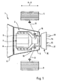
- eine schematische Teilansicht eines Kraftfahrzeugs von oben mit der Abgasanlage nach der Erfindung,
- Fig. 2
- eine Einzelheit der Fig. 1 in größerem Maßstab,
- Fig. 3
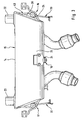
- eine Schrägansicht von links oben eines Schalldämpfers der Abgasanlage,
- Fig. 4
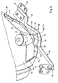
- eine Schrägansicht eines Stützlagers von links oben
- Ein Kraftfahrzeug 1 wird von einer Antriebseinheit 2 über Hinterräder 3 und 4 angetrieben. Die Antriebseinheit 2 - Mittelmotor Bauweise - ist in einen Aggregatträger 5 eines Aufbaus 6 eingesetzt und umfasst eine Brennkraftmaschine 7 mit gegenüberliegenden Zylinderreihen 8 und 9 sowie ein Getriebe 10, das unter Vermittlung von Achswellen 11 und 12 mit den Hinterrädern 3 und 4 zusammenwirkt.
- Die Brennkraftmaschine 7 ist mit einer Abgasanlage 13 verbunden, die hinter dem Aggregatträger 5 mit einem eine Gehäusewandstruktur 14 besitzenden Schalldämpfer 15 versehen ist. Der Schalldämpfer 15 ist quer zur Fahrzeuglängsrichtung A-A eingebaut und unter Vermittlung erster, zweiter und dritter Stützlager 16,17 und 18 an festen Aufbaustrukturen 19,20 und 21 des Aufbaus 6 gehalten. Von der Gehäusewandstruktur I4 weggeführt sind Endrohre 22 und 23, die in Fahrzeuglängsrichtung A-A ausgerichtet sind.
- Die Stützlager 16,17 und 18 sind in Form einer Dreipunktlagerung zueinander angeordnet, wobei das dritte mit einem elastischen Lagerelement 24 versehene Stützlager 18 einerseits an einem vorderen Wandabschnitt 25 der Gehäusewandstruktur 14 und anderseits an einem hinteren Querträger 26 der Aufbaustruktur 21 angeschlossen ist. Darüber hinaus ist das dritte Stützlager 18 unter Zwischenschaltung einer Schraube 27 mit dem Querträger 26 verbunden, und es erstreckt sich in einer Mittellängsebene B-B des Kraftfahrzeugs 1 - Fig. 2 -.
- Das erste Stützlager 16 und das zweite Stützlager 17 verlaufen mit Abstand zu Stirnseiten 28 und 29 des bspw. einen ovalen Querschnitt besitzenden Schalldämpfers 15, wobei diese Stützlager unter Vermittlung zweiarmiger Traghebel 30 und 31 an den Aufbaustrukturen 19 und 20 befestigt sind, welche Traghebel 30 und 31 im wesentlichen baugleich sind. Der federnde Eigenschaften besitzende Traghebel 30 - Fig. 4 - ist mit einem hinteren Hebelarm 32 an einer Pralldämpfereinheit 33 und einem vorderen Hebelarm 34 mit einem Trägerelement 35 des Aggregatträgers 5 verbunden. Dabei sind sowohl die Pralldämpfereinheit 33 wie auch das Trägerelement 35 Bestandteil der Aufbaustruktur 19. Außerdem sind freie Enden 36 und 37 des Traghebels 30 bzw. der Hebelarme 32 und 34 mit Befestigungskonsolen 38 und 39 versehen.
- Gemäß Fig. 4 ist das erste Stützlager 17 mit einem Aufnahmegehäuse 40 für elastische Elemente 41 und 42 versehen, das an dem Traghebel 30 befestigt ist. Hierbei ist das erste Stützlager 17 unter Vermittlung des Aufnahmegehäuses 40 an einer Konsole 43 einer benachbarten Wand 44 der Stirnseite 28 des Schalldämpfers 15 befestigt. Die Konsole 43 ist eine aufrechte Platte 45, die sich in Fahrzeuglängsrichtung A-A erstreckt und von einer vorderen Seite 46 und einer hinteren Seite 47 der Wand 44 weggeführt ist. Darüber hinaus ist die Konsole 43 mit einem Befestigungsabschnitt 48 an eine Einschürung 49 des Aufnahmegehäuses 40 herangeführt. Das Aufnahmegehäuse 40 und die Konsole 41 sind durch geeignete Mittel miteinander verbunden. Schließlich liegt das Aufnahmegehäuse 40 auf einer Auflageplatte 50 auf, die am Traghebel 30 zwischen dem hinteren Hebelarm 32 und dem vorderen Hebelarm 34 angeordnet ist.
Claims (9)
- Kraftfahrzeug (1) mit einer Brennkraftmaschine (7), welche eine Abgasanlage (13) mit einem Schalldämpfer (15) umfasst, der unter Vermittlung mehrerer elastischer Stützlager (16,17,18) an festen Aufbaustrukturen (19,20,21) eines Aufbaus (6) des Kraftfahrzeugs (1) in Lage gehalten ist, wobei wenigstens ein erstes Stützlager (16) und ein zweites Stützlager (17) benachbart von Stirnseiten (28,29) des Schalldämpfers (15) angeordnet sind, wobei das erste Stützlager (16) sowie das zweite Stützlager (17) mit Abstand zu den Stirnseiten (28, 29) des Schalldämpfers (15) verlaufen und unter Vermittlung zweiarmiger Traghebel (30 und 31) an angrenzenden Aufbaustrukturen (22, 23) befestigt sind, dadurch gekennzeichnet, dass mittels eines dritten sich zwischen den Stirnseiten (28, 29) erstreckenden Stützlagers (18) der Schalldämpfer (15) mit einem hinteren Querträger (26) einer Aufbaustruktur (21) verbunden ist.
- Kraftfahrzeug nach Anspruch 1, dadurch gekennzeichnet, dass das erste Stützlager (16) und das zweite Stützlager (17) an Wänden (44) der Stirnseiten (28 und 29) des Schalldämpfers (15) im wesentlichen baugleich ausgeführt sind, wobei zumindest das erste Stützlager (16) ein Aufnahmegehäuse (40) für elastische Elemente (41 und 42) besitzt, das an dem zugehörigen Traghebel (30) befestigt ist.
- Kraftfahrzeug nach Anspruch 2, dadurch gekennzeichnet, dass das erste Stützlager (16) unter Vermittlung des Aufnahmegehäuses (40) an einer Konsole (43) der benachbarten Wand (44) des Schalldämpfers (15) befestigt ist.
- Kraftfahrzeug nach Anspruch 3, dadurch gekennzeichnet, dass die Konsole (43) eine aufrechte Platte (45) ist, die von einer vorderen Seite (46) und einer hintere Seite (47) der Wand (44) weggeführt ist.
- Kraftfahrzeug nach den Ansprüchen 3 und 4, dadurch gekennzeichnet, dass die Konsole (43) mit einem Befestigungsabschnitt (48) an eine Einschnürung (49) des Aufnahmegehäuses (40) herangeführt ist
- Kraftfahrzeug nach Anspruch 2, dadurch gekennzeichnet, dass der Traghebel (30) zwischen dem hinteren Hebelarm (32) und dem vorderen Hebelarm (34) mit einer Auflageplatte (50) für das Aufnahmegehäuse (40) versehen ist.
- Kraftfahrzeug nach Anspruch 6, dadurch gekennzeichnet, dass freie Enden (36 und 37) des hinteren Hebelarms (32) und des vorderen Hebelarms (34) des Traghebels (30) unter Vermittlung von Befestigungskonsolen (38 und 39) an der jeweiligen Aufbaustruktur (19) in Lage gehalten sind.
- Kraftfahrzeug nach einem oder mehreren der vorangehenden Ansprüche, dadurch gekennzeichnet, dass der Traghebel (30 und 31) federnde Eigenschaften besitzt.
- Kraftfahrzeug nach Anspruch 1, dadurch gekennzeichnet, dass das dritte Stützlager (18) in einer Mittellängsebene (B-B) des Schalldämpfers (15) zwischen den ersten Stützlager (16) und dem zweiten Stützlager (17) angeordnet ist.
Applications Claiming Priority (2)
| Application Number | Priority Date | Filing Date | Title |
|---|---|---|---|
| DE2003132940 DE10332940B4 (de) | 2003-07-19 | 2003-07-19 | Abgasanlage für eine Brennkraftmaschine eines Kraftfahrzeugs |
| DE10332940 | 2003-07-19 |
Publications (2)
| Publication Number | Publication Date |
|---|---|
| EP1500543A1 EP1500543A1 (de) | 2005-01-26 |
| EP1500543B1 true EP1500543B1 (de) | 2007-01-03 |
Family
ID=33482983
Family Applications (1)
| Application Number | Title | Priority Date | Filing Date |
|---|---|---|---|
| EP20040010519 Expired - Lifetime EP1500543B1 (de) | 2003-07-19 | 2004-05-04 | Abgasanlage für eine Brennkraftmaschine eines Kraftfahrzeugs |
Country Status (2)
| Country | Link |
|---|---|
| EP (1) | EP1500543B1 (de) |
| DE (2) | DE10332940B4 (de) |
Family Cites Families (5)
| Publication number | Priority date | Publication date | Assignee | Title |
|---|---|---|---|---|
| JPS6082437A (ja) * | 1983-10-14 | 1985-05-10 | Toyota Motor Corp | 排気装置の取付構造 |
| JPH0639903B2 (ja) * | 1988-11-15 | 1994-05-25 | 本田技研工業株式会社 | 発動発電機 |
| DE4408573C2 (de) * | 1993-03-26 | 2000-11-23 | Honda Motor Co Ltd | Hilfsrahmenanordnung und Hilfsrahmen |
| DE19932349C2 (de) * | 1999-07-10 | 2001-08-09 | Porsche Ag | Abgasanlage |
| JP3985491B2 (ja) * | 2001-10-16 | 2007-10-03 | マツダ株式会社 | 排気系構造 |
-
2003
- 2003-07-19 DE DE2003132940 patent/DE10332940B4/de not_active Expired - Fee Related
-
2004
- 2004-05-04 EP EP20040010519 patent/EP1500543B1/de not_active Expired - Lifetime
- 2004-05-04 DE DE200450002502 patent/DE502004002502D1/de not_active Expired - Lifetime
Also Published As
| Publication number | Publication date |
|---|---|
| DE10332940B4 (de) | 2007-07-19 |
| DE10332940A1 (de) | 2005-02-17 |
| DE502004002502D1 (de) | 2007-02-15 |
| EP1500543A1 (de) | 2005-01-26 |
Similar Documents
| Publication | Publication Date | Title |
|---|---|---|
| EP0530594B1 (de) | Fahrschemel für ein Kraftfahrzeug | |
| DE19920051B4 (de) | Fahrschemel für eine Vorderachse eines Kraftfahrzeugs | |
| EP3181390B1 (de) | Fahrzeug mit einem antriebsaggregat und einer aggregatelagerung | |
| DE102012021562B4 (de) | Hilfsrahmen für ein Kraftfahrzeug | |
| EP3158842B1 (de) | Landwirtschaftliches fahrzeug | |
| DE102004028161A1 (de) | Unterfahrschutz für Personenkraftfahrzeuge zur Anordnung unter Längsträgerniveau vor einem Hilfsrahmen oder Achsträger als zusätzliche Crashebene | |
| DE10202956B4 (de) | Tragstruktur für ein Antriebsaggregat eines Kraftfahrzeugs | |
| EP1650055B1 (de) | Antriebsbrücke | |
| DE4423939B4 (de) | Abgassystem für eine Maschine | |
| EP1068979B1 (de) | Abgasanlage | |
| DE4003942A1 (de) | Lenksaeule, insbesondere fuer kraftfahrzeuge | |
| EP1500543B1 (de) | Abgasanlage für eine Brennkraftmaschine eines Kraftfahrzeugs | |
| EP0444016B1 (de) | Triebdrehgestell für elektrische Lokomotiven | |
| EP2133231A2 (de) | Vorrichtung zum Befestigen eines Motors an einem Rahmen eines landwirtschaftlichen oder industriellen Nutzfahrzeugs | |
| DE102018202354B4 (de) | Federeinrichtung für eine Kraftfahrzeug-Radaufhängung mit zumindest einer Blattfeder sowie Verfahren zur Einstellung der Federrate besagter Blattfeder | |
| DE102008023496A1 (de) | Unterer Aufbau für ein Fahrzeug | |
| EP1040041A1 (de) | Fahrzeug mit einem rahmen | |
| DE10313902B4 (de) | Dämpfungsvorrichtung | |
| DE585115C (de) | Kraftfahrzeug mit Rohrrahmen | |
| DE4307998C2 (de) | Vorrichtung zum Vermindern von Karosserieeigenschwingungen | |
| DE19915635A1 (de) | Schwingungssystem für die Dämpfung und/oder Tilgung der Schwingungen einer Kraftfahrzeugachse | |
| DE102020107781A1 (de) | Einrichtung zur Schwingungstilgung an einem Fahrwerkslenker eines Kraftfahrzeugs | |
| DE102018219598A1 (de) | Aggregateträgeranordnung für ein Kraftfahrzeug sowie Verfahren zum Montieren des Kraftfahrzeugs | |
| DE313442C (de) | ||
| DE102021214942A1 (de) | Hilfsrahmen für ein Kraftfahrzeug, Aggregatlagersystem und Fahrzeug |
Legal Events
| Date | Code | Title | Description |
|---|---|---|---|
| PUAI | Public reference made under article 153(3) epc to a published international application that has entered the european phase |
Free format text: ORIGINAL CODE: 0009012 |
|
| AK | Designated contracting states |
Kind code of ref document: A1 Designated state(s): AT BE BG CH CY CZ DE DK EE ES FI FR GB GR HU IE IT LI LU MC NL PL PT RO SE SI SK TR |
|
| AX | Request for extension of the european patent |
Extension state: AL HR LT LV MK |
|
| 17P | Request for examination filed |
Effective date: 20050726 |
|
| AKX | Designation fees paid |
Designated state(s): DE FR GB IT |
|
| GRAP | Despatch of communication of intention to grant a patent |
Free format text: ORIGINAL CODE: EPIDOSNIGR1 |
|
| GRAS | Grant fee paid |
Free format text: ORIGINAL CODE: EPIDOSNIGR3 |
|
| GRAA | (expected) grant |
Free format text: ORIGINAL CODE: 0009210 |
|
| AK | Designated contracting states |
Kind code of ref document: B1 Designated state(s): DE FR GB IT |
|
| REG | Reference to a national code |
Ref country code: GB Ref legal event code: FG4D Free format text: NOT ENGLISH |
|
| REF | Corresponds to: |
Ref document number: 502004002502 Country of ref document: DE Date of ref document: 20070215 Kind code of ref document: P |
|
| ET | Fr: translation filed | ||
| PLBE | No opposition filed within time limit |
Free format text: ORIGINAL CODE: 0009261 |
|
| STAA | Information on the status of an ep patent application or granted ep patent |
Free format text: STATUS: NO OPPOSITION FILED WITHIN TIME LIMIT |
|
| 26N | No opposition filed |
Effective date: 20071005 |
|
| REG | Reference to a national code |
Ref country code: FR Ref legal event code: TP |
|
| REG | Reference to a national code |
Ref country code: FR Ref legal event code: CD |
|
| REG | Reference to a national code |
Ref country code: FR Ref legal event code: TP |
|
| REG | Reference to a national code |
Ref country code: GB Ref legal event code: 732E Free format text: REGISTERED BETWEEN 20110310 AND 20110316 |
|
| REG | Reference to a national code |
Ref country code: GB Ref legal event code: 732E Free format text: REGISTERED BETWEEN 20110331 AND 20110406 |
|
| PGFP | Annual fee paid to national office [announced via postgrant information from national office to epo] |
Ref country code: FR Payment date: 20110607 Year of fee payment: 8 |
|
| PGFP | Annual fee paid to national office [announced via postgrant information from national office to epo] |
Ref country code: GB Payment date: 20110520 Year of fee payment: 8 |
|
| PGFP | Annual fee paid to national office [announced via postgrant information from national office to epo] |
Ref country code: DE Payment date: 20110426 Year of fee payment: 8 |
|
| PGFP | Annual fee paid to national office [announced via postgrant information from national office to epo] |
Ref country code: IT Payment date: 20070531 Year of fee payment: 4 |
|
| GBPC | Gb: european patent ceased through non-payment of renewal fee |
Effective date: 20120504 |
|
| REG | Reference to a national code |
Ref country code: FR Ref legal event code: ST Effective date: 20130131 |
|
| REG | Reference to a national code |
Ref country code: DE Ref legal event code: R119 Ref document number: 502004002502 Country of ref document: DE Effective date: 20121201 |
|
| PG25 | Lapsed in a contracting state [announced via postgrant information from national office to epo] |
Ref country code: FR Free format text: LAPSE BECAUSE OF NON-PAYMENT OF DUE FEES Effective date: 20120531 Ref country code: GB Free format text: LAPSE BECAUSE OF NON-PAYMENT OF DUE FEES Effective date: 20120504 |
|
| PG25 | Lapsed in a contracting state [announced via postgrant information from national office to epo] |
Ref country code: DE Free format text: LAPSE BECAUSE OF NON-PAYMENT OF DUE FEES Effective date: 20121201 |