EP1500543A1 - Abgasanlage für eine Brennkraftmaschine eines Kraftfahrzeugs - Google Patents
Abgasanlage für eine Brennkraftmaschine eines Kraftfahrzeugs Download PDFInfo
- Publication number
- EP1500543A1 EP1500543A1 EP04010519A EP04010519A EP1500543A1 EP 1500543 A1 EP1500543 A1 EP 1500543A1 EP 04010519 A EP04010519 A EP 04010519A EP 04010519 A EP04010519 A EP 04010519A EP 1500543 A1 EP1500543 A1 EP 1500543A1
- Authority
- EP
- European Patent Office
- Prior art keywords
- exhaust system
- support bearing
- support
- muffler
- lever
- Prior art date
- Legal status (The legal status is an assumption and is not a legal conclusion. Google has not performed a legal analysis and makes no representation as to the accuracy of the status listed.)
- Granted
Links
Images

Classifications
-
- F—MECHANICAL ENGINEERING; LIGHTING; HEATING; WEAPONS; BLASTING
- F01—MACHINES OR ENGINES IN GENERAL; ENGINE PLANTS IN GENERAL; STEAM ENGINES
- F01N—GAS-FLOW SILENCERS OR EXHAUST APPARATUS FOR MACHINES OR ENGINES IN GENERAL; GAS-FLOW SILENCERS OR EXHAUST APPARATUS FOR INTERNAL-COMBUSTION ENGINES
- F01N13/00—Exhaust or silencing apparatus characterised by constructional features
- F01N13/18—Construction facilitating manufacture, assembly, or disassembly
- F01N13/1805—Fixing exhaust manifolds, exhaust pipes or pipe sections to each other, to engine or to vehicle body
- F01N13/1811—Fixing exhaust manifolds, exhaust pipes or pipe sections to each other, to engine or to vehicle body with means permitting relative movement, e.g. compensation of thermal expansion or vibration
- F01N13/1822—Fixing exhaust manifolds, exhaust pipes or pipe sections to each other, to engine or to vehicle body with means permitting relative movement, e.g. compensation of thermal expansion or vibration for fixing exhaust pipes or devices to vehicle body
-
- B—PERFORMING OPERATIONS; TRANSPORTING
- B60—VEHICLES IN GENERAL
- B60K—ARRANGEMENT OR MOUNTING OF PROPULSION UNITS OR OF TRANSMISSIONS IN VEHICLES; ARRANGEMENT OR MOUNTING OF PLURAL DIVERSE PRIME-MOVERS IN VEHICLES; AUXILIARY DRIVES FOR VEHICLES; INSTRUMENTATION OR DASHBOARDS FOR VEHICLES; ARRANGEMENTS IN CONNECTION WITH COOLING, AIR INTAKE, GAS EXHAUST OR FUEL SUPPLY OF PROPULSION UNITS IN VEHICLES
- B60K13/00—Arrangement in connection with combustion air intake or gas exhaust of propulsion units
- B60K13/04—Arrangement in connection with combustion air intake or gas exhaust of propulsion units concerning exhaust
Definitions
- the invention relates to an exhaust system of a motor vehicle according to the Preamble of claim 1.
- the US 4,961,403 shows a transverse to the vehicle longitudinal direction of a motor vehicle arranged silencer, the longitudinal sides by means of hangers and support bearings a frame structure surrounding the muffler is attached.
- a motor vehicle 1 is driven by a drive unit 2 via rear wheels 3 and 4 driven.
- the drive unit 2 - mid-engine construction - is in an aggregate carrier.
- a structure 6 is used and includes an internal combustion engine 7 with opposite rows of cylinders 8 and 9 and a transmission 10, the mediation of axle shafts 11 and 12 cooperates with the rear wheels 3 and 4.
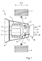
- the internal combustion engine 7 is connected to an exhaust system 13, behind the Aggregate support 5 with a housing wall structure 14 owning a silencer 15th is provided.
- the muffler 15 is installed transversely to the vehicle longitudinal direction A-A and under mediation of first, second and third support bearings 16,17 and 18 at fixed Built-up structures 19,20 and 21 of the structure 6 held. From the housing wall structure I4 are led tailpipes 22 and 23, which are aligned in the vehicle longitudinal direction A-A are.
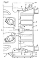
- the support bearings 16,17 and 18 are in the form of a three-point bearing to each other arranged, wherein the third provided with an elastic bearing member 24 Support bearing 18 on the one hand to a front wall portion 25 of the housing wall structure 14 and on the other hand on a rear cross member 26 of the body structure 21st connected.
- the third support bearing 18 with interposition a screw 27 connected to the cross member 26, and it extends in one Central longitudinal plane B-B of the motor vehicle 1 - Fig. 2 -.
- the first support bearing 16 and the second support bearing 17 extend at a distance End faces 28 and 29 of the example.
- An oval cross section owning silencer 15 wherein these support bearings under mediation two-armed support lever 30 and 31 to the Structural structures 19 and 20 are fixed, which support lever 30 and 31 substantially are identical.
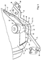
- the resilient properties possessing support lever 30 - Fig. 4 - is with a rear lever arm 32 on an impact damper unit 33 and a front Lever arm 34 is connected to a carrier element 35 of the unit carrier 5.
- free ends 36 and 37 of the support lever 30 and the Lever arms 32 and 34 provided with mounting brackets 38 and 39.
- first support bearing 17 through the intermediary of the receiving housing 40 to a console 43rd an adjacent wall 44 of the end face 28 of the muffler 15 attached.
- the Console 43 is an upright plate 45 which extends in the vehicle longitudinal direction A-A and led away from a front side 46 and a rear side 47 of the wall 44.
- the console 43 with a mounting portion 48 to a Einschürung 49 of the receiving housing 40 introduced.
- the receiving housing 40 and the console 41 are interconnected by suitable means.
- Receiving housing 40 on a support plate 50 which on the support lever 30 between the rear lever arm 32 and the front lever arm 34 is arranged.
Landscapes
- Engineering & Computer Science (AREA)
- Chemical & Material Sciences (AREA)
- Combustion & Propulsion (AREA)
- Mechanical Engineering (AREA)
- Transportation (AREA)
- General Engineering & Computer Science (AREA)
- Exhaust Silencers (AREA)
- Cooling, Air Intake And Gas Exhaust, And Fuel Tank Arrangements In Propulsion Units (AREA)
Abstract
Description
- Fig. 1
- eine schematische Teilansicht eines Kraftfahrzeugs von oben mit der Abgasanlage nach der Erfindung,
- Fig. 2
- eine Einzelheit der Fig. 1 in größerem Maßstab,
- Fig. 3
- eine Schrägansicht von links oben eines Schalldämpfers der Abgasanlage,
- Fig. 4
- eine Schrägansicht eines Stützlagers von links oben
Claims (9)
- Abgasanlage für eine Brennkraftmaschine eines Kraftfahrzeugs, welche Abgasanlage einen Schalldämpfer umfasst, der unter Vermittlung mehrer elastischer Stützlager an festen Aufbaustrukturen eines Aufbaus des Kraftfahrzeugs in Lage gehalten ist, wobei wenigstens ein erstes Stützlager und ein zweites Stützlager benachbart von Stirnseiten des Schalldämpfer angeordnet sind, dadurch gekennzeichnet, dass mittels eines dritten sich zwischen den Stirnseiten (28 und 29) erstreckenden Stützlagers (18) der Schalldämpfer (15) mit einer Aufbaustruktur (21) verbunden ist und dass das erste Stützlager (16) sowie das zweite Stützlager (17) mit Abstand zu den Stirnseiten (28 und 29) des Schalldämpfers (15) verlaufen und unter Vermittlung zweiarmiger Traghebel (30 du 31) an angrenzenden Aufbaustrukturen (22 und 23) befestigt sind.
- Abgasanlage nach Anspruch 1, dadurch gekennzeichnet, dass das erste Stützlager (16) und das zweite Stützlager (17) an Wänden (44) der Stirnseiten (28 und 29) des Schalldämpfers (15) im wesentlichen baugleich ausgeführt sind, wobei zumindest das erste Stützlager (16) ein Aufnahmegehäuse (40) für elastische Elemente (41 und 42) besitzt, das an dem zugehörigen Traghebel (30) befestigt ist.
- Abgasanlage nach Anspruch 2, dadurch gekennzeichnet, dass das erste Stützlager (16) unter Vermittlung des Aufnahmegehäuses (40) an einer Konsole (43) der benachbarten Wand (44) des Schalldämpfers (15) befestigt ist.
- Abgasanlage nach Anspruch 3, dadurch gekennzeichnet, dass die Konsole (43) eine aufrechte Platte (45) ist, die von einer vorderen Seite (46) und einer hintere Seite (47) der Wand (44) weggeführt ist.
- Abgasanlage nach den Ansprüchen 3 und 4, dadurch gekennzeichnet, dass die Konsole (43) mit einem Befestigungsabschnitt (48) an eine Einschnürung (49) des Aufnahmegehäuses (40) herangeführt ist
- Abgasanlage nach Anspruch 2, dadurch gekennzeichnet, dass der Traghebel (30) zwischen dem hinteren Hebelarm (32) und dem vorderen Hebelarm (34) mit einer Auflageplatte (50) für das Aufnahmegehäuse (40) versehen ist.
- Abgasanlage nach Anspruch 6, dadurch gekennzeichnet, dass freie Enden (36 und 37) des hinteren Hebelarms (32) und des vorderen Hebelarms (34) des Traghebels (30) unter Vermittlung von Befestigungskonsolen (38 und 39) an der jeweiligen Aufbaustruktur (19) in Lage gehalten sind.
- Abgasanlage nach einem oder mehreren der vorangehenden Ansprüche, dadurch gekennzeichnet, dass der Taghebel (30 und 31) federnde Eigenschaften besitzt.
- Abgasanlage nach Anspruch 1, dadurch gekennzeichnet, dass das dritte Stützlager (18) in einer Mittellängsebene (B-B) des Schalldämpfers (15) zwischen den ersten Stützlager (16) und dem zweiten Stützlager (17) angeordnet ist.
Applications Claiming Priority (2)
| Application Number | Priority Date | Filing Date | Title |
|---|---|---|---|
| DE2003132940 DE10332940B4 (de) | 2003-07-19 | 2003-07-19 | Abgasanlage für eine Brennkraftmaschine eines Kraftfahrzeugs |
| DE10332940 | 2003-07-19 |
Publications (2)
| Publication Number | Publication Date |
|---|---|
| EP1500543A1 true EP1500543A1 (de) | 2005-01-26 |
| EP1500543B1 EP1500543B1 (de) | 2007-01-03 |
Family
ID=33482983
Family Applications (1)
| Application Number | Title | Priority Date | Filing Date |
|---|---|---|---|
| EP20040010519 Expired - Lifetime EP1500543B1 (de) | 2003-07-19 | 2004-05-04 | Abgasanlage für eine Brennkraftmaschine eines Kraftfahrzeugs |
Country Status (2)
| Country | Link |
|---|---|
| EP (1) | EP1500543B1 (de) |
| DE (2) | DE10332940B4 (de) |
Citations (3)
| Publication number | Priority date | Publication date | Assignee | Title |
|---|---|---|---|---|
| US4596304A (en) * | 1983-10-14 | 1986-06-24 | Toyota Jidosha Kabushiki Kaisha | Exhaust support system |
| EP1068979A2 (de) * | 1999-07-10 | 2001-01-17 | Dr.Ing. h.c.F. Porsche Aktiengesellschaft | Abgasanlage |
| JP2003120282A (ja) * | 2001-10-16 | 2003-04-23 | Mazda Motor Corp | 排気系構造 |
Family Cites Families (2)
| Publication number | Priority date | Publication date | Assignee | Title |
|---|---|---|---|---|
| JPH0639903B2 (ja) * | 1988-11-15 | 1994-05-25 | 本田技研工業株式会社 | 発動発電機 |
| DE4408573C2 (de) * | 1993-03-26 | 2000-11-23 | Honda Motor Co Ltd | Hilfsrahmenanordnung und Hilfsrahmen |
-
2003
- 2003-07-19 DE DE2003132940 patent/DE10332940B4/de not_active Expired - Fee Related
-
2004
- 2004-05-04 EP EP20040010519 patent/EP1500543B1/de not_active Expired - Lifetime
- 2004-05-04 DE DE200450002502 patent/DE502004002502D1/de not_active Expired - Lifetime
Patent Citations (3)
| Publication number | Priority date | Publication date | Assignee | Title |
|---|---|---|---|---|
| US4596304A (en) * | 1983-10-14 | 1986-06-24 | Toyota Jidosha Kabushiki Kaisha | Exhaust support system |
| EP1068979A2 (de) * | 1999-07-10 | 2001-01-17 | Dr.Ing. h.c.F. Porsche Aktiengesellschaft | Abgasanlage |
| JP2003120282A (ja) * | 2001-10-16 | 2003-04-23 | Mazda Motor Corp | 排気系構造 |
Non-Patent Citations (1)
| Title |
|---|
| PATENT ABSTRACTS OF JAPAN vol. 2003, no. 08 6 August 2003 (2003-08-06) * |
Also Published As
| Publication number | Publication date |
|---|---|
| DE10332940B4 (de) | 2007-07-19 |
| DE10332940A1 (de) | 2005-02-17 |
| EP1500543B1 (de) | 2007-01-03 |
| DE502004002502D1 (de) | 2007-02-15 |
Similar Documents
| Publication | Publication Date | Title |
|---|---|---|
| EP0530594B1 (de) | Fahrschemel für ein Kraftfahrzeug | |
| EP3181390B1 (de) | Fahrzeug mit einem antriebsaggregat und einer aggregatelagerung | |
| DE102012021562B4 (de) | Hilfsrahmen für ein Kraftfahrzeug | |
| EP1837268A2 (de) | Hilfsrahmen für Kraftfahrzeuge sowie Verfahren zur Montage eines Antriebsaggregats auf einem solchen Hilfsrahmen | |
| EP3158842B1 (de) | Landwirtschaftliches fahrzeug | |
| DE10202956B4 (de) | Tragstruktur für ein Antriebsaggregat eines Kraftfahrzeugs | |
| EP1650055B1 (de) | Antriebsbrücke | |
| DE102017214955A1 (de) | Aggregatelagerung für ein zweispuriges Fahrzeug | |
| DE4423939B4 (de) | Abgassystem für eine Maschine | |
| EP1068979B1 (de) | Abgasanlage | |
| DE4003942A1 (de) | Lenksaeule, insbesondere fuer kraftfahrzeuge | |
| DE7828716U1 (de) | Vorrichtung zur geraeuschdaempfung von servolenkungen | |
| EP1500543A1 (de) | Abgasanlage für eine Brennkraftmaschine eines Kraftfahrzeugs | |
| DE2843917C2 (de) | Trieb- und Fahrwerksanordnung für Kraftfahrzeuge | |
| DE102006013547B4 (de) | Hilfsrahmen für Kraftfahrzeuge sowie ein Verfahren zur Montage von Antriebsaggregaten von Kraftfahrzeugen auf solchen Hilfsrahmen | |
| DE10233826A1 (de) | Befestigungsanordnung eines Feder- und/oder Dämpferelementes an einem Hohlträger einer Kraftwagenkarosserie | |
| DE68902010T2 (de) | Blattfederbefestigung. | |
| WO2016015919A1 (de) | Modularer hilfsrahmen für eine radachse sowie herstellungsverfahren eines hilfsrahmens | |
| DE102020128033B4 (de) | Stützteilanordnung, Montagebaukasten und Montageverfahren | |
| EP0887247B1 (de) | Verfahren zur Anbindung eines Aggregatenquerträgers an eine Vorbaustruktur | |
| DE2314399A1 (de) | Kraftfahrzeug | |
| DE4307998C2 (de) | Vorrichtung zum Vermindern von Karosserieeigenschwingungen | |
| DE102013210235A1 (de) | Drehmomentstütze für ein Schienenfahrzeug | |
| DE585115C (de) | Kraftfahrzeug mit Rohrrahmen | |
| DE102010054086A1 (de) | Vorderachshilfsrahmen für ein Kraftfahrzeug sowie Kraftfahrzeug |
Legal Events
| Date | Code | Title | Description |
|---|---|---|---|
| PUAI | Public reference made under article 153(3) epc to a published international application that has entered the european phase |
Free format text: ORIGINAL CODE: 0009012 |
|
| AK | Designated contracting states |
Kind code of ref document: A1 Designated state(s): AT BE BG CH CY CZ DE DK EE ES FI FR GB GR HU IE IT LI LU MC NL PL PT RO SE SI SK TR |
|
| AX | Request for extension of the european patent |
Extension state: AL HR LT LV MK |
|
| 17P | Request for examination filed |
Effective date: 20050726 |
|
| AKX | Designation fees paid |
Designated state(s): DE FR GB IT |
|
| GRAP | Despatch of communication of intention to grant a patent |
Free format text: ORIGINAL CODE: EPIDOSNIGR1 |
|
| GRAS | Grant fee paid |
Free format text: ORIGINAL CODE: EPIDOSNIGR3 |
|
| GRAA | (expected) grant |
Free format text: ORIGINAL CODE: 0009210 |
|
| AK | Designated contracting states |
Kind code of ref document: B1 Designated state(s): DE FR GB IT |
|
| REG | Reference to a national code |
Ref country code: GB Ref legal event code: FG4D Free format text: NOT ENGLISH |
|
| REF | Corresponds to: |
Ref document number: 502004002502 Country of ref document: DE Date of ref document: 20070215 Kind code of ref document: P |
|
| ET | Fr: translation filed | ||
| PLBE | No opposition filed within time limit |
Free format text: ORIGINAL CODE: 0009261 |
|
| STAA | Information on the status of an ep patent application or granted ep patent |
Free format text: STATUS: NO OPPOSITION FILED WITHIN TIME LIMIT |
|
| 26N | No opposition filed |
Effective date: 20071005 |
|
| REG | Reference to a national code |
Ref country code: FR Ref legal event code: TP |
|
| REG | Reference to a national code |
Ref country code: FR Ref legal event code: CD |
|
| REG | Reference to a national code |
Ref country code: FR Ref legal event code: TP |
|
| REG | Reference to a national code |
Ref country code: GB Ref legal event code: 732E Free format text: REGISTERED BETWEEN 20110310 AND 20110316 |
|
| REG | Reference to a national code |
Ref country code: GB Ref legal event code: 732E Free format text: REGISTERED BETWEEN 20110331 AND 20110406 |
|
| PGFP | Annual fee paid to national office [announced via postgrant information from national office to epo] |
Ref country code: FR Payment date: 20110607 Year of fee payment: 8 |
|
| PGFP | Annual fee paid to national office [announced via postgrant information from national office to epo] |
Ref country code: GB Payment date: 20110520 Year of fee payment: 8 |
|
| PGFP | Annual fee paid to national office [announced via postgrant information from national office to epo] |
Ref country code: DE Payment date: 20110426 Year of fee payment: 8 |
|
| PGFP | Annual fee paid to national office [announced via postgrant information from national office to epo] |
Ref country code: IT Payment date: 20070531 Year of fee payment: 4 |
|
| GBPC | Gb: european patent ceased through non-payment of renewal fee |
Effective date: 20120504 |
|
| REG | Reference to a national code |
Ref country code: FR Ref legal event code: ST Effective date: 20130131 |
|
| REG | Reference to a national code |
Ref country code: DE Ref legal event code: R119 Ref document number: 502004002502 Country of ref document: DE Effective date: 20121201 |
|
| PG25 | Lapsed in a contracting state [announced via postgrant information from national office to epo] |
Ref country code: FR Free format text: LAPSE BECAUSE OF NON-PAYMENT OF DUE FEES Effective date: 20120531 Ref country code: GB Free format text: LAPSE BECAUSE OF NON-PAYMENT OF DUE FEES Effective date: 20120504 |
|
| PG25 | Lapsed in a contracting state [announced via postgrant information from national office to epo] |
Ref country code: DE Free format text: LAPSE BECAUSE OF NON-PAYMENT OF DUE FEES Effective date: 20121201 |