EP1500543B1 - Système d'échappement pour un moteur à combustion interne d'un véhicule automobile - Google Patents
Système d'échappement pour un moteur à combustion interne d'un véhicule automobile Download PDFInfo
- Publication number
- EP1500543B1 EP1500543B1 EP20040010519 EP04010519A EP1500543B1 EP 1500543 B1 EP1500543 B1 EP 1500543B1 EP 20040010519 EP20040010519 EP 20040010519 EP 04010519 A EP04010519 A EP 04010519A EP 1500543 B1 EP1500543 B1 EP 1500543B1
- Authority
- EP
- European Patent Office
- Prior art keywords
- motor vehicle
- support bearing
- vehicle according
- silencer
- support
- Prior art date
- Legal status (The legal status is an assumption and is not a legal conclusion. Google has not performed a legal analysis and makes no representation as to the accuracy of the status listed.)
- Expired - Lifetime
Links
Images

Classifications
-
- F—MECHANICAL ENGINEERING; LIGHTING; HEATING; WEAPONS; BLASTING
- F01—MACHINES OR ENGINES IN GENERAL; ENGINE PLANTS IN GENERAL; STEAM ENGINES
- F01N—GAS-FLOW SILENCERS OR EXHAUST APPARATUS FOR MACHINES OR ENGINES IN GENERAL; GAS-FLOW SILENCERS OR EXHAUST APPARATUS FOR INTERNAL-COMBUSTION ENGINES
- F01N13/00—Exhaust or silencing apparatus characterised by constructional features
- F01N13/18—Construction facilitating manufacture, assembly, or disassembly
- F01N13/1805—Fixing exhaust manifolds, exhaust pipes or pipe sections to each other, to engine or to vehicle body
- F01N13/1811—Fixing exhaust manifolds, exhaust pipes or pipe sections to each other, to engine or to vehicle body with means permitting relative movement, e.g. compensation of thermal expansion or vibration
- F01N13/1822—Fixing exhaust manifolds, exhaust pipes or pipe sections to each other, to engine or to vehicle body with means permitting relative movement, e.g. compensation of thermal expansion or vibration for fixing exhaust pipes or devices to vehicle body
-
- B—PERFORMING OPERATIONS; TRANSPORTING
- B60—VEHICLES IN GENERAL
- B60K—ARRANGEMENT OR MOUNTING OF PROPULSION UNITS OR OF TRANSMISSIONS IN VEHICLES; ARRANGEMENT OR MOUNTING OF PLURAL DIVERSE PRIME-MOVERS IN VEHICLES; AUXILIARY DRIVES FOR VEHICLES; INSTRUMENTATION OR DASHBOARDS FOR VEHICLES; ARRANGEMENTS IN CONNECTION WITH COOLING, AIR INTAKE, GAS EXHAUST OR FUEL SUPPLY OF PROPULSION UNITS IN VEHICLES
- B60K13/00—Arrangement in connection with combustion air intake or gas exhaust of propulsion units
- B60K13/04—Arrangement in connection with combustion air intake or gas exhaust of propulsion units concerning exhaust
Definitions
- the invention relates to an exhaust system of a motor vehicle according to the preamble of patent claim 1.
- the generic JP 2003-120282 A describes an exhaust system for an internal combustion engine, comprising a muffler, which is held using a first support device and a second support device on fixed structures of the vehicle in structure. Both support devices are each arranged laterally spaced from the muffler and fastened by the mediation of two-armed support lever to the adjacent body structures.
- EP 1 068 979 A2 discloses an exhaust system with a muffler, which by means of a suspension device, which has a first and a second support device. Both support devices are connected to each other by means of a support bracket, which is attached to the transmission of the vehicle.
- the US 4,961,403 shows a transversely to the vehicle longitudinal direction of a motor vehicle arranged muffler, which is attached to longitudinal sides by means of hanger and support bearing on a surrounding the muffler frame structure.
- the bearings should be characterized by simple construction and easy to manufacture components
- the advantages achieved by the invention are to be seen in the fact that the muffler of the exhaust system is held by means of bearings in such a way that the loads occurring are received technically advantageous. This is further assisted by the two-armed support levers of the support bearings, which stand out because by far running the front sides of the muffler, can be easily installed between the muffler and adjacent body structures of the motor vehicle. In addition, the components of these support bearings can be produced in an economical manner.
- a motor vehicle 1 is driven by a drive unit 2 via rear wheels 3 and 4.
- the drive unit 2 - mid-engine design - is used in an aggregate carrier 5 of a body 6 and includes an internal combustion engine 7 with opposite rows of cylinders 8 and 9 and a transmission 10, which interacts with the rear wheels 3 and 4 through the intermediary of axle shafts 11 and 12.
- the internal combustion engine 7 is connected to an exhaust system 13, which is provided behind the unit carrier 5 with a housing 15 having a housing wall structure muffler.
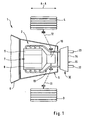
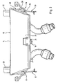
- the muffler 15 is installed transversely to the vehicle longitudinal direction AA and held by the intermediary of first, second and third support bearings 16, 17 and 18 on fixed body structures 19, 20 and 21 of the body 6. Lead away from the housing wall structure I4 tailpipes 22 and 23, which are aligned in the vehicle longitudinal direction AA.
- the support bearings 16,17 and 18 are arranged in the form of a three-point bearing to each other, wherein the third provided with an elastic bearing member 24 support bearing 18 is connected on the one hand to a front wall portion 25 of the housing wall structure 14 and on the other hand to a rear cross member 26 of the body structure 21.
- the third support bearing 18 is connected with the interposition of a screw 27 to the cross member 26, and it extends in a central longitudinal plane B-B of the motor vehicle 1 - Fig. 2 -.
- the first support bearing 16 and the second support bearing 17 extend at a distance from end faces 28 and 29 of, for example, an oval cross-section possessing muffler 15, these support bearings are attached by means of two-armed support lever 30 and 31 on the body structures 19 and 20, which support lever 30 and 31 are substantially identical.
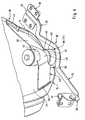
- the resilient properties possessing support lever 30 - Fig. 4 - is connected to a rear lever arm 32 on a shock absorber unit 33 and a front lever arm 34 with a support member 35 of the unit carrier 5.
- both the impact damper unit 33 as well as the support member 35 are part of the body structure 19.
- free ends 36 and 37 of the support lever 30 and the lever arms 32 and 34 are provided with mounting brackets 38 and 39.
- the first support bearing 17 is provided with a receiving housing 40 for elastic members 41 and 42 which is fixed to the support lever 30.
- the first support bearing 17 is fixed by means of the receiving housing 40 to a bracket 43 of an adjacent wall 44 of the end face 28 of the muffler 15.
- the console 43 is an upright plate 45 which extends in the vehicle longitudinal direction A-A and is guided away from a front side 46 and a rear side 47 of the wall 44.
- the console 43 is brought with a mounting portion 48 to a Einschürung 49 of the receiving housing 40.
- the receiving housing 40 and the bracket 41 are interconnected by suitable means.
- the receiving housing 40 rests on a support plate 50, which is arranged on the support lever 30 between the rear lever arm 32 and the front lever arm 34.
Landscapes
- Engineering & Computer Science (AREA)
- Chemical & Material Sciences (AREA)
- Combustion & Propulsion (AREA)
- Mechanical Engineering (AREA)
- Transportation (AREA)
- General Engineering & Computer Science (AREA)
- Exhaust Silencers (AREA)
- Cooling, Air Intake And Gas Exhaust, And Fuel Tank Arrangements In Propulsion Units (AREA)
Claims (9)
- Véhicule automobile (1) comprenant un moteur à combustion interne (7), lequel comporte un système d'échappement (13) doté d'un silencieux (15), qui est immobilisé sur des structures de carrosserie fixes (19, 20, 21) d'une carrosserie (6) du véhicule automobile (1) par l'intermédiaire de plusieurs paliers d'appui élastiques (16, 17, 18), au moins un premier palier d'appui (16) et un deuxième palier d'appui (17) étant disposés au voisinage des côtés frontaux (28, 29) du silencieux (15), le premier palier d'appui (16) ainsi que le deuxième palier d'appui (17) s'étendant à distance des côtés frontaux (28, 29) du silencieux (15) et étant fixés aux structures de carrosserie adjacentes (22, 23) par l'intermédiaire de leviers de support à deux bras (30 et 31), caractérisé en ce que le silencieux (15) est relié à une traverse arrière (26) d'une structure de carrosserie (21) au moyen d'un troisième palier d'appui (18) s'étendant entre les côtés frontaux (28, 29).
- Véhicule automobile selon la revendication 1, caractérisé en ce que le premier palier d'appui (16) et le deuxième palier d'appui (17) sur les parois (44) des côtés frontaux (28 et 29) du silencieux (15) présentent sensiblement la même conception, au moins le premier palier d'appui (16) possédant un boîtier de réception (40) pour des éléments élastiques (41 et 42), lequel boîtier est fixé au levier de support (30) associé.
- Véhicule automobile selon la revendication 2, caractérisé en ce que le premier palier d'appui (16), est fixé à une console (43) de la paroi voisine (44) du silencieux (15) par l'intermédiaire du boîtier de réception (40).
- Véhicule automobile selon la revendication 3, caractérisé en ce que la console (43) est une plaque droite (45), qui est éloignée d'un côté avant (46) et d'un côté arrière (47) de la paroi (44).
- Véhicule automobile selon l'une quelconque des revendications 3 et 4, caractérisé en ce que la console (43) dotée d'une section de fixation (48) est approchée d'un rétrécissement (49) du boîtier de réception (40).
- Véhicule automobile selon la revendication 2, caractérisé en ce que le levier de support (30) entre le bras de levier arrière (32) et le bras de levier avant (34) est pourvu d'une plaque d'appui (50) pour le boîtier de réception (40).
- Véhicule automobile selon la revendication 6, caractérisé en ce que les extrémités libres (36 et 37) du bras de levier arrière (32) et du bras de levier avant (34) du levier de support (30) sont immobilisées sur la structure de carrosserie (19) respective par l'intermédiaire de consoles de fixation (38 et 39).
- Véhicule automobile selon l'une ou plusieurs des revendications précédentes, caractérisé en ce que le levier de support (30 et 31) possède des propriétés élastiques.
- Véhicule automobile selon la revendication 1, caractérisé en ce que le troisième palier (18) est disposé dans un plan longitudinal médian (B-B) du silencieux (15) entre les premiers paliers d'appui (16) et le deuxième palier d'appui (17).
Applications Claiming Priority (2)
| Application Number | Priority Date | Filing Date | Title |
|---|---|---|---|
| DE10332940 | 2003-07-19 | ||
| DE2003132940 DE10332940B4 (de) | 2003-07-19 | 2003-07-19 | Abgasanlage für eine Brennkraftmaschine eines Kraftfahrzeugs |
Publications (2)
| Publication Number | Publication Date |
|---|---|
| EP1500543A1 EP1500543A1 (fr) | 2005-01-26 |
| EP1500543B1 true EP1500543B1 (fr) | 2007-01-03 |
Family
ID=33482983
Family Applications (1)
| Application Number | Title | Priority Date | Filing Date |
|---|---|---|---|
| EP20040010519 Expired - Lifetime EP1500543B1 (fr) | 2003-07-19 | 2004-05-04 | Système d'échappement pour un moteur à combustion interne d'un véhicule automobile |
Country Status (2)
| Country | Link |
|---|---|
| EP (1) | EP1500543B1 (fr) |
| DE (2) | DE10332940B4 (fr) |
Family Cites Families (5)
| Publication number | Priority date | Publication date | Assignee | Title |
|---|---|---|---|---|
| JPS6082437A (ja) * | 1983-10-14 | 1985-05-10 | Toyota Motor Corp | 排気装置の取付構造 |
| JPH0639903B2 (ja) * | 1988-11-15 | 1994-05-25 | 本田技研工業株式会社 | 発動発電機 |
| DE4408573C2 (de) * | 1993-03-26 | 2000-11-23 | Honda Motor Co Ltd | Hilfsrahmenanordnung und Hilfsrahmen |
| DE19932349C2 (de) * | 1999-07-10 | 2001-08-09 | Porsche Ag | Abgasanlage |
| JP3985491B2 (ja) * | 2001-10-16 | 2007-10-03 | マツダ株式会社 | 排気系構造 |
-
2003
- 2003-07-19 DE DE2003132940 patent/DE10332940B4/de not_active Expired - Fee Related
-
2004
- 2004-05-04 EP EP20040010519 patent/EP1500543B1/fr not_active Expired - Lifetime
- 2004-05-04 DE DE200450002502 patent/DE502004002502D1/de not_active Expired - Lifetime
Also Published As
| Publication number | Publication date |
|---|---|
| EP1500543A1 (fr) | 2005-01-26 |
| DE10332940B4 (de) | 2007-07-19 |
| DE502004002502D1 (de) | 2007-02-15 |
| DE10332940A1 (de) | 2005-02-17 |
Similar Documents
| Publication | Publication Date | Title |
|---|---|---|
| EP0530594B1 (fr) | Cadre auxiliaire pour un véhicule automobile | |
| DE19920051B4 (de) | Fahrschemel für eine Vorderachse eines Kraftfahrzeugs | |
| EP3181390B1 (fr) | Véhicule avec un groupe moteur et un palier de groupe moteur | |
| DE102012021562B4 (de) | Hilfsrahmen für ein Kraftfahrzeug | |
| DE102004028161A1 (de) | Unterfahrschutz für Personenkraftfahrzeuge zur Anordnung unter Längsträgerniveau vor einem Hilfsrahmen oder Achsträger als zusätzliche Crashebene | |
| DE10202956B4 (de) | Tragstruktur für ein Antriebsaggregat eines Kraftfahrzeugs | |
| EP3158842B1 (fr) | Véhicule agricole | |
| EP2576327B1 (fr) | Dispositif pour amortir les vibrations dans un véhicule ferroviaire ou chenillé | |
| EP1650055B1 (fr) | Pont d'entraînement | |
| EP1068979B1 (fr) | Pot d'échappement | |
| DE4003942A1 (de) | Lenksaeule, insbesondere fuer kraftfahrzeuge | |
| EP1500543B1 (fr) | Système d'échappement pour un moteur à combustion interne d'un véhicule automobile | |
| EP0444016B1 (fr) | Bogie moteur pour locomotives électriques | |
| EP2133231A2 (fr) | Dispositif de fixation d'un moteur sur un cadre d'un véhicule utilitaire agricole ou industriel | |
| DE102018202354B4 (de) | Federeinrichtung für eine Kraftfahrzeug-Radaufhängung mit zumindest einer Blattfeder sowie Verfahren zur Einstellung der Federrate besagter Blattfeder | |
| EP1040041B1 (fr) | Vehicule comportant un bati | |
| DE102008023496A1 (de) | Unterer Aufbau für ein Fahrzeug | |
| DE60302037T2 (de) | Kraftfahrzeug mit schalldämpfendem Rahmen zum Stützen des Motors und der Aufhängung | |
| DE10313902B4 (de) | Dämpfungsvorrichtung | |
| DE585115C (de) | Kraftfahrzeug mit Rohrrahmen | |
| DE4307998C2 (de) | Vorrichtung zum Vermindern von Karosserieeigenschwingungen | |
| DE19915635A1 (de) | Schwingungssystem für die Dämpfung und/oder Tilgung der Schwingungen einer Kraftfahrzeugachse | |
| DE102018219598A1 (de) | Aggregateträgeranordnung für ein Kraftfahrzeug sowie Verfahren zum Montieren des Kraftfahrzeugs | |
| DE313442C (fr) | ||
| DE102021214942A1 (de) | Hilfsrahmen für ein Kraftfahrzeug, Aggregatlagersystem und Fahrzeug |
Legal Events
| Date | Code | Title | Description |
|---|---|---|---|
| PUAI | Public reference made under article 153(3) epc to a published international application that has entered the european phase |
Free format text: ORIGINAL CODE: 0009012 |
|
| AK | Designated contracting states |
Kind code of ref document: A1 Designated state(s): AT BE BG CH CY CZ DE DK EE ES FI FR GB GR HU IE IT LI LU MC NL PL PT RO SE SI SK TR |
|
| AX | Request for extension of the european patent |
Extension state: AL HR LT LV MK |
|
| 17P | Request for examination filed |
Effective date: 20050726 |
|
| AKX | Designation fees paid |
Designated state(s): DE FR GB IT |
|
| GRAP | Despatch of communication of intention to grant a patent |
Free format text: ORIGINAL CODE: EPIDOSNIGR1 |
|
| GRAS | Grant fee paid |
Free format text: ORIGINAL CODE: EPIDOSNIGR3 |
|
| GRAA | (expected) grant |
Free format text: ORIGINAL CODE: 0009210 |
|
| AK | Designated contracting states |
Kind code of ref document: B1 Designated state(s): DE FR GB IT |
|
| REG | Reference to a national code |
Ref country code: GB Ref legal event code: FG4D Free format text: NOT ENGLISH |
|
| REF | Corresponds to: |
Ref document number: 502004002502 Country of ref document: DE Date of ref document: 20070215 Kind code of ref document: P |
|
| ET | Fr: translation filed | ||
| PLBE | No opposition filed within time limit |
Free format text: ORIGINAL CODE: 0009261 |
|
| STAA | Information on the status of an ep patent application or granted ep patent |
Free format text: STATUS: NO OPPOSITION FILED WITHIN TIME LIMIT |
|
| 26N | No opposition filed |
Effective date: 20071005 |
|
| REG | Reference to a national code |
Ref country code: FR Ref legal event code: TP |
|
| REG | Reference to a national code |
Ref country code: FR Ref legal event code: CD |
|
| REG | Reference to a national code |
Ref country code: FR Ref legal event code: TP |
|
| REG | Reference to a national code |
Ref country code: GB Ref legal event code: 732E Free format text: REGISTERED BETWEEN 20110310 AND 20110316 |
|
| REG | Reference to a national code |
Ref country code: GB Ref legal event code: 732E Free format text: REGISTERED BETWEEN 20110331 AND 20110406 |
|
| PGFP | Annual fee paid to national office [announced via postgrant information from national office to epo] |
Ref country code: FR Payment date: 20110607 Year of fee payment: 8 |
|
| PGFP | Annual fee paid to national office [announced via postgrant information from national office to epo] |
Ref country code: GB Payment date: 20110520 Year of fee payment: 8 |
|
| PGFP | Annual fee paid to national office [announced via postgrant information from national office to epo] |
Ref country code: DE Payment date: 20110426 Year of fee payment: 8 |
|
| PGFP | Annual fee paid to national office [announced via postgrant information from national office to epo] |
Ref country code: IT Payment date: 20070531 Year of fee payment: 4 |
|
| GBPC | Gb: european patent ceased through non-payment of renewal fee |
Effective date: 20120504 |
|
| REG | Reference to a national code |
Ref country code: FR Ref legal event code: ST Effective date: 20130131 |
|
| REG | Reference to a national code |
Ref country code: DE Ref legal event code: R119 Ref document number: 502004002502 Country of ref document: DE Effective date: 20121201 |
|
| PG25 | Lapsed in a contracting state [announced via postgrant information from national office to epo] |
Ref country code: FR Free format text: LAPSE BECAUSE OF NON-PAYMENT OF DUE FEES Effective date: 20120531 Ref country code: GB Free format text: LAPSE BECAUSE OF NON-PAYMENT OF DUE FEES Effective date: 20120504 |
|
| PG25 | Lapsed in a contracting state [announced via postgrant information from national office to epo] |
Ref country code: DE Free format text: LAPSE BECAUSE OF NON-PAYMENT OF DUE FEES Effective date: 20121201 |