EP1499239B1 - Ct-integriertes atemüberwachungsgerät - Google Patents
Ct-integriertes atemüberwachungsgerät Download PDFInfo
- Publication number
- EP1499239B1 EP1499239B1 EP03716647A EP03716647A EP1499239B1 EP 1499239 B1 EP1499239 B1 EP 1499239B1 EP 03716647 A EP03716647 A EP 03716647A EP 03716647 A EP03716647 A EP 03716647A EP 1499239 B1 EP1499239 B1 EP 1499239B1
- Authority
- EP
- European Patent Office
- Prior art keywords
- patient
- breath hold
- respiratory
- level
- signal
- Prior art date
- Legal status (The legal status is an assumption and is not a legal conclusion. Google has not performed a legal analysis and makes no representation as to the accuracy of the status listed.)
- Expired - Lifetime
Links
- 230000000241 respiratory effect Effects 0.000 title claims abstract description 104
- 238000003384 imaging method Methods 0.000 claims abstract description 41
- 238000013500 data storage Methods 0.000 claims abstract description 6
- 230000029058 respiratory gaseous exchange Effects 0.000 claims description 52
- 238000000034 method Methods 0.000 claims description 32
- 230000000007 visual effect Effects 0.000 claims description 15
- 210000001015 abdomen Anatomy 0.000 claims description 9
- 230000002459 sustained effect Effects 0.000 claims description 8
- 230000008859 change Effects 0.000 claims description 7
- 230000000977 initiatory effect Effects 0.000 claims description 3
- 239000000523 sample Substances 0.000 claims 2
- 206010006322 Breath holding Diseases 0.000 description 10
- 238000005481 NMR spectroscopy Methods 0.000 description 5
- 238000002591 computed tomography Methods 0.000 description 5
- 238000012806 monitoring device Methods 0.000 description 5
- 238000013170 computed tomography imaging Methods 0.000 description 4
- 238000001356 surgical procedure Methods 0.000 description 4
- 230000001960 triggered effect Effects 0.000 description 4
- 238000012935 Averaging Methods 0.000 description 3
- 210000000038 chest Anatomy 0.000 description 3
- 230000006870 function Effects 0.000 description 3
- 238000012545 processing Methods 0.000 description 3
- 230000005855 radiation Effects 0.000 description 3
- 238000012549 training Methods 0.000 description 3
- 238000011156 evaluation Methods 0.000 description 2
- 230000002452 interceptive effect Effects 0.000 description 2
- 238000013152 interventional procedure Methods 0.000 description 2
- 230000005055 memory storage Effects 0.000 description 2
- 238000012978 minimally invasive surgical procedure Methods 0.000 description 2
- 238000012544 monitoring process Methods 0.000 description 2
- 238000001208 nuclear magnetic resonance pulse sequence Methods 0.000 description 2
- 230000008685 targeting Effects 0.000 description 2
- 241000238876 Acari Species 0.000 description 1
- 206010014561 Emphysema Diseases 0.000 description 1
- 230000009471 action Effects 0.000 description 1
- 230000003321 amplification Effects 0.000 description 1
- 230000003466 anti-cipated effect Effects 0.000 description 1
- 230000008901 benefit Effects 0.000 description 1
- 238000001574 biopsy Methods 0.000 description 1
- 238000002725 brachytherapy Methods 0.000 description 1
- 238000006243 chemical reaction Methods 0.000 description 1
- 230000007423 decrease Effects 0.000 description 1
- 238000001514 detection method Methods 0.000 description 1
- 238000002059 diagnostic imaging Methods 0.000 description 1
- 238000006073 displacement reaction Methods 0.000 description 1
- 230000000694 effects Effects 0.000 description 1
- 238000005516 engineering process Methods 0.000 description 1
- 238000002675 image-guided surgery Methods 0.000 description 1
- 238000001727 in vivo Methods 0.000 description 1
- 238000002697 interventional radiology Methods 0.000 description 1
- 210000004185 liver Anatomy 0.000 description 1
- 230000004807 localization Effects 0.000 description 1
- 238000002595 magnetic resonance imaging Methods 0.000 description 1
- 238000002324 minimally invasive surgery Methods 0.000 description 1
- 238000003199 nucleic acid amplification method Methods 0.000 description 1
- 230000003287 optical effect Effects 0.000 description 1
- 230000010412 perfusion Effects 0.000 description 1
- 230000002040 relaxant effect Effects 0.000 description 1
- 230000004202 respiratory function Effects 0.000 description 1
- 238000005070 sampling Methods 0.000 description 1
- 238000011282 treatment Methods 0.000 description 1
Images


Classifications
-
- A—HUMAN NECESSITIES
- A61—MEDICAL OR VETERINARY SCIENCE; HYGIENE
- A61B—DIAGNOSIS; SURGERY; IDENTIFICATION
- A61B6/00—Apparatus or devices for radiation diagnosis; Apparatus or devices for radiation diagnosis combined with radiation therapy equipment
- A61B6/54—Control of apparatus or devices for radiation diagnosis
- A61B6/541—Control of apparatus or devices for radiation diagnosis involving acquisition triggered by a physiological signal
-
- A—HUMAN NECESSITIES
- A61—MEDICAL OR VETERINARY SCIENCE; HYGIENE
- A61B—DIAGNOSIS; SURGERY; IDENTIFICATION
- A61B5/00—Measuring for diagnostic purposes; Identification of persons
- A61B5/103—Measuring devices for testing the shape, pattern, colour, size or movement of the body or parts thereof, for diagnostic purposes
- A61B5/11—Measuring movement of the entire body or parts thereof, e.g. head or hand tremor or mobility of a limb
- A61B5/113—Measuring movement of the entire body or parts thereof, e.g. head or hand tremor or mobility of a limb occurring during breathing
- A61B5/1135—Measuring movement of the entire body or parts thereof, e.g. head or hand tremor or mobility of a limb occurring during breathing by monitoring thoracic expansion
-
- Y—GENERAL TAGGING OF NEW TECHNOLOGICAL DEVELOPMENTS; GENERAL TAGGING OF CROSS-SECTIONAL TECHNOLOGIES SPANNING OVER SEVERAL SECTIONS OF THE IPC; TECHNICAL SUBJECTS COVERED BY FORMER USPC CROSS-REFERENCE ART COLLECTIONS [XRACs] AND DIGESTS
- Y10—TECHNICAL SUBJECTS COVERED BY FORMER USPC
- Y10S—TECHNICAL SUBJECTS COVERED BY FORMER USPC CROSS-REFERENCE ART COLLECTIONS [XRACs] AND DIGESTS
- Y10S128/00—Surgery
- Y10S128/916—Ultrasound 3-D imaging
Definitions
- the present invention relates to the art of interactive image-guided surgery and interactive surgical procedures which require patient breath holding or breathing control. It finds particular application in conjunction with planning and implementation stages of minimally invasive stereotactic surgical procedures performed in CT imaging systems using a localization device to orient surgical tools such as biopsy or brachytherapy needles or the like for tissue sampling or planning or placement of objects or instruments within the body of a patient, and will be described with particular reference thereto. It is to be appreciated, however, that the invention is also applicable to a wide range of imaging equipment and techniques, for example ultrasonic and magnetic resonance imaging devices, and to a broad range of minimally invasive surgical procedures including many forms of surgery for placing objects or instruments at precise locations within a patient such as interventional radiology procedures and others.
- breath holds during the pre-operative planning phase and during the intra-operative phase of interventional treatments can vary leading to gross inaccuracy in instrument position or object placement within the patient.
- prior methods and apparatus do not automatically detect breath hold and do not have a means to automatically detect a deviation from a breath hold during a scan. Further, the prior systems are unable to record respiratory parameters together with imaging data such as CT data sets. They are further unable to record information with the imaging data relating to whether breath hold was maintained during a patient scan. Still further, the prior techniques are unable to stop the scanner when the breath hold is deviated and then restart the scanner after reestablishing the breath hold.
- CT integrated respiratory monitoring device and method is useful in applications including breath holding during CT scanning, breath hold targeting for pre-operative and intra-operative interventional procedures, and for respiratory gating of imaging scanners.
- the system should be able to alert the technologist if the patient does not maintain the breath hold during the scan and identify images that were acquired while breath hold was not maintained.
- the system provides an intuitive relaxing visual feedback to the patient to help them maintain their breath hold during the scan.
- US 5,482,042 discloses a medical imaging apparatus including a respiration depth detecting device for detecting a respiration depth of a subject and an indication device for indicating the respiration depth to the subject.
- Indication means are provided including a plurality of light emitting diodes and a device for turning on at least one of the light emitting elements in accordance with the respiration depth of the subject.
- US 5,363,844 discloses an nuclear magnetic resonance (NMR) system with a respiration monitor providing a visual feedback to the patient which enables the patient to perform a series of breath-holds with the patient's diaphragm positioned at the same reference point. This enables NMR data to be acquired over a series of breath-holds without introducing blurring or image artifacts. Between breath-holds a navigator pulse sequence is used to gather NMR data from which diaphragm position is measured, and during each breath-hold the pulse sequence is changed to gather NMR image data.
- NMR nuclear magnetic resonance
- the present invention provides a new and improved CT scanner with integrated respiratory monitoring device and method of using same which overcomes the above-referenced problems and others.
- a system including an integrated respiratory monitor and patient imaging device, and method of using same, are provided.
- Data representative of a breath hold level of a patient during a scan is associated with a volumetric image data set of the patient generated from said scan.
- a method and apparatus for use in breath holding applications during CT scanning is provided.
- a method and apparatus for use in breath hold targeting applications for interventional minimally invasive procedures is provided.
- a method and apparatus for respiratory gating applications in conjunction with patient CT scanning is provided.
- a method and apparatus for associating patient imaging data sets with respiratory data recorded during the patient imaging scan. Data representative of the entire respiratory signal during scanning is stored together with the image volume data set.
- an integrated system for acquiring patient images during free breathing by triggering the scanner at selected phases of the respiratory cycle.
- the scanner is gated slightly before the minimum in the respiratory cycle, such that the acquisition of projections is centered on the minimum, thereby minimizing motion artifacts.
- the preferred apparatus for associating acquired image data sets with breath holding parameters is defined in claim 1 and relates to an integrated respiratory monitor and imaging device including a respiratory sensor and an imaging device.
- the respiratory sensor is adapted to engage a patient and generate a respiratory signal representative of a breath hold level of the patient during breath hold maneuvers.
- the imaging device is adapted to scan the patient during the breath hold and generate a volumetric image data set of the patient.
- the respiratory sensor and the imaging device are operatively connected to associate the respiratory signal representative of the breath hold level of the patient together with the volumetric image data set of the patient.
- the respiratory signal is preferably stored as data in a data storage of the imaging device together with the acquired volumetric image data set.
- a preferred method for associated acquired image data sets with breath holding parameters comprises generating a respiratory signal using a respiratory sensing means adapted to engage the patient, the respiratory signal being representative of a breath hold level of the patient during a breath hold.
- the patient is scanned using an imaging device during said breath hold for generating a volumetric image data set of the patient, the respiratory sensing means and the imaging device being operatively connected to associate the respiratory signal representative of the breath hold level of the patient together with the volumetric image data set of the patient.
- the invention may take form in various components and arrangements of components, and in various steps and arrangements of steps.
- the drawings are only for purposes of illustrating the preferred embodiments and are not to be construed as limiting the invention.
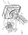
- an integrated apparatus 10 includes a respiratory monitor system 12 and a CT imaging device 14 .
- the integrated apparatus 10 is particularly well suited for planning and executing minimally invasive surgical procedures for in-vivo placement of instruments and/or objects within a patient during one or more breath holds.
- the respiratory monitor system 12 includes a respiratory sensor 20 preferably formed as a belt 22 adapted for attachment around the abdomen or chest of a patient.
- the respiratory sensor 20 includes an air bellows sensor and pressure transducer (not shown) for generating a signal corresponding to the displacement of a patient's abdomen during respiration.
- the respiratory sensor 20 is attached to the imaging device 14 at a suitable electronic connection point 24 .
- the preferred imaging device 14 is a volumetric diagnostic CT imaging apparatus 30 as shown.
- the CT imaging apparatus 30 is disposed in axial alignment with a patient table 32 and support 33 such that a patient or subject on the support surface can be moved into and through a bore 34 of the CT volumetric imager 30 .
- the CT scanner includes an x-ray tube mounted for rotation about a preselected plane.
- the x-ray tube projects a fan shaped beam of radiation through a ring 36 of radiation translucent material, through the patient support 33 , through a region of interest of the patient, and to a ring or arc of radiation detectors disposed opposite the x-ray tube.
- a series of data lines are generated, which data lines are reconstructed into at least a slice image using well known techniques by a reconstruction processor included in a control console 40 operatively connected with the CT imager 30 .
- the patient support 33 moves longitudinally as the x-ray tube is rotating around the subject such that a selected volume of the patient is scanned along a spiral path or a series of slices.
- the position of the x-ray tube is monitored by a rotational position encoder and the longitudinal position of the patient support is monitored by similar position encoders disposed within the table 32 .
- the reconstruction processor reconstructs a volumetric image representation from the generated data lines.
- the control console 40 includes one or more human readable display devices preferably in the form of an operator monitor 42 and at least one operator input device 44 , such as a keyboard, track ball, mouse, or the like.
- a human readable patient display device 50 is supported from overhead on a track or by other means atop the CT scanner 30 .
- the patient display device can be oriented or moved into selected positions for ready viewing by a patient on the support 33 .
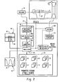
- FIGURE 2 is a schematic representation of the subject CT integrated respiratory monitoring apparatus 10 .
- a processing computer system 60 is operatively connected with each of the components of the subject integrated apparatus 10 . More particularly, the computer system 60 is adapted to generate a patient image volume data set 43 , an operator's image 46 of a patient breath hold signal on the operator monitor 42 as well as a patient breathing image 52 on the patient display device 50 .
- the preferred patient breathing image 52 is visual indicia in the form of a bar graph 54 having a height representative of an inhalation level of the patient on a scale of percentage of vital capacity (%VC).
- %VC percentage of vital capacity
- the patient breathing image 52 is in the form of a bar graph 54 to make it easy for patients to relate and coordinate the image with their own physical breathing conditions and breath hold levels.
- a bar graph is illustrated, other forms of patient breathing images can be used as well such as, for example, a graduated cylinder, a progress bar, an animated diaphragm, and the like.
- the patient uses the graphic feedback to set and maintain a breath hold. With such a display, a few moments of training prior to the CT scan enables a high percentage of patients to control their breathing in order to accomplish desired breath hold maneuvers.
- the computer system 60 is also operatively connected with the respiratory sensor 20 at the electronic connection point 24 .
- the respiratory sensor 20 includes a belt 22 adapted to be worn across the abdomen or rib cage of a patient as discussed above and an air bellows device 26 as well as a respiratory sensor circuit 28 .
- the respiratory sensor circuit 28 includes a pressure transducer 28a responsive to a condition of the air bellows 26 as well as an amplification circuit 28b for amplifying the electrical signal from the pressure sensor to a level suitable for input to an analog to digital converter circuit 28c .
- the conversion of analog signals from the belt 22 representative of a position of the patient's abdomen to a digital signal for use by the computer system 60 is well known in the art and can be accomplished using any suitable equivalent means.
- the computer system 60 includes a processor 62 for executing instructions to control the integrated apparatus 10 in accordance with the present invention.
- the computer system 60 further includes a memory storage device 64 adapted to store various data and parameters for operating the integrated apparatus 10 including a portion of memory dedicated to storing a plurality of sets of patient volumetric image data 66 in association with patient breath hold level data 68 .
- the subject apparatus 10 stores each volumetric patient image data set obtained during a scan together with the patient breath hold level data obtained during the scan in a paired relationship.
- the breath hold level data can be stored together with the volumetric image data in a designated field or segregated portion of the image data as desired.
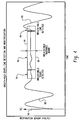
- FIGURE 3 shows a representative operator's image 46 displayed on the operator monitor 42 of the control console 40 .
- the image 46 includes a patient breathing signal or graph 80 shown on a Cartesian coordinate system with time plotted on the abscissa and the patient breathing level signal in volts plotted on the ordinate.
- the breathing signal 80 is derived from the respiratory sensor 20 of the respiratory monitor system 12 and through the computer system 60 described above.
- a patient target breath hold level 82 is selectable using a target slider button 84 or by selecting preset configuration parameters such as target +/-5% or target +/10%, or the like.
- a breath hold range is set between an upper breath hold level 86 using target slider 88 and a lower breath hold level 90 using target slider 92 .
- the target sliders can be used to determine the low and high extents of the patient's vital capacity (VC).
- the patient's normal breathing is outside of the upper and lower breath hold levels 86, 90 , respectively. More particularly, as illustrated by way of example, the breath hold tolerance range is about 1/4 of the patient's vital capacity (VC) and the nominal target breath hold level 82 is at about 80% of the patient's vital capacity.
- the subject integrated apparatus 10 detects a breath hold start based on the breathing signal 80 being within the breath hold tolerance range 86, 90 .
- the breath hold sustained is detected during a second time period 96 set by the operator and stored as the breath sustain period data 72 discussed above.
- a breath hold end is detected when the breathing graph 80 exceeds the upper breath hold level 86 .
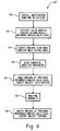
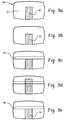
- FIGURES 5 , 6a-6c, and 7a-7c will be used to describe a method 100 for acquiring patient images obtained at target breath hold levels in accordance with a preferred embodiment of the present invention.
- the respiratory sensor 20 is installed 102 by connecting the belt 22 to the patient's abdomen.
- the interventionist observes patient's breathing levels ( Fig. 6a ) on the operator's monitor 42 in order to determine a patient's vital breathing capacity.
- a patient breathing image 52 is also displayed ( Fig. 7a ) but in the form of a bar graph 54 on the patient display device 50 .
- the interventionist sets a breath hold target level 82 and upper and lower breath hold levels 86, 90 in a manner described above using the control buttons 84, 86, 92 illustrated in FIGURE 3 .
- the target breath hold range 99 is illustrated on the operator's image 46 as a rectangular box having a height corresponding to the range.
- the breath hold range 99 is illustrated on the patient breathing image 52 as a horizontal bar having a width defined by boundaries 86,90 corresponding to the target breath hold range 86, 90 .
- the interventionist instructs the patient to target a breath hold condition such that the top edge of the bar graph 54 is positioned within the horizontal bar 99 defining the breath hold tolerance range.
- the intuitive nature of the bar graph representation of breathing level makes it easy for a patient to maneuver his/her breath hold condition into the target range.
- the computer system 60 of the subject integrated apparatus 10 detects a breath hold condition when the patient's breathing level is within the selected range using the range/level parameter 74 and duration 72 parameters selected by the operator.
- a scan ready signal is generated at step 112 based upon the detected breath hold.
- the operator's display shows the patient's breathing graph 80 together with the range target rectangle 99 .
- the patient display of FIGURE 7b shows the bar graph 54 overlaid on the target range 99 .
- the system determines whether the breathing graph 80 either exceeded the upper breath hold level 86 or fell short of the lower breath hold level 99 during the scan. If at any point during the scan the breathing graph 80 fell outside of the defined upper and lower breath hold level boundaries, the operator is alerted at step 116 so that suitable corrective action can be taken such as, for example discarding the obtained image data, reestablishing the target breath hold level and providing a subsequent patient scan.
- the volumetric patient image data generated during the scan is stored in the memory storage device 60 in association with the patient breath hold information including breath hold level data 68 breath hold sustain data 70 breath hold period data 72 , and breath hold level/range data 74 .
- breath hold level data particularly breath hold level (% VC) data together with the volumetric patient image data
- % VC breath hold level
- the storage of the patient breath hold level data, particularly breath hold level (% VC) data together with the volumetric patient image data is particularly useful for comparison type evaluations such as, for example, in emphysema evaluations where the period between scans can be weeks or months. In those cases, it is critical that the comparison between patient image scans be made at equivalent breath hold datums.
- the ability to store patient breath hold level data together with the volumetric patient image data is significant for providing pre-operative and intra-operative breath hold congruency as described below.
- the respiratory sensor 20 is connected with the patient by attaching the belt to the abdomen or across the chest.
- the patient's respiratory function is illustrated as a moving bar graph 54 in the patient breathing image 52 on the patient display device 50 ( Fig. 9a ).
- step 152 the patient holds his breath at a selected level. This is illustrated in the bar graph 54 in FIGURE 9b .
- the patient breathing image 52 is provided with a range indicia 99 .
- the imaging device 14 is initiated to start a scan while the patient holds his breath at a physical level in order to maintain the bar graph 54 in the range 99 .
- the operator instructs the patient to breathe normally at which time the color of the bar graph 54 in the patient breathing image 52 changes color as the bar graph moves above and below the range 99 ( Fig. 9d ).
- the changing color provides visual indicia of an out of range breath hold condition which is easily recognizable and intuitive to the patient. Thereafter, the patient and the doctor together monitor normal breathing of the patient.
- step 158 the patient is instructed to sustain the breath hold level used during the patient scanning in step 154 .
- the patient controls the breathing maneuver in order to cause the top end of the bar graph 54 to lie within the range 99 illustrated on the patient breathing image 52 .
- the patient holds his breath in this manner during which time a needle or other object can be inserted into the patient using standard image guided techniques based on the volumetric patient image data using well known techniques.
- step 160 the patient is allowed to breathe normally so that needle position in the patient can be verified such as by a subsequent scan of the patient using the CT scanner or other device/modality ( Fig. 9d ).
- step 162 the patient is instructed to once again match the breath hold level within the selected range so that the needle can be advanced further into the patient or so that other procedures or steps can be taken at the target patient breath hold level ( Fig. 9c ).
- the subject CT integrated respiratory device is also particularly useful in respiratory gating of the scanning function. This involves triggering the CT scanner 14 at selected points in the respiratory cycle while the patient is freely breathing.
- Clinical applications for respiratory gating include procedures that have a duration or image acquisition period that exceeds the amount of time that a patient can be expected to hold their breath.
- One example of such application is for imaging a patient for a liver perfusion procedure.
- the subject respiratory tracking and monitoring device is self-calibrating relative to an estimated value proportional to a patient's vital capacity and allows CT slices to be triggered at optimal points in the patient breathing cycle.
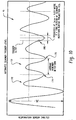
- a patient breathing graph 80 is displayed as an operator's image 46 on an operator monitor 42 .
- an embodiment of the invention provides an integrated trigger function to acquire a complete scan based on scanning only at specific points in the respiratory cycle.
- the scanner is triggered at selected phases of the respiratory cycle during free breathing.
- the triggering function adapts to the scanner's image acquisition capabilities. In this description, it is assumed that the scanner requires T seconds to acquire a projection for a slice. T is related to scan speed which decreases with improvements in scanner technology and scan projection angle.
- Respiratory motion artifacts are minimized by triggering the scan/slice at the minimum in the respiratory cycle.
- the signal processing further minimizes motion effects by centering the projection acquisition time interval, T, at a time point estimated for the minimum in the respiratory signal.
- the slice is triggered at T/2 from the anticipated minimum in the respiratory cycle.
- triggering based on patient breathing a fixed percentage of vital capacity is provided.
- the respiratory signal non-breath hold
- the invention can be used at any selected point in the respiratory cycle.
- the image slice is triggered in the imaging device 14 by a gating circuit 182 of the computer system 60 at a start point 180 so that about half of the image data is acquired on a patient exhale before a minimum lower breath level and the remaining portion of the image data is acquired on a patient inhale after the minimum lower breath level.
- the present system is useful for automatic scanner triggering at any point in the respiratory cycle based upon patient free breathing graph signals inputted into a gating or trigger circuit.
- some procedures may require imaging at a maximum point in the breathing cycle and others in the middle range of the cycle.
- a sensing device 200 is attached on a first end 202 to the patient support 33 of the patient table 32 .
- the device is preferably telescopic and includes a distal end 204 adapted to contact the abdomen of the patient disposed on the patient support.
- a shaft encoded rotational joint 206 is provided between the distal end 202 of the device and the patient support so that the position of the distal end can be accurately determined relative to the first end. In that way, motion of the patient is measured on a relative basis during the patient respiratory cycle. More particularly, as the patient breathes, the respiratory sensor 20 rotates in a direction A noted in the FIGURE.
- the shaft encoded rotational joint is a high resolution optical encoder such as one providing 9600 ticks or counts per rotation to resolve the respiratory motion of the patient.
Landscapes
- Health & Medical Sciences (AREA)
- Life Sciences & Earth Sciences (AREA)
- Medical Informatics (AREA)
- Engineering & Computer Science (AREA)
- Molecular Biology (AREA)
- Surgery (AREA)
- Biophysics (AREA)
- Pathology (AREA)
- Veterinary Medicine (AREA)
- Biomedical Technology (AREA)
- Heart & Thoracic Surgery (AREA)
- Public Health (AREA)
- Physiology (AREA)
- Physics & Mathematics (AREA)
- Animal Behavior & Ethology (AREA)
- General Health & Medical Sciences (AREA)
- Dentistry (AREA)
- Oral & Maxillofacial Surgery (AREA)
- High Energy & Nuclear Physics (AREA)
- Nuclear Medicine, Radiotherapy & Molecular Imaging (AREA)
- Optics & Photonics (AREA)
- Radiology & Medical Imaging (AREA)
- Apparatus For Radiation Diagnosis (AREA)
- Measurement Of The Respiration, Hearing Ability, Form, And Blood Characteristics Of Living Organisms (AREA)
Claims (21)
- Integriertes Gerät (10) mit Atemüberwachungsvorrichtung (12) und Bildgebungsvorrichtung (14), das Folgendes umfasst:Atemerfassungsmittel (20), das vorgesehen ist, um mit einem Patienten verbunden zu werden und ein Atemsignal zu erzeugen, das einen Atemanhaltepegel des Patienten während eines Anhalten des Atmens darstellt; undBildgebungsmittel (14), das vorgesehen ist, um den Patienten während des genannten Anhalten des Atmens abzutasten und einen Volumenbilddatensatz (43) des Patienten zu erzeugen, wobei das Atemerfassungsmittel (20) und das Bildgebungsmittel (14) betriebsfähig verbunden sind, um das genannte Atemsignal, das den Atemanhaltepegel des Patienten darstellt, dem genannten Volumenbilddatensatz des Patienten zuzuordnen, undeine Schaltung zum Ermitteln des Atemanhaltens (63), die das genannte Atemsignal empfängt und ein Atemanhalte-Verriegelungssignal erzeugt, wenn ein Pegel des genannten Atemsignals während einer vorgegebenen Zeitspanne innerhalb eines vorgegebenen Bereichs liegt, und wobei die genannte Schaltung zum Ermitteln des Atemanhaltens (63) vorgesehen ist, um ein Atemanhalte-Dauersignal nach der genannten vorgegebenen Zeitspanne zu erzeugen, das angibt, dass das genannte Atemsignal während der genannten vorgegebenen Zeitspanne innerhalb des genannten vorgegebenen Bereichs geblieben ist, wobei das Atemanhalte-Dauersignal in dem genannten Gerät (10) dem genannten Volumenbilddatensatz (43) des Patienten zugeordnet ist, undeinen Parameterspeicher (64), wobei der genannte vorgegebene Bereich durch einen Bediener des integriertes Geräts basierend auf einem Prozentsatz der Vitalkapazitätswerte des Patienten auswählbar ist, der in dem genannten Parameterspeicher des Geräts eingestellt wurde; und wobei die genannte vorgegebene Zeitspanne durch den Bediener des integrierten Geräts auswählbar ist, indem Zeitwerte in dem genannten Parameterspeicher eingestellt werden.
- Integriertes Gerät (10) nach Anspruch 1, weiterhin mit einer von Menschen lesbaren Patientenanzeigevorrichtung (50), die durch den Patienten beobachtet werden kann, um visuelle Zeichen (54, 80) des genannten Atemanhaltepegels anzuzeigen.
- Integriertes Gerät (10) nach Anspruch 2, wobei die genannten visuellen Zeichen (54, 80) eine animierte Darstellung einer physiologischen Struktur des genannten Patienten sind.
- Integriertes Gerät (10) nach Anspruch 2, wobei es sich bei den genannten visuellen Zeichen um ein Balkendiagramm (54) handelt.
- Integriertes Gerät (10) nach Anspruch 1, weiterhin mit einer Datenspeichervorrichtung (64) zum Speichern des genannten Volumenbilddatensatzes (43) und der dem Volumenbilddatensatz zugeordneten, das Atemsignal darstellenden Daten (68-74).
- Integriertes Gerät (10) nach Anspruch 1, weiterhin mit einer von Menschen lesbaren Bedieneranzeigevorrichtung (42), die durch einen Bediener des genannten integrierten Geräts beobachtet werden kann, um visuelle Zeichen des genannten Atemsignals während des genannten Atemanhaltens zusammen mit einem anhand des genannten Volumenbilddatensatzes entwickelten Bild des Patienten basierend auf dem genannten Volumenbilddatensatz anzuzeigen.
- Integriertes Gerät (10) nach Anspruch 6, wobei es sich bei den visuellen Zeichen um eine graphische Anzeige (80) des genannten Atemsignals auf der genannten Bedieneranzeigevorrichtung handelt.
- Integriertes Gerät (10) nach Anspruch 1, wobei der genannte vorgegebene Bereich 5% Vitalkapazität VC des genannten Patienten beträgt und die genannte vorgegebene Zeitspanne 2 bis 4 Sekunden beträgt.
- Integriertes Gerät (10) nach Anspruch 1, das weiterhin Folgendes umfasst:eine Gating-Schaltung (182), die betriebsfähig mit dem genannten Bildgebungsmittel (14) verbunden ist und auf das genannte Atemanhalte-Verriegelungssignal reagiert, um den genannten Scan des genannten Patienten einzuleiten.
- Integriertes Gerät (10) nach Anspruch 9, wobei
das Gerät (10) einen ersten Eingang (SCAN) zur Verwendung durch einen Bediener des Geräts umfasst, um selektiv die Einleitung eines Scans des Patienten anzufordern; und
die Gating-Schaltung (182) auf den genannten ersten Eingang reagiert, um den genannten Scan nur bei Vorliegen des genannten Atemanhalte-Verriegelungssignals einzuleiten. - Integriertes Gerät (10) nach Anspruch 1, das weiterhin eine visuelle Atemanhalte-Verrieglungsanzeige umfasst, um einem Bediener des Geräts visuelle Zeichen zu liefern, dass der Patient das Atemanhalten für die genannte vorgegebene Zeitspanne auf einem Niveau innerhalb des vorgegebenen Bereichs durchgehalten hat.
- Integriertes Gerät (10) nach Anspruch 1, wobei:die genannte Schaltung zum Ermitteln des Atemanhaltens (63) vorgesehen ist, um den Logikpegel des genannte Atemanhalte-Verriegelungssignals zu ändern, wenn ein Pegel des genannten Atemsignals außerhalb des genannten vorgegebenen Bereichs liegt; unddas genannte Bildgebungsmittel (14) vorgesehen ist, um den genannten Scan des Patienten in Reaktion auf die genannte Änderung des Logikpegels des genannten Atemanhalte-Verriegelungssignals zu unterbrechen.
- Integriertes Gerät (10) nach Anspruch 12, wobei das genannte Bildgebungsmittel (14) vorgesehen ist, um den genannten Scan des Patienten in Reaktion auf eine weitere Änderung des Logikpegels des genannten Atemanhalte-Verriegelungssignals fortzusetzen.
- Integriertes Gerät (10) nach Anspruch 1, wobei:die genannte Schaltung zum Ermitteln des Atemanhaltens (63) vorgesehen ist, um den Logikpegel des genannte Atemanhalte-Verriegelungssignals zu ändern, wenn ein Pegel des genannten Atemsignals außerhalb des genannten vorgegebenen Bereichs liegt; unddas genannte Bildgebungsmittel (14) vorgesehen ist, um Zeichen der genannten Änderung des Logikpegels des genannten Atemanhalte-Verriegelungssignals dem genannten Volumenbilddatensatz des Patienten zuzuordnen.
- Integriertes Gerät (10) nach Anspruch 1, wobei das Atemerfassungsmittel (20) einen Gurt (22) umfasst, der um den Bauch oder den Brustkorb des Patienten getragen wird, wobei der Gurt das genannte Atemsignal in Reaktion auf die Bewegung des genannten Patienten während das Atmens erzeugt.
- Integriertes Gerät (10) nach Anspruch 1, wobei das Atemerfassungsmittel (20) ein Sondenelement (200) umfasst, das an einem ersten Ende (204) vorgesehen ist, um Kontakt mit dem Bauch oder der Brust des Patienten herzustellen, und an einem zweiten Ende (202) vorgesehen ist, um betriebsfähig mit dem genannten Bildgebungsmittel (14) verbunden zu werden, wobei das Sondenelement (200) das genannte Atemsignal in Reaktion auf die Bewegung des genannten Patienten relativ zu dem genannten Bildgebungsmittel (14) während des Atmens erzeugt.
- Integriertes Gerät (10) nach Anspruch 1, das vorgesehen ist, um präoperative und intraoperative Atemhaltekongruenz bei den Patienten herzustellen, wobei:der Atemsensor (20) vorgesehen ist, um ein erstes Atemsignal, das einen präoperativen Atemanhaltepegel des Patienten während eines präoperativen Atemanhaltens darstellt, und ein zweites Atemsignal, das einen intraoperativen Atemanhaltepegel des Patienten während eines intraoperativen Atemanhaltens darstellt, zu erzeugen;die Bildgebungsvorrichtung (14) vorgesehen ist, um einen präoperativen Volumenbilddatensatz (43) des Patienten zu erzeugen, wobei der Atemsensor (20) und die Bildgebungsvorrichtung (14) betriebsfähig verbunden sind, um das genannte erste Atemsignal, das den präoperativen Atemanhaltepegel des Patienten darstellt, dem genannten präoperativen Volumenbilddatensatz (43) des Patienten zuzuordnen, wobei das Gerät weiterhin Folgendes umfasst:eine Datenspeichervorrichtung (60) zum Speichern erster, dem präoperativen Volumenbilddatensatz zugeordneter, das Atemsignal darstellender Daten, wobei die Datenspeichervorrichtung den Parameterspeicher umfasst; undeine von Menschen lesbare Anzeigevorrichtung (50), die durch den Patienten beobachtet werden kann, um erste visuelle Zeichen (99) des genannten präoperativen Atemanhaltepegels basierend auf den genannten ersten Daten aus der genannten Datenspeichervorrichtung zusammen mit zweiten visuellen Zeichen (54) des genannten intraoperativen Atemanhaltepegels, der durch den genannten Atemsensor erzeugt wurde, anzuzeigen.
- Integriertes Gerät (10) nach Anspruch 17, wobei die genannte von Menschen lesbare Patientenanzeigevorrichtung (50) die genannten ersten sichtbaren Zeichen (99) auf eine nicht-bewegliche Weise als ein Ziel für den genannten Patienten anzeigt und die genannten zweiten visuellen Zeichen (54) als ein bewegliches Bild anzeigt, das den genannten intraoperativen Atemanhaltepegel des Patienten darstellt.
- Abtastverfahren während eines Atemanhaltens eines Patienten, das Folgendes umfasst:Erzeugen eines Atemsignals mithilfe eines Atemerfassungsmittels (20), das vorgesehen ist, um mit einem Patienten verbunden zu werden, wobei das Atemsignal einen Atemanhaltepegel eines Patienten während eines Anhalten des Atmens darstellt; undAbtasten des Patienten mithilfe einer Bildgebungsvorrichtung (14) während des genannten Anhalten des Atmens und Erzeugen eines Volumenbilddatensatzes (43) des Patienten, wobei das Atemerfassungsmittel (20) und die Bildgebungsvorrichtung (14) betriebsfähig verbunden sind, um das genannte Atemsignal, das den Atemanhaltepegel des Patienten darstellt, dem genannten Volumenbilddatensatz des Patienten zuzuordnen;Empfangen eines vorgegebenen Bereichs, der durch einen Bediener des integrierten Geräts auf der Basis eines Prozentsatzes der in einem Parameterspeicher des Geräts eingestellten Vitalkapazitätswerte des Patienten ausgewählt werden kann; und wobei eine vorgegebene Zeitspanne durch den Bediener des integrierten Geräts auswählbar ist, indem Zeitwerte in dem genannten Parameterspeicher eingestellt werden;Empfangen des genannten Atemsignals und Erzeugen eines Atemanhalte-Verriegelungssignals durch eine Schaltung zum Ermitteln des Atemanhaltens (63), wenn ein Pegel des genannten Atemsignals während einer vorgegebenen Zeitspanne innerhalb eines vorgegebenen Bereichs liegt, und Erzeugen eines Atemanhalte-Dauersignals durch die genannte Schaltung zum Ermitteln des Atemanhaltens (63) nach der genannten vorgegebenen Zeitspanne, das angibt, dass das genannte Atemsignal während der genannten vorgegebenen Zeitspanne innerhalb des genannten vorgegebenen Bereichs geblieben ist, wobei das Atemanhalte-Dauersignal in dem genannten Gerät (10) dem genannten Volumenbilddatensatz (43) des Patienten zugeordnet ist.
- Verfahren nach Anspruch 19, das weiterhin Folgendes umfasst:Schaffen einer Gating-Schaltung, die betriebsfähig mit der genannten Bildgebungsvorrichtung (14) verbunden ist und auf das genannte Atemanhalte-Verriegelungssignal reagiert, um den genannten Scan des genannten Patienten einzuleiten;Schaffen eines ersten Eingangs (SCAN) zur Verwendung durch einen Bediener des Geräts, um selektiv die Einleitung eines Scans des Patienten anzufordern; undwobei die Gating-Schaltung auf den genannten ersten Eingang reagiert, um den genannten Scan nur bei Vorliegen des genannten Atemanhalte-Verriegelungssignals einzuleiten.
- Verfahren nach Anspruch 19, das weiterhin Folgendes umfasst:Ändern des Logikpegels des genannten Atemanhalte-Verriegelungssignals, wenn ein Pegel des genannten Atemsignals außerhalb des genannten vorgegebenen Bereichs liegt; undUnterbrechen des genannten Scans des Patienten in Reaktion auf die genannte Änderung des Logikpegels des genannten Atemanhalte-Verriegelungssignals.
Applications Claiming Priority (5)
| Application Number | Priority Date | Filing Date | Title |
|---|---|---|---|
| US280626 | 1981-07-06 | ||
| US36948502P | 2002-04-03 | 2002-04-03 | |
| US369485P | 2002-04-03 | ||
| US10/280,626 US7182083B2 (en) | 2002-04-03 | 2002-10-25 | CT integrated respiratory monitor |
| PCT/US2003/008159 WO2003084405A2 (en) | 2002-04-03 | 2003-03-17 | Ct integrated respiratory monitor |
Publications (2)
| Publication Number | Publication Date |
|---|---|
| EP1499239A2 EP1499239A2 (de) | 2005-01-26 |
| EP1499239B1 true EP1499239B1 (de) | 2012-07-18 |
Family
ID=28678079
Family Applications (1)
| Application Number | Title | Priority Date | Filing Date |
|---|---|---|---|
| EP03716647A Expired - Lifetime EP1499239B1 (de) | 2002-04-03 | 2003-03-17 | Ct-integriertes atemüberwachungsgerät |
Country Status (5)
| Country | Link |
|---|---|
| US (1) | US7182083B2 (de) |
| EP (1) | EP1499239B1 (de) |
| JP (1) | JP2005521507A (de) |
| AU (1) | AU2003220348A1 (de) |
| WO (1) | WO2003084405A2 (de) |
Cited By (1)
| Publication number | Priority date | Publication date | Assignee | Title |
|---|---|---|---|---|
| DE102018217888A1 (de) * | 2018-10-18 | 2020-04-23 | Siemens Healthcare Gmbh | Durchführen einer bildgebenden Messung eines Patienten in einem Computertomographiesystem |
Families Citing this family (111)
| Publication number | Priority date | Publication date | Assignee | Title |
|---|---|---|---|---|
| US5915379A (en) | 1997-03-14 | 1999-06-29 | Nellcor Puritan Bennett Incorporated | Graphic user interface for a patient ventilator |
| US7158610B2 (en) * | 2003-09-05 | 2007-01-02 | Varian Medical Systems Technologies, Inc. | Systems and methods for processing x-ray images |
| US8788020B2 (en) | 1998-10-23 | 2014-07-22 | Varian Medical Systems, Inc. | Method and system for radiation application |
| US6937696B1 (en) * | 1998-10-23 | 2005-08-30 | Varian Medical Systems Technologies, Inc. | Method and system for predictive physiological gating |
| US7769430B2 (en) * | 2001-06-26 | 2010-08-03 | Varian Medical Systems, Inc. | Patient visual instruction techniques for synchronizing breathing with a medical procedure |
| US7182083B2 (en) * | 2002-04-03 | 2007-02-27 | Koninklijke Philips Electronics N.V. | CT integrated respiratory monitor |
| EP1505905A4 (de) * | 2002-05-17 | 2006-01-25 | Henry M Jackson Foundation | Atmungsbezogene bilddarstellung |
| US7869859B2 (en) * | 2003-03-10 | 2011-01-11 | Kabushiki Kaisha Toshiba | X-ray CT apparatus having a display to display information inputted from a remote operator console |
| US8571639B2 (en) | 2003-09-05 | 2013-10-29 | Varian Medical Systems, Inc. | Systems and methods for gating medical procedures |
| US7367953B2 (en) * | 2003-11-26 | 2008-05-06 | Ge Medical Systems Global Technology Company | Method and system for determining a period of interest using multiple inputs |
| US8285359B2 (en) * | 2003-11-26 | 2012-10-09 | General Electric Company | Method and system for retrospective gating using multiple inputs |
| US8064983B2 (en) * | 2003-11-26 | 2011-11-22 | General Electric Company | Method and system for prospective gating using multiple inputs |
| US20050113673A1 (en) * | 2003-11-26 | 2005-05-26 | Avinash Gobal B. | Method and system to reduce motion-related image artifacts during breath holding |
| US7756565B2 (en) * | 2003-11-26 | 2010-07-13 | General Electric Company | Method and system for composite gating using multiple inputs |
| US7844317B2 (en) * | 2003-11-26 | 2010-11-30 | General Electric Company | Method and system for estimating three-dimensional respiratory motion |
| JP4467987B2 (ja) * | 2004-01-05 | 2010-05-26 | 株式会社東芝 | 核医学診断装置 |
| US8055045B2 (en) * | 2004-03-19 | 2011-11-08 | Hitachi Medical Corporation | Method and system for collecting image data from image data collection range including periodically moving part |
| JP4571429B2 (ja) * | 2004-04-02 | 2010-10-27 | ジーイー・メディカル・システムズ・グローバル・テクノロジー・カンパニー・エルエルシー | Ct断層像の生成方法及びその装置 |
| US8457717B2 (en) * | 2004-04-08 | 2013-06-04 | Stanford University | Method and system of adaptive control for reducing motion artifacts and patient dose in four dimensional computed tomography |
| US7868884B2 (en) * | 2004-08-31 | 2011-01-11 | General Electric Company | System and method for generating a digital image of an internal anatomy of a person |
| US20060074305A1 (en) * | 2004-09-30 | 2006-04-06 | Varian Medical Systems Technologies, Inc. | Patient multimedia display |
| CA2599932C (en) | 2005-03-04 | 2015-11-24 | Visualsonics Inc. | Method for synchronization of breathing signal with the capture of ultrasound data |
| US7266174B2 (en) * | 2005-03-07 | 2007-09-04 | General Electric Company | Radiographic inspection of airframes and other large objects |
| EP1863377A4 (de) * | 2005-04-01 | 2010-11-24 | Visualsonics Inc | System und verfahren zur 3-d-visualisierung von gefässstrukturen mit ultraschall |
| JP4350679B2 (ja) | 2005-05-26 | 2009-10-21 | ジーイー・メディカル・システムズ・グローバル・テクノロジー・カンパニー・エルエルシー | 磁気共鳴イメージング装置および画像撮影装置 |
| US9119541B2 (en) * | 2005-08-30 | 2015-09-01 | Varian Medical Systems, Inc. | Eyewear for patient prompting |
| WO2007046220A1 (ja) * | 2005-10-18 | 2007-04-26 | Konica Minolta Medical & Graphic, Inc. | X線撮影装置 |
| US7678063B2 (en) * | 2006-01-06 | 2010-03-16 | Mayo Foundation For Medical Education And Research | Motion monitor system for use with imaging systems |
| DE602006006897D1 (de) * | 2006-03-31 | 2009-07-02 | Sony Deutschland Gmbh | System zum Nachweis eines Lecks in einer Batterie |
| US7443946B2 (en) * | 2006-04-10 | 2008-10-28 | General Electric Company | Methods and apparatus for 4DCT imaging systems |
| US8021310B2 (en) | 2006-04-21 | 2011-09-20 | Nellcor Puritan Bennett Llc | Work of breathing display for a ventilation system |
| JP2007301153A (ja) * | 2006-05-11 | 2007-11-22 | Ge Medical Systems Global Technology Co Llc | 医用画像撮影装置 |
| DE102006040943B4 (de) * | 2006-08-31 | 2016-12-22 | Siemens Healthcare Gmbh | Verfahren zum Bereitstellen eines 3D-Röntgenbilddatensatzes und Röntgenbildgebungssystem |
| JP4989166B2 (ja) * | 2006-09-14 | 2012-08-01 | ジーイー・メディカル・システムズ・グローバル・テクノロジー・カンパニー・エルエルシー | 画像診断装置 |
| US7784461B2 (en) | 2006-09-26 | 2010-08-31 | Nellcor Puritan Bennett Llc | Three-dimensional waveform display for a breathing assistance system |
| EP2068711B1 (de) * | 2006-10-06 | 2014-01-15 | Elekta AB (publ) | Atemsensor |
| CN101161203B (zh) * | 2006-10-11 | 2011-01-26 | 株式会社东芝 | X射线计算机断层及医用图像摄影装置、呼吸指示装置 |
| US8401620B2 (en) * | 2006-10-16 | 2013-03-19 | Perfint Healthcare Private Limited | Needle positioning apparatus and method |
| US20080130972A1 (en) * | 2006-11-30 | 2008-06-05 | General Electric Company | Storing imaging parameters |
| JP4896763B2 (ja) * | 2007-02-19 | 2012-03-14 | 株式会社東芝 | 呼吸抑制部材および磁気共鳴映像装置 |
| US20080243018A1 (en) * | 2007-03-30 | 2008-10-02 | General Electric Company | System and method to track a respiratory cycle of a subject |
| DE102007017269A1 (de) * | 2007-04-12 | 2008-10-16 | Siemens Ag | Bildakquisitionssystem und -verfahren zur Durchführung von CT- bwz. MRT-gesteuerten Interventionen in Korrelation mit der Atemlage eines Patienten |
| WO2009142545A2 (en) * | 2008-05-22 | 2009-11-26 | Vladimir Yegorovich Balakin | Charged particle cancer therapy patient positioning method and apparatus |
| CA2725315C (en) * | 2008-05-22 | 2015-06-30 | Vladimir Yegorovich Balakin | X-ray method and apparatus used in conjunction with a charged particle cancer therapy system |
| US9058910B2 (en) | 2008-05-22 | 2015-06-16 | Vladimir Yegorovich Balakin | Charged particle beam acceleration method and apparatus as part of a charged particle cancer therapy system |
| US8896239B2 (en) | 2008-05-22 | 2014-11-25 | Vladimir Yegorovich Balakin | Charged particle beam injection method and apparatus used in conjunction with a charged particle cancer therapy system |
| CN102119586B (zh) | 2008-05-22 | 2015-09-02 | 弗拉迪米尔·叶戈罗维奇·巴拉金 | 多场带电粒子癌症治疗方法和装置 |
| WO2009142544A2 (en) | 2008-05-22 | 2009-11-26 | Vladimir Yegorovich Balakin | Charged particle cancer therapy beam path control method and apparatus |
| EP2283713B1 (de) | 2008-05-22 | 2018-03-28 | Vladimir Yegorovich Balakin | Vorrichtung zur krebstherapie mit geladenen teilchen mit mehreren achsen |
| WO2009142550A2 (en) | 2008-05-22 | 2009-11-26 | Vladimir Yegorovich Balakin | Charged particle beam extraction method and apparatus used in conjunction with a charged particle cancer therapy system |
| US10667727B2 (en) | 2008-09-05 | 2020-06-02 | Varian Medical Systems, Inc. | Systems and methods for determining a state of a patient |
| SG173879A1 (en) | 2009-03-04 | 2011-10-28 | Protom Aozt | Multi-field charged particle cancer therapy method and apparatus |
| DE102009035250B4 (de) * | 2009-07-29 | 2019-06-13 | Meierhofer Medizintechnik Gmbh | Verfahren und System zur Überwachung des medizinischen Zustandes eines Patienten |
| US9119925B2 (en) | 2009-12-04 | 2015-09-01 | Covidien Lp | Quick initiation of respiratory support via a ventilator user interface |
| US8924878B2 (en) | 2009-12-04 | 2014-12-30 | Covidien Lp | Display and access to settings on a ventilator graphical user interface |
| US8335992B2 (en) * | 2009-12-04 | 2012-12-18 | Nellcor Puritan Bennett Llc | Visual indication of settings changes on a ventilator graphical user interface |
| US8499252B2 (en) | 2009-12-18 | 2013-07-30 | Covidien Lp | Display of respiratory data graphs on a ventilator graphical user interface |
| US9262588B2 (en) | 2009-12-18 | 2016-02-16 | Covidien Lp | Display of respiratory data graphs on a ventilator graphical user interface |
| RU2612859C2 (ru) | 2010-10-14 | 2017-03-13 | Конинклейке Филипс Электроникс Н.В. | Сбор магнитно-резонансных данных с использованием наблюдения физиологического состояния |
| US20120190970A1 (en) | 2010-11-10 | 2012-07-26 | Gnanasekar Velusamy | Apparatus and method for stabilizing a needle |
| EP2681711B1 (de) * | 2011-03-02 | 2016-06-29 | Koninklijke Philips N.V. | Visualisierung für eine navigationsführung |
| US9271692B2 (en) * | 2011-04-01 | 2016-03-01 | Varian Medical Systems, Inc. | System and method for triggering an imaging process based on non-periodicity in breathing |
| US9392962B2 (en) | 2011-04-01 | 2016-07-19 | Varian Medical Systems, Inc. | Prediction of breathing signal and determining non-periodicity of breathing using signal-phase histogram |
| US9047701B2 (en) * | 2012-03-31 | 2015-06-02 | Varian Medical Systems, Inc. | 4D cone beam CT using deformable registration |
| US20130338525A1 (en) * | 2012-04-24 | 2013-12-19 | Irobot Corporation | Mobile Human Interface Robot |
| US11857149B2 (en) * | 2012-06-21 | 2024-01-02 | Globus Medical, Inc. | Surgical robotic systems with target trajectory deviation monitoring and related methods |
| US11253327B2 (en) | 2012-06-21 | 2022-02-22 | Globus Medical, Inc. | Systems and methods for automatically changing an end-effector on a surgical robot |
| US11896446B2 (en) | 2012-06-21 | 2024-02-13 | Globus Medical, Inc | Surgical robotic automation with tracking markers |
| US10874466B2 (en) | 2012-06-21 | 2020-12-29 | Globus Medical, Inc. | System and method for surgical tool insertion using multiaxis force and moment feedback |
| US10758315B2 (en) | 2012-06-21 | 2020-09-01 | Globus Medical Inc. | Method and system for improving 2D-3D registration convergence |
| US12004905B2 (en) | 2012-06-21 | 2024-06-11 | Globus Medical, Inc. | Medical imaging systems using robotic actuators and related methods |
| US11857266B2 (en) | 2012-06-21 | 2024-01-02 | Globus Medical, Inc. | System for a surveillance marker in robotic-assisted surgery |
| US12133699B2 (en) | 2012-06-21 | 2024-11-05 | Globus Medical, Inc. | System and method for surgical tool insertion using multiaxis force and moment feedback |
| US11864839B2 (en) | 2012-06-21 | 2024-01-09 | Globus Medical Inc. | Methods of adjusting a virtual implant and related surgical navigation systems |
| US11864745B2 (en) | 2012-06-21 | 2024-01-09 | Globus Medical, Inc. | Surgical robotic system with retractor |
| US11974822B2 (en) | 2012-06-21 | 2024-05-07 | Globus Medical Inc. | Method for a surveillance marker in robotic-assisted surgery |
| US11963755B2 (en) | 2012-06-21 | 2024-04-23 | Globus Medical Inc. | Apparatus for recording probe movement |
| US11298196B2 (en) | 2012-06-21 | 2022-04-12 | Globus Medical Inc. | Surgical robotic automation with tracking markers and controlled tool advancement |
| US11045267B2 (en) | 2012-06-21 | 2021-06-29 | Globus Medical, Inc. | Surgical robotic automation with tracking markers |
| US10362967B2 (en) | 2012-07-09 | 2019-07-30 | Covidien Lp | Systems and methods for missed breath detection and indication |
| DE102012214649B4 (de) * | 2012-08-17 | 2023-01-19 | Siemens Healthcare Gmbh | Bildgebungsverfahren und Steuereinrichtung zur Steuerung eines Computertomographiegeräts |
| US8958913B2 (en) * | 2013-02-02 | 2015-02-17 | Perfint Healthcare Private Limited | Electronic docking system and method for robotic positioning system |
| TWI505812B (zh) * | 2013-04-15 | 2015-11-01 | 群邁通訊股份有限公司 | 呼吸分析顯示系統及方法 |
| KR101513229B1 (ko) | 2013-04-26 | 2015-04-20 | 서울대학교병원 | 수술전 호흡 레벨과 수술장 호흡 레벨을 비교하는 방법 |
| KR101464330B1 (ko) * | 2013-04-26 | 2014-11-24 | 서울대학교병원 | 수술전 호흡 레벨과 수술장 호흡 레벨을 비교하는 방법 |
| WO2014175608A1 (ko) * | 2013-04-26 | 2014-10-30 | 재단법인 아산사회복지재단 | 수술전 호흡 레벨과 수술장 호흡 레벨을 비교하는 방법 |
| KR101529659B1 (ko) * | 2013-04-26 | 2015-06-19 | 서울대학교병원 | 수술전 호흡 레벨과 수술장 호흡 레벨을 비교하는 방법 |
| US20170000571A1 (en) * | 2013-12-12 | 2017-01-05 | Koninklijke Philips N.V. | Method and system for respiratory monitoring during ct-guided interventional procedures |
| JP5797808B2 (ja) * | 2014-05-07 | 2015-10-21 | 株式会社東芝 | X線コンピュータ断層撮影装置 |
| US9950129B2 (en) | 2014-10-27 | 2018-04-24 | Covidien Lp | Ventilation triggering using change-point detection |
| GB201503306D0 (en) * | 2015-02-27 | 2015-04-15 | Univ Hospitals Birmingham Nhs And University Of Birmingham | Ventilator system |
| CN105411617A (zh) * | 2015-12-11 | 2016-03-23 | 沈阳东软医疗系统有限公司 | 呼吸门控设备、方法及mcu |
| US11883217B2 (en) | 2016-02-03 | 2024-01-30 | Globus Medical, Inc. | Portable medical imaging system and method |
| DE102016203940B4 (de) * | 2016-03-10 | 2018-05-30 | Siemens Healthcare Gmbh | MR-Bildgebung mit optimiertem Bildgebungsarbeitsablauf |
| KR102063271B1 (ko) * | 2016-03-17 | 2020-01-07 | 사회복지법인 삼성생명공익재단 | 초음파 치료 장치 및 이의 구동 방법 |
| US12145004B2 (en) * | 2016-04-01 | 2024-11-19 | Siemens Healthineers International Ag | Systems and methods for detecting and/or measuring motion and position associated with a patient |
| USD837235S1 (en) * | 2016-07-11 | 2019-01-01 | Pmd Healthcare | Display screen with graphical user interface |
| US11382535B2 (en) | 2016-10-11 | 2022-07-12 | Koninklijke Philips N.V. | Detection and measurement of breathing using an optical camera and projected shadows |
| DE102017200400A1 (de) * | 2017-01-12 | 2018-07-12 | Opasca Gmbh | Verfahren und Vorrichtung zur Rückmeldung an den Patienten bzgl. seiner Atmung in der Strahlentherapie |
| WO2018149837A1 (en) * | 2017-02-14 | 2018-08-23 | Opus Medical Pty Ltd | A method of markerless measurement and calculation for personalized and reproducible breath holds for radiation therapy and medical imaging |
| EP3459456A1 (de) * | 2017-09-26 | 2019-03-27 | Siemens Healthcare GmbH | Patientenschnittstelle zur unterstützung einer atmung eines patienten während einer medizinischen bildgebungsuntersuchung |
| CN108634971A (zh) | 2018-05-11 | 2018-10-12 | 上海联影医疗科技有限公司 | 医学检测系统、方法、计算机设备和存储介质 |
| DE102018209359A1 (de) * | 2018-06-12 | 2019-12-12 | Siemens Healthcare Gmbh | Bestimmung eines Merkmals charakterisierend ein beabsichtigtes Anhalten einer Atmung |
| CN108742680B (zh) * | 2018-06-29 | 2023-07-25 | 上海联影医疗科技股份有限公司 | 医学影像设备 |
| US11672934B2 (en) | 2020-05-12 | 2023-06-13 | Covidien Lp | Remote ventilator adjustment |
| CN111762303A (zh) * | 2020-05-21 | 2020-10-13 | 刘金涛 | 自适应水下氧气供应系统及方法 |
| EP4079227B1 (de) * | 2021-04-23 | 2025-06-04 | Siemens Healthineers AG | Anpassung eines medizinischen bildgebungsverfahrens an ein individuelles atmungsverhalten eines patienten |
| US11992705B2 (en) * | 2021-09-29 | 2024-05-28 | Siemens Healthineers International Ag | On-line adaptive deep inspiration breath-hold treatment |
| EP4397229A1 (de) * | 2023-01-03 | 2024-07-10 | Siemens Healthineers AG | Rechnervorrichtung zur bereitstellung von auslösezeiten für eine medizinische abtastvorrichtung und verfahren dafür |
| GB2626324B (en) * | 2023-01-17 | 2025-06-04 | Elekta ltd | Control & regulation of breathing for radiotherapy |
| JP2024165963A (ja) * | 2023-05-18 | 2024-11-28 | 富士フイルム株式会社 | 磁気共鳴撮像装置、体動情報提示方法、及び医用画像診断装置 |
Citations (2)
| Publication number | Priority date | Publication date | Assignee | Title |
|---|---|---|---|---|
| US5363844A (en) * | 1993-08-13 | 1994-11-15 | Mayo Foundation For Medical Education And Research | Breath-hold monitor for MR imaging |
| EP1499239A2 (de) * | 2002-04-03 | 2005-01-26 | Koninklijke Philips Electronics N.V. | Ct-integriertes atemüberwachungsgerät |
Family Cites Families (16)
| Publication number | Priority date | Publication date | Assignee | Title |
|---|---|---|---|---|
| US4289142A (en) | 1978-11-24 | 1981-09-15 | Kearns Kenneth L | Physiological occurrence, such as apnea, monitor and X-ray triggering device |
| DE3576408D1 (de) * | 1984-12-21 | 1990-04-12 | Philips Patentverwaltung | Verfahren zur erzeugung eines bewegungssignals und kernspintomograph fuer ein solches verfahren. |
| US5178151A (en) * | 1988-04-20 | 1993-01-12 | Sackner Marvin A | System for non-invasive detection of changes of cardiac volumes and aortic pulses |
| JPH0723945A (ja) * | 1993-07-07 | 1995-01-27 | Toshiba Corp | 医用画像撮影装置 |
| DE69736549T2 (de) * | 1996-02-29 | 2007-08-23 | Acuson Corp., Mountain View | System, verfahren und wandler zum ausrichten mehrerer ultraschallbilder |
| US5830143A (en) * | 1997-01-21 | 1998-11-03 | Wisconsin Alumnin Research Foundation | Gated time-resolved contrast-enhanced 3D MR angiography |
| US6110120A (en) * | 1997-04-11 | 2000-08-29 | Acuson Corporation | Gated ultrasound imaging apparatus and method |
| US6144201A (en) * | 1997-12-26 | 2000-11-07 | Kabushiki Kaisha Toshiba | MR imaging utilizing ECG gating technique |
| US6118847A (en) * | 1998-01-15 | 2000-09-12 | Siemens Medical Systems, Inc. | System and method for gated radiotherapy based on physiological inputs |
| US6370419B2 (en) * | 1998-02-20 | 2002-04-09 | University Of Florida | Method and apparatus for triggering an event at a desired point in the breathing cycle |
| US6076005A (en) * | 1998-02-25 | 2000-06-13 | St. Jude Children's Research Hospital | Respiration responsive gating means and apparatus and methods using the same |
| US6094591A (en) * | 1998-04-10 | 2000-07-25 | Sunnybrook Health Science Centre | Measurement of coronary flow reserve with MR oximetry |
| US6937696B1 (en) * | 1998-10-23 | 2005-08-30 | Varian Medical Systems Technologies, Inc. | Method and system for predictive physiological gating |
| US6139500A (en) * | 1999-02-24 | 2000-10-31 | Agilent Technologies Inc. | Methods and apparatus for 3D cardiac ultrasound imaging |
| US6268730B1 (en) | 1999-05-24 | 2001-07-31 | Ge Medical Systems Global Technology Company Llc | Multi-slab multi-window cardiac MR imaging |
| DE19946092A1 (de) | 1999-09-25 | 2001-03-29 | Philips Corp Intellectual Pty | Verfahren und Vorrichtung zur Ermittlung eines 3D-Bilddatensatzes eines sich periodisch bewegenden Körperorgans |
-
2002
- 2002-10-25 US US10/280,626 patent/US7182083B2/en not_active Expired - Fee Related
-
2003
- 2003-03-17 WO PCT/US2003/008159 patent/WO2003084405A2/en not_active Ceased
- 2003-03-17 JP JP2003581654A patent/JP2005521507A/ja not_active Withdrawn
- 2003-03-17 AU AU2003220348A patent/AU2003220348A1/en not_active Abandoned
- 2003-03-17 EP EP03716647A patent/EP1499239B1/de not_active Expired - Lifetime
Patent Citations (2)
| Publication number | Priority date | Publication date | Assignee | Title |
|---|---|---|---|---|
| US5363844A (en) * | 1993-08-13 | 1994-11-15 | Mayo Foundation For Medical Education And Research | Breath-hold monitor for MR imaging |
| EP1499239A2 (de) * | 2002-04-03 | 2005-01-26 | Koninklijke Philips Electronics N.V. | Ct-integriertes atemüberwachungsgerät |
Cited By (1)
| Publication number | Priority date | Publication date | Assignee | Title |
|---|---|---|---|---|
| DE102018217888A1 (de) * | 2018-10-18 | 2020-04-23 | Siemens Healthcare Gmbh | Durchführen einer bildgebenden Messung eines Patienten in einem Computertomographiesystem |
Also Published As
| Publication number | Publication date |
|---|---|
| JP2005521507A (ja) | 2005-07-21 |
| US20030188757A1 (en) | 2003-10-09 |
| WO2003084405A2 (en) | 2003-10-16 |
| EP1499239A2 (de) | 2005-01-26 |
| US7182083B2 (en) | 2007-02-27 |
| WO2003084405A3 (en) | 2004-04-08 |
| AU2003220348A1 (en) | 2003-10-20 |
Similar Documents
| Publication | Publication Date | Title |
|---|---|---|
| EP1499239B1 (de) | Ct-integriertes atemüberwachungsgerät | |
| EP1545365B1 (de) | System zur Positionierung einer medizinischen Vorrichtung | |
| EP3087922B1 (de) | System zur erfassung von bildern, die von einem bildgebungssystems aufgenommen wurden, in einem koordinatensystem eines navigationssystems für medizinische geräte | |
| US5577502A (en) | Imaging of interventional devices during medical procedures | |
| US5730129A (en) | Imaging of interventional devices in a non-stationary subject | |
| EP4197447A1 (de) | Bildgeführte navigation für katheterbasierte eingriffe | |
| JP2006512950A (ja) | 医用器具を追跡する方法及び装置 | |
| WO1999043253A1 (en) | Image-guided thoracic therapy and apparatus therefor | |
| US20090112083A1 (en) | Method and system for correlating tomographically controlled interventional procedures with patient position in the respiratory cycle | |
| US20170000380A1 (en) | Method and system for electromagnetic tracking with magnetic trackers for respiratory monitoring | |
| JP2007502186A (ja) | 体の臓器の動作を記録する機器及び方法 | |
| AU741022B2 (en) | Image-guided thoracic therapy and apparatus therefor | |
| EP3079584B1 (de) | Verfahren und system zur atemüberwachung bei bildgeführten interventionellen verfahren | |
| JP4491420B2 (ja) | 手術支援装置及び手術支援撮像装置 | |
| IL286987B1 (en) | Synchronization device and method for determining a moment of a patient's respiratory cycle and an assembly including a medical robot | |
| JP2000051207A (ja) | 医用画像処理装置 | |
| JPH07194614A (ja) | 手術器具の位置表示装置 |
Legal Events
| Date | Code | Title | Description |
|---|---|---|---|
| PUAI | Public reference made under article 153(3) epc to a published international application that has entered the european phase |
Free format text: ORIGINAL CODE: 0009012 |
|
| 17P | Request for examination filed |
Effective date: 20041103 |
|
| AK | Designated contracting states |
Kind code of ref document: A2 Designated state(s): AT BE BG CH CY CZ DE DK EE ES FI FR GB GR HU IE IT LI LU MC NL PT RO SE SI SK TR |
|
| AX | Request for extension of the european patent |
Extension state: AL LT LV MK |
|
| 17Q | First examination report despatched |
Effective date: 20100312 |
|
| GRAP | Despatch of communication of intention to grant a patent |
Free format text: ORIGINAL CODE: EPIDOSNIGR1 |
|
| GRAS | Grant fee paid |
Free format text: ORIGINAL CODE: EPIDOSNIGR3 |
|
| GRAA | (expected) grant |
Free format text: ORIGINAL CODE: 0009210 |
|
| AK | Designated contracting states |
Kind code of ref document: B1 Designated state(s): AT BE BG CH CY CZ DE DK EE ES FI FR GB GR HU IE IT LI LU MC NL PT RO SE SI SK TR |
|
| REG | Reference to a national code |
Ref country code: GB Ref legal event code: FG4D |
|
| REG | Reference to a national code |
Ref country code: CH Ref legal event code: EP |
|
| REG | Reference to a national code |
Ref country code: IE Ref legal event code: FG4D Ref country code: AT Ref legal event code: REF Ref document number: 566727 Country of ref document: AT Kind code of ref document: T Effective date: 20120815 |
|
| REG | Reference to a national code |
Ref country code: GB Ref legal event code: 746 Effective date: 20120726 |
|
| REG | Reference to a national code |
Ref country code: DE Ref legal event code: R096 Ref document number: 60341568 Country of ref document: DE Effective date: 20120913 |
|
| REG | Reference to a national code |
Ref country code: DE Ref legal event code: R084 Ref document number: 60341568 Country of ref document: DE |
|
| REG | Reference to a national code |
Ref country code: DE Ref legal event code: R082 Ref document number: 60341568 Country of ref document: DE Representative=s name: VOLMER, GEORG, DIPL.-ING., DE Ref country code: DE Ref legal event code: R082 Ref document number: 60341568 Country of ref document: DE Representative=s name: GEORG VOLMER, DE Ref country code: DE Ref legal event code: R082 Ref document number: 60341568 Country of ref document: DE Representative=s name: MEISSNER, BOLTE & PARTNER GBR, DE |
|
| REG | Reference to a national code |
Ref country code: DE Ref legal event code: R084 Ref document number: 60341568 Country of ref document: DE Effective date: 20120914 |
|
| REG | Reference to a national code |
Ref country code: NL Ref legal event code: VDEP Effective date: 20120718 |
|
| REG | Reference to a national code |
Ref country code: AT Ref legal event code: MK05 Ref document number: 566727 Country of ref document: AT Kind code of ref document: T Effective date: 20120718 |
|
| PG25 | Lapsed in a contracting state [announced via postgrant information from national office to epo] |
Ref country code: AT Free format text: LAPSE BECAUSE OF FAILURE TO SUBMIT A TRANSLATION OF THE DESCRIPTION OR TO PAY THE FEE WITHIN THE PRESCRIBED TIME-LIMIT Effective date: 20120718 Ref country code: FI Free format text: LAPSE BECAUSE OF FAILURE TO SUBMIT A TRANSLATION OF THE DESCRIPTION OR TO PAY THE FEE WITHIN THE PRESCRIBED TIME-LIMIT Effective date: 20120718 Ref country code: CY Free format text: LAPSE BECAUSE OF FAILURE TO SUBMIT A TRANSLATION OF THE DESCRIPTION OR TO PAY THE FEE WITHIN THE PRESCRIBED TIME-LIMIT Effective date: 20120718 Ref country code: BE Free format text: LAPSE BECAUSE OF FAILURE TO SUBMIT A TRANSLATION OF THE DESCRIPTION OR TO PAY THE FEE WITHIN THE PRESCRIBED TIME-LIMIT Effective date: 20120718 |
|
| PG25 | Lapsed in a contracting state [announced via postgrant information from national office to epo] |
Ref country code: SE Free format text: LAPSE BECAUSE OF FAILURE TO SUBMIT A TRANSLATION OF THE DESCRIPTION OR TO PAY THE FEE WITHIN THE PRESCRIBED TIME-LIMIT Effective date: 20120718 Ref country code: GR Free format text: LAPSE BECAUSE OF FAILURE TO SUBMIT A TRANSLATION OF THE DESCRIPTION OR TO PAY THE FEE WITHIN THE PRESCRIBED TIME-LIMIT Effective date: 20121019 Ref country code: SI Free format text: LAPSE BECAUSE OF FAILURE TO SUBMIT A TRANSLATION OF THE DESCRIPTION OR TO PAY THE FEE WITHIN THE PRESCRIBED TIME-LIMIT Effective date: 20120718 Ref country code: PT Free format text: LAPSE BECAUSE OF FAILURE TO SUBMIT A TRANSLATION OF THE DESCRIPTION OR TO PAY THE FEE WITHIN THE PRESCRIBED TIME-LIMIT Effective date: 20121119 |
|
| PG25 | Lapsed in a contracting state [announced via postgrant information from national office to epo] |
Ref country code: NL Free format text: LAPSE BECAUSE OF FAILURE TO SUBMIT A TRANSLATION OF THE DESCRIPTION OR TO PAY THE FEE WITHIN THE PRESCRIBED TIME-LIMIT Effective date: 20120718 |
|
| PG25 | Lapsed in a contracting state [announced via postgrant information from national office to epo] |
Ref country code: CZ Free format text: LAPSE BECAUSE OF FAILURE TO SUBMIT A TRANSLATION OF THE DESCRIPTION OR TO PAY THE FEE WITHIN THE PRESCRIBED TIME-LIMIT Effective date: 20120718 Ref country code: DK Free format text: LAPSE BECAUSE OF FAILURE TO SUBMIT A TRANSLATION OF THE DESCRIPTION OR TO PAY THE FEE WITHIN THE PRESCRIBED TIME-LIMIT Effective date: 20120718 Ref country code: EE Free format text: LAPSE BECAUSE OF FAILURE TO SUBMIT A TRANSLATION OF THE DESCRIPTION OR TO PAY THE FEE WITHIN THE PRESCRIBED TIME-LIMIT Effective date: 20120718 Ref country code: ES Free format text: LAPSE BECAUSE OF FAILURE TO SUBMIT A TRANSLATION OF THE DESCRIPTION OR TO PAY THE FEE WITHIN THE PRESCRIBED TIME-LIMIT Effective date: 20121029 Ref country code: RO Free format text: LAPSE BECAUSE OF FAILURE TO SUBMIT A TRANSLATION OF THE DESCRIPTION OR TO PAY THE FEE WITHIN THE PRESCRIBED TIME-LIMIT Effective date: 20120718 |
|
| PLBE | No opposition filed within time limit |
Free format text: ORIGINAL CODE: 0009261 |
|
| STAA | Information on the status of an ep patent application or granted ep patent |
Free format text: STATUS: NO OPPOSITION FILED WITHIN TIME LIMIT |
|
| PG25 | Lapsed in a contracting state [announced via postgrant information from national office to epo] |
Ref country code: IT Free format text: LAPSE BECAUSE OF FAILURE TO SUBMIT A TRANSLATION OF THE DESCRIPTION OR TO PAY THE FEE WITHIN THE PRESCRIBED TIME-LIMIT Effective date: 20120718 Ref country code: SK Free format text: LAPSE BECAUSE OF FAILURE TO SUBMIT A TRANSLATION OF THE DESCRIPTION OR TO PAY THE FEE WITHIN THE PRESCRIBED TIME-LIMIT Effective date: 20120718 |
|
| 26N | No opposition filed |
Effective date: 20130419 |
|
| PG25 | Lapsed in a contracting state [announced via postgrant information from national office to epo] |
Ref country code: BG Free format text: LAPSE BECAUSE OF FAILURE TO SUBMIT A TRANSLATION OF THE DESCRIPTION OR TO PAY THE FEE WITHIN THE PRESCRIBED TIME-LIMIT Effective date: 20121018 |
|
| REG | Reference to a national code |
Ref country code: DE Ref legal event code: R097 Ref document number: 60341568 Country of ref document: DE Effective date: 20130419 |
|
| PG25 | Lapsed in a contracting state [announced via postgrant information from national office to epo] |
Ref country code: MC Free format text: LAPSE BECAUSE OF NON-PAYMENT OF DUE FEES Effective date: 20130331 |
|
| REG | Reference to a national code |
Ref country code: CH Ref legal event code: PL |
|
| REG | Reference to a national code |
Ref country code: FR Ref legal event code: ST Effective date: 20131129 |
|
| REG | Reference to a national code |
Ref country code: IE Ref legal event code: MM4A |
|
| PG25 | Lapsed in a contracting state [announced via postgrant information from national office to epo] |
Ref country code: IE Free format text: LAPSE BECAUSE OF NON-PAYMENT OF DUE FEES Effective date: 20130317 Ref country code: CH Free format text: LAPSE BECAUSE OF NON-PAYMENT OF DUE FEES Effective date: 20130331 Ref country code: FR Free format text: LAPSE BECAUSE OF NON-PAYMENT OF DUE FEES Effective date: 20130402 Ref country code: LI Free format text: LAPSE BECAUSE OF NON-PAYMENT OF DUE FEES Effective date: 20130331 |
|
| REG | Reference to a national code |
Ref country code: DE Ref legal event code: R082 Ref document number: 60341568 Country of ref document: DE Representative=s name: MEISSNER, BOLTE & PARTNER GBR, DE |
|
| REG | Reference to a national code |
Ref country code: DE Ref legal event code: R082 Ref document number: 60341568 Country of ref document: DE Representative=s name: MEISSNER BOLTE PATENTANWAELTE RECHTSANWAELTE P, DE Effective date: 20120919 Ref country code: DE Ref legal event code: R082 Ref document number: 60341568 Country of ref document: DE Representative=s name: MEISSNER BOLTE PATENTANWAELTE RECHTSANWAELTE P, DE Effective date: 20140328 Ref country code: DE Ref legal event code: R081 Ref document number: 60341568 Country of ref document: DE Owner name: KONINKLIJKE PHILIPS N.V., NL Free format text: FORMER OWNER: KONINKLIJKE PHILIPS ELECTRONICS N.V., EINDHOVEN, NL Effective date: 20120719 Ref country code: DE Ref legal event code: R081 Ref document number: 60341568 Country of ref document: DE Owner name: KONINKLIJKE PHILIPS N.V., NL Free format text: FORMER OWNER: KONINKLIJKE PHILIPS ELECTRONICS N.V., EINDHOVEN, NL Effective date: 20140328 Ref country code: DE Ref legal event code: R082 Ref document number: 60341568 Country of ref document: DE Representative=s name: MEISSNER, BOLTE & PARTNER GBR, DE Effective date: 20120919 Ref country code: DE Ref legal event code: R082 Ref document number: 60341568 Country of ref document: DE Representative=s name: MEISSNER, BOLTE & PARTNER GBR, DE Effective date: 20140328 |
|
| PG25 | Lapsed in a contracting state [announced via postgrant information from national office to epo] |
Ref country code: HU Free format text: LAPSE BECAUSE OF FAILURE TO SUBMIT A TRANSLATION OF THE DESCRIPTION OR TO PAY THE FEE WITHIN THE PRESCRIBED TIME-LIMIT; INVALID AB INITIO Effective date: 20030317 Ref country code: LU Free format text: LAPSE BECAUSE OF NON-PAYMENT OF DUE FEES Effective date: 20130317 |
|
| PGFP | Annual fee paid to national office [announced via postgrant information from national office to epo] |
Ref country code: TR Payment date: 20160309 Year of fee payment: 14 |
|
| PGFP | Annual fee paid to national office [announced via postgrant information from national office to epo] |
Ref country code: GB Payment date: 20160331 Year of fee payment: 14 |
|
| PGFP | Annual fee paid to national office [announced via postgrant information from national office to epo] |
Ref country code: DE Payment date: 20170531 Year of fee payment: 15 |
|
| GBPC | Gb: european patent ceased through non-payment of renewal fee |
Effective date: 20170317 |
|
| PG25 | Lapsed in a contracting state [announced via postgrant information from national office to epo] |
Ref country code: GB Free format text: LAPSE BECAUSE OF NON-PAYMENT OF DUE FEES Effective date: 20170317 |
|
| REG | Reference to a national code |
Ref country code: DE Ref legal event code: R119 Ref document number: 60341568 Country of ref document: DE |
|
| PG25 | Lapsed in a contracting state [announced via postgrant information from national office to epo] |
Ref country code: DE Free format text: LAPSE BECAUSE OF NON-PAYMENT OF DUE FEES Effective date: 20181002 |
|
| PG25 | Lapsed in a contracting state [announced via postgrant information from national office to epo] |
Ref country code: TR Free format text: LAPSE BECAUSE OF NON-PAYMENT OF DUE FEES Effective date: 20170317 |