EP1498698A2 - Ausgleichsverfahren einer detektierten Position eines Drehmelders - Google Patents
Ausgleichsverfahren einer detektierten Position eines Drehmelders Download PDFInfo
- Publication number
- EP1498698A2 EP1498698A2 EP04254268A EP04254268A EP1498698A2 EP 1498698 A2 EP1498698 A2 EP 1498698A2 EP 04254268 A EP04254268 A EP 04254268A EP 04254268 A EP04254268 A EP 04254268A EP 1498698 A2 EP1498698 A2 EP 1498698A2
- Authority
- EP
- European Patent Office
- Prior art keywords
- rotor
- error
- resolver
- dynamic error
- detected position
- Prior art date
- Legal status (The legal status is an assumption and is not a legal conclusion. Google has not performed a legal analysis and makes no representation as to the accuracy of the status listed.)
- Withdrawn
Links
- 238000000034 method Methods 0.000 title claims description 21
- 230000003068 static effect Effects 0.000 claims abstract description 38
- 238000001514 detection method Methods 0.000 claims abstract description 23
- 230000005284 excitation Effects 0.000 description 6
- 238000010276 construction Methods 0.000 description 5
- 238000010586 diagram Methods 0.000 description 5
- 238000007796 conventional method Methods 0.000 description 4
- 238000005259 measurement Methods 0.000 description 2
- 238000012545 processing Methods 0.000 description 2
- 238000004804 winding Methods 0.000 description 2
- 229910000831 Steel Inorganic materials 0.000 description 1
- 230000000593 degrading effect Effects 0.000 description 1
- 230000000694 effects Effects 0.000 description 1
- 230000005405 multipole Effects 0.000 description 1
- 238000005070 sampling Methods 0.000 description 1
- 239000010959 steel Substances 0.000 description 1
- 238000012360 testing method Methods 0.000 description 1
Images

Classifications
-
- G—PHYSICS
- G01—MEASURING; TESTING
- G01D—MEASURING NOT SPECIALLY ADAPTED FOR A SPECIFIC VARIABLE; ARRANGEMENTS FOR MEASURING TWO OR MORE VARIABLES NOT COVERED IN A SINGLE OTHER SUBCLASS; TARIFF METERING APPARATUS; MEASURING OR TESTING NOT OTHERWISE PROVIDED FOR
- G01D5/00—Mechanical means for transferring the output of a sensing member; Means for converting the output of a sensing member to another variable where the form or nature of the sensing member does not constrain the means for converting; Transducers not specially adapted for a specific variable
- G01D5/12—Mechanical means for transferring the output of a sensing member; Means for converting the output of a sensing member to another variable where the form or nature of the sensing member does not constrain the means for converting; Transducers not specially adapted for a specific variable using electric or magnetic means
- G01D5/244—Mechanical means for transferring the output of a sensing member; Means for converting the output of a sensing member to another variable where the form or nature of the sensing member does not constrain the means for converting; Transducers not specially adapted for a specific variable using electric or magnetic means influencing characteristics of pulses or pulse trains; generating pulses or pulse trains
- G01D5/24471—Error correction
- G01D5/24476—Signal processing
Definitions
- the present invention relates to a method and a system for compensating a detected position detected by a resolver.
- Japanese Patent No. 2541169 and Japanese Patent Laid-open Publication No. 7-336979 show conventional techniques for compensating a position detected by a resolver. These prior arts compensate the detected position by performing a static error compensation by which a static error defined as an error from a real position when a rotor of the resolver is at rest, is compensated.
- the position compensation procedure involves differentiating a detected position signal from the resolver when a motor is driven at a constant speed, calculating from the differentiated signal position compensation data corresponding to rotational positions of the rotor, and storing the calculated result in memory.
- the position compensation data corresponding to the detected position signal from the resolver is read out from the memory to perform a necessary compensation and the compensated data is used as a position signal.
- This conventional technique does not perform in advance the static error compensation on the detected position signal which is to be compensated.
- the position compensation data obtained by driving the motor at a constant speed is intended for compensating the static error. This is obvious from the following descriptions in the reference cited above.
- Japanese Patent Laid-open Publication No. 7-336979 describes a method of improving errors that uses a compensated speed detection signal and a compensated detected position signal both obtained by compensating the static errors to estimate a delay in signal processing and a position for interpolating between data samplings.
- An object of this invention is to provide a resolver detected position compensation method and system which can enhance a position detection accuracy by performing a second compensation on a compensated detected position which has undergone a static error compensation.
- Another object of this invention is to provide a resolver detected position compensation method and system which can enhance a detection accuracy of the resolver by eliminating a dynamic error signal which includes twice as many ripples, which appear during one rotation of the rotor running at high speed, as the number of pole pairs of the resolver .
- Still another object of this invention is to provide a resolver detected position compensation method and system which can easily and reliably compensate dynamic errors that vary with a change in rotational speed of the resolver rotor.
- the present invention aims at an improvement on a resolver detected position compensation method which performs a static error compensation on a resolver detected position by compensating a static error defined as an error from a real position of a rotor of the resolver that occurs when the rotor is at rest.
- This invention further performs a dynamic error compensation on the compensated detected position obtained by the static error compensation to eliminate a dynamic error defined as an error from a real position of the rotor that occurs when the rotor is rotating.
- the dynamic error means an error which, despite the static error compensation, occurs and varies as the rotor rotates.
- Performing the dynamic error compensation on the compensated detected position obtained by the static error compensation can eliminate the dynamic error that varies as the rotational speed of the rotor changes. This in turn enhances a resolver position detection accuracy. Particularly, according to this invention, even when the speed of the rotor of the resolver becomes high, the resolver position detection accuracy can be enhanced.
- the dynamic error includes twice as many ripples that appear during one rotation of the rotor as the number of pole pairs. So, performing a dynamic error compensation, which removes from the compensated detected position signal obtained by the static error compensation a dynamic error signal that contains twice as many ripples that appear during one rotation of the rotor as the number of pole pairs of the resolver, can reliably eliminate the dynamic error from the compensated detected position signal.
- the dynamic error compensation may be executed as follows. First, a phase of a dynamic error signal that varies according to the rotational position of the rotor is measured in advance at various rotational speeds of the rotor. Further, an amplitude peak value of the dynamic error signal that varies with a speed of the rotor is measured beforehand at various rotational speeds of the rotor. Then, for a particular rotor speed, the corresponding variation in phase and amplitude peak value of the dynamic error signal are multiplied to determine an estimated dynamic error. This estimated dynamic error is subtracted from the compensated detected position signal.
- the estimated dynamic error can be determined easily based on the variation in phase and amplitude peak value of the dynamic error signal, both measured beforehand at various speeds of the rotor. Simply subtracting the estimated dynamic error from the compensated detected position signal completes the dynamic error compensation. The entire process of the dynamic error compensation thus can be performed easily and reliably.
- a resolver detected position compensation system for a resolver of this invention has a position detection circuit to produce a compensated detected position signal by compensating a static error defined as an error from a real position of the rotor that occurs when the rotor is at rest; and a dynamic error compensation circuit to further compensate the compensated detected position signal by eliminating from the compensated detected position signal a dynamic error defined as an error from a real position of the rotor that occurs when the rotor is rotating.
- the dynamic error compensation circuit may be constructed to remove from the compensated detected position signal a dynamic error which includes twice as many ripples that appear during one rotation of the rotor as the number of pair poles of the resolver. More specifically, the dynamic error compensation circuit comprises: a phase data memory means to store dynamic error phase data which is obtained by measuring beforehand a variation in phase of the dynamic error signal that varies according to the rotational position of the rotor at various rotational speeds of the rotor; a peak value memory means to store dynamic error amplitude peak value data which is obtained by measuring beforehand an amplitude peak value of the dynamic error signal that varies with the rotational speed of the rotor at various rotational speeds of the rotor; a differential circuit to determine the rotational speed by differentiating an output of the position detection circuit; a multiplication means to multiply the variation in phase and the amplitude peak value, read from the phase data memory means and the peak value memory means respectively according to an output of the differential circuit, to determine an estimated dynamic error; and a subtraction circuit to subtract the estimated dynamic error from
- the error that varies with a changing speed of the rotor can be compensated, improving the position detection precision over those of the conventional resolvers.
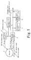
- FIG. 1 is a block diagram showing an example construction of a resolver detected position compensation system for a resolver, which embodies the resolver detected position compensation method of this invention.
- a resolver designated at reference numeral 1 has a rotor and excitation windings both not shown.
- the resolver 1 is mounted on a rotary shaft of a rotating apparatus such as motor, not shown, and outputs analog signals representing a rotational position of the rotary shaft of the rotating apparatus.
- this system has an excitation circuit 3, a position detection circuit 5, a reference signal oscillator 7 to supply a reference signal S to the excitation circuit 3 and the position detection circuit 5, and a dynamic error compensation circuit 9.
- the resolver 1 When an analog signal sin ⁇ t as an excitation signal S11 is supplied from the excitation circuit 3 to a stationary winding of the resolver 1, the resolver 1 outputs a sin ⁇ 0 ⁇ sin ⁇ t as an analog position signal S21 and a cos ⁇ 0 ⁇ sin ⁇ t as an analog position signal S22 to the position detection circuit 5.
- These output signals from the resolver 1 include so-called static errors.
- the static error is defined as an error from a real position that occurs when the rotor of the resolver 1 is at rest.
- the static error is caused by slight imbalance that exists in both electromagnetic characteristic of the core composed of electromagnetic steel plates and coil Impedance of both the stator and the rotor when the rotor is at rest.
- This static error is produced in the form of as many ripples, which appear during one complete rotation of the rotor through 360° mechanical angle, as the number of pole pairs of the resolver.
- the position detection circuit 5 performs a compensation to remove this static error from the output of the resolver 1 and outputs a compensated detected position signal ⁇ 0 .
- the method of compensating the static error is arbitrary. For example, a known compensation method described earlier in the background of the invention may be used.
- the compensated detected position signal ⁇ 0 that was produced by compensating the static error in the output from the position detection circuit 5 includes a dynamic error or dynamic error signal that changes (normally increases) with the rotation of the rotor of the resolver 1.
- the dynamic error compensation circuit 9 removes a component of this dynamic error (dynamic error signal) from the compensated detected position signal ⁇ 0 .
- This dynamic error varies its phase and amplitude peak value as the rotational speed of the rotor changes. The peak of amplitude of the dynamic error signal tends to increase with the rotational speed of the rotor, as shown in Fig. 2.
- the dynamic error component (dynamic error signal) changes or varies its phase relative to the reference position (position with no error) according to the rotational position of the rotor, as shown in Fig. 3.
- the dynamic error contains twice as many ripples, which appear during one rotation of the rotor of the resolver 1, as the number of pole pairs.
- Fig. 3 shows a reference of a phase variation of the dynamic error with respect to the rotor position at a particular speed. Multiplying the reference of the phase variation as shown in Fig. 3 by the amplitude peak value of the dynamic error at a particular speed as shown in Fig. 2 results in an estimated dynamic error signal.
- an amplitude peak value can be known by, for example, processing a differential signal of the compensated detected position signal ⁇ 0 by an analog FV (frequency-voltage) converter to obtain a speed change, viewing it on an oscilloscope and determining an amount of change. Then, this change is subjected to a fast Fourier cosine-sine transform (FFT) for a frequency analysis to determine a frequency component.
- FFT fast Fourier cosine-sine transform
- the dynamic error compensation circuit 9 has a differential circuit 11 to differentiate the compensated detected position signal ⁇ 0 and a dynamic error estimation circuit 13 to estimate a dynamic error.
- the dynamic error compensation circuit 9 compensates the dynamic error by calculating a dynamic error corresponding to a particular rotation speed of the rotor of the resolver 1 based on data measured beforehand to estimate the dynamic error as an estimated dynamic error and then subtracting the estimated dynamic error from the compensated detected position signal ⁇ 0 .
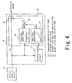
- Fig. 4 shows an example construction of the dynamic error compensation circuit 9.
- the dynamic error estimation circuit 13 has a phase data memory means 15, a peak value memory means 17, and a multiplication means 19 and a subtraction circuit 21.
- the phase data memory means 15 stores a phase variation of the dynamic error signal, that varies with the rotational speeds of the rotor of the resolver 1, as dynamic error phase data ⁇ L in respect of the waveform such as shown in Fig. 3 that was measured beforehand at various rotor positions.
- the peak value memory means 17 stores a variation of a peak value in amplitude of the dynamic error signal, that varies with the rotational speeds of the rotor, as dynamic error amplitude peak value data ⁇ H (characteristic data such as shown in Fig.
- the phase data memory means 15 and the peak value memory means 17 output to a multiplication means 19 the dynamic error phase data ⁇ L and the dynamic error amplitude peak value data ⁇ H that were read out according to the compensated detected position signal ⁇ 0 output from the position detection circuit 5 and the rotor rotational speed signal ⁇ o' output from the differential circuit 11.
- the multiplication means 19 multiplies the dynamic error phase data ⁇ L (the phase variation of the dynamic error signal) read from the phase data memory means 15 and the dynamic error amplitude peak value ( ⁇ H ) read from the peak value memory means 17 to produce an estimated dynamic error ⁇ E .
- the subtraction circuit 21 subtracts estimated dynamic error ⁇ E from the compensated detected position signal ⁇ 0 to output a compensated position data from which the dynamic error has been eliminated.
- the application of this invention is not limited in terms of resolver construction and excitation system, and the invention can be applied to the compensation of output of resolvers of various constructions or types.
Landscapes
- Engineering & Computer Science (AREA)
- Signal Processing (AREA)
- Physics & Mathematics (AREA)
- General Physics & Mathematics (AREA)
- Transmission And Conversion Of Sensor Element Output (AREA)
Applications Claiming Priority (2)
| Application Number | Priority Date | Filing Date | Title |
|---|---|---|---|
| JP2003276286A JP2005037305A (ja) | 2003-07-17 | 2003-07-17 | レゾルバの検出位置補正方法及び装置 |
| JP2003276286 | 2003-07-17 |
Publications (2)
| Publication Number | Publication Date |
|---|---|
| EP1498698A2 true EP1498698A2 (de) | 2005-01-19 |
| EP1498698A3 EP1498698A3 (de) | 2006-09-13 |
Family
ID=33475576
Family Applications (1)
| Application Number | Title | Priority Date | Filing Date |
|---|---|---|---|
| EP04254268A Withdrawn EP1498698A3 (de) | 2003-07-17 | 2004-07-16 | Ausgleichsverfahren einer detektierten Position eines Drehmelders |
Country Status (4)
| Country | Link |
|---|---|
| US (1) | US7047145B2 (de) |
| EP (1) | EP1498698A3 (de) |
| JP (1) | JP2005037305A (de) |
| CN (1) | CN1576850A (de) |
Cited By (2)
| Publication number | Priority date | Publication date | Assignee | Title |
|---|---|---|---|---|
| EP2211148A2 (de) | 2009-01-21 | 2010-07-28 | KUKA Roboter GmbH | Verfahren und Vorrichtung zur Bestimmung einer Winkellage mittels eines Resolvers |
| EP2275888A3 (de) * | 2009-07-04 | 2011-09-28 | Lenze Automation GmbH | Rotorlagegeber mit einer Kompensationseinheit zur Fehlerkompensation für einen drehzahlgeregelten Servomotor |
Families Citing this family (26)
| Publication number | Priority date | Publication date | Assignee | Title |
|---|---|---|---|---|
| JP4648948B2 (ja) * | 2005-06-24 | 2011-03-09 | パナソニック株式会社 | 無線受信装置 |
| KR100955549B1 (ko) * | 2005-11-28 | 2010-04-30 | 미쓰비시덴키 가부시키가이샤 | 위치 검출 오차 보정 방법 |
| US7469193B2 (en) * | 2006-11-16 | 2008-12-23 | Continental Automotive Systems Us, Inc. | Method and apparatus for resolver compensation |
| US8239154B2 (en) * | 2006-11-16 | 2012-08-07 | Continental Automotive Systems Us, Inc. | Method and apparatus for resolver compensation |
| US7863850B2 (en) * | 2007-05-11 | 2011-01-04 | GM Global Technology Operations LLC | Apparatus, system, and method for simulating outputs of a resolver to test motor-resolver systems |
| CN101821582B (zh) * | 2007-06-28 | 2013-04-17 | 海克斯康测量技术有限公司 | 用于确定测量机中的动态误差的方法 |
| WO2009012236A2 (en) * | 2007-07-13 | 2009-01-22 | P.C. Krause & Associates, Inc. | Adaptive resolver compensation controller |
| JP4950824B2 (ja) * | 2007-09-28 | 2012-06-13 | 株式会社東芝 | 回転機の制御装置、制御システムおよび制御方法 |
| US8179127B2 (en) * | 2007-11-06 | 2012-05-15 | GM Global Technology Operations LLC | Method and apparatus to monitor position of a rotatable shaft |
| JP5041419B2 (ja) * | 2007-12-28 | 2012-10-03 | 東芝機械株式会社 | レゾルバ装置およびレゾルバの角度検出装置とその方法 |
| JP5288859B2 (ja) * | 2008-03-31 | 2013-09-11 | 三菱電機株式会社 | 位置検出誤差補正装置および位置検出誤差補正方法 |
| US7977936B2 (en) * | 2008-10-16 | 2011-07-12 | Hamilton Sundstrand Corporation | Resolver interface and signal conditioner |
| JP4900738B2 (ja) | 2009-06-30 | 2012-03-21 | アイシン・エィ・ダブリュ株式会社 | 電動機駆動制御装置 |
| JP5522476B2 (ja) | 2010-12-10 | 2014-06-18 | アイシン・エィ・ダブリュ株式会社 | 制御装置 |
| JP5733250B2 (ja) * | 2012-03-27 | 2015-06-10 | 株式会社デンソー | 位置検出装置 |
| EP2888141B1 (de) | 2012-08-21 | 2019-08-28 | Allison Transmission, Inc. | System und verfahren zur fehlerkorrektur bei winkelpositionssensoren |
| US9068861B2 (en) * | 2012-08-24 | 2015-06-30 | Hamilton Sundstrand Corporation | Resolver interface |
| JP6165541B2 (ja) | 2013-07-26 | 2017-07-19 | Ntn株式会社 | 回転検出装置および回転検出装置付き軸受 |
| DE102015211260A1 (de) | 2015-06-18 | 2016-12-22 | Robert Bosch Gmbh | Verfahren und Vorrichtung zur Bestimmung eines Sensorsignals |
| US20170151875A1 (en) * | 2015-11-30 | 2017-06-01 | Faraday&Future Inc. | Detecting position measurement errors in an electric motor system |
| US20170174085A1 (en) | 2015-12-18 | 2017-06-22 | Hamilton Sundstrand Corporation | Permanent magnet synchronous generator based direct current power generating system |
| KR102462592B1 (ko) * | 2017-08-16 | 2022-11-04 | 현대자동차주식회사 | 레졸버 위치오차 보상장치 및 방법 |
| CN107769630B (zh) * | 2017-11-13 | 2020-09-22 | 中国航空工业集团公司西安航空计算技术研究所 | 一种永磁同步电机位置解码监控系统 |
| CN111092582B (zh) * | 2019-12-31 | 2021-10-08 | 潍柴动力股份有限公司 | 一种位置识别方法和相关装置 |
| EP4243275A1 (de) * | 2022-03-10 | 2023-09-13 | Braun GmbH | Kleines elektrisches gerät mit verbesserter motordrehzahlregelung |
| CN115575862B (zh) * | 2022-09-29 | 2023-06-09 | 北京航空航天大学 | 一种电动汽车旋转变压器系统的电磁敏感性测试装置及方法 |
Citations (2)
| Publication number | Priority date | Publication date | Assignee | Title |
|---|---|---|---|---|
| JPH07336979A (ja) * | 1994-06-06 | 1995-12-22 | Nippon Seiko Kk | 位置検出方法及び位置検出装置 |
| JP2001165707A (ja) * | 1999-09-30 | 2001-06-22 | Sanyo Denki Co Ltd | レゾルバの位相誤差補正方法及び装置 |
Family Cites Families (8)
| Publication number | Priority date | Publication date | Assignee | Title |
|---|---|---|---|---|
| US3395350A (en) * | 1962-12-14 | 1968-07-30 | Gen Precision Systems Inc | Method and apparatus for dynamic testing of resolvers |
| US4134106A (en) * | 1976-12-16 | 1979-01-09 | The Bendix Corporation | Absolute resolver angle to digital converter circuit |
| US5710509A (en) | 1995-10-30 | 1998-01-20 | Atsutoshi Goto | Phase difference detection device for an inductive position detector |
| JP3368837B2 (ja) | 1998-08-05 | 2003-01-20 | トヨタ自動車株式会社 | レゾルバ信号処理装置 |
| DE19841763C1 (de) | 1998-09-11 | 2000-02-10 | Texas Instruments Deutschland | Verfahren zur digitalen Auswertung der analogen Ausgangssignale eines Resolvers |
| JP3047231B1 (ja) | 1999-04-02 | 2000-05-29 | 士郎 嶋原 | レゾルバ |
| JP4355395B2 (ja) | 1999-05-19 | 2009-10-28 | 株式会社アミテック | 位置検出データ生成方法及び装置 |
| US6415237B1 (en) * | 1999-10-12 | 2002-07-02 | Texas Instruments Incorporated | Electronic correction for rotary transducer spin frequency noise |
-
2003
- 2003-07-17 JP JP2003276286A patent/JP2005037305A/ja active Pending
-
2004
- 2004-07-14 CN CN200410064054.0A patent/CN1576850A/zh active Pending
- 2004-07-16 US US10/893,454 patent/US7047145B2/en not_active Expired - Lifetime
- 2004-07-16 EP EP04254268A patent/EP1498698A3/de not_active Withdrawn
Patent Citations (2)
| Publication number | Priority date | Publication date | Assignee | Title |
|---|---|---|---|---|
| JPH07336979A (ja) * | 1994-06-06 | 1995-12-22 | Nippon Seiko Kk | 位置検出方法及び位置検出装置 |
| JP2001165707A (ja) * | 1999-09-30 | 2001-06-22 | Sanyo Denki Co Ltd | レゾルバの位相誤差補正方法及び装置 |
Cited By (4)
| Publication number | Priority date | Publication date | Assignee | Title |
|---|---|---|---|---|
| EP2211148A2 (de) | 2009-01-21 | 2010-07-28 | KUKA Roboter GmbH | Verfahren und Vorrichtung zur Bestimmung einer Winkellage mittels eines Resolvers |
| EP2211148A3 (de) * | 2009-01-21 | 2011-06-15 | KUKA Laboratories GmbH | Verfahren und Vorrichtung zur Bestimmung einer Winkellage mittels eines Resolvers |
| US8427141B2 (en) | 2009-01-21 | 2013-04-23 | Kuka Laboratories Gmbh | Method and device to determine a relative position using a resolver |
| EP2275888A3 (de) * | 2009-07-04 | 2011-09-28 | Lenze Automation GmbH | Rotorlagegeber mit einer Kompensationseinheit zur Fehlerkompensation für einen drehzahlgeregelten Servomotor |
Also Published As
| Publication number | Publication date |
|---|---|
| EP1498698A3 (de) | 2006-09-13 |
| US20050033539A1 (en) | 2005-02-10 |
| US7047145B2 (en) | 2006-05-16 |
| CN1576850A (zh) | 2005-02-09 |
| JP2005037305A (ja) | 2005-02-10 |
Similar Documents
| Publication | Publication Date | Title |
|---|---|---|
| US7047145B2 (en) | Compensation method of resolver detected position | |
| KR102099075B1 (ko) | 각 위치 센서들에서의 에러 정정을 위한 시스템 및 방법 | |
| EP1061640B1 (de) | Verfahren und Vorrichtung zur Bestromung der Statorwindungen einer drehenden elektrischen Maschine | |
| KR101885009B1 (ko) | 위치 검출기의 각도 오차 보정 장치 및 각도 오차 보정 방법 | |
| Raca et al. | Robust magnet polarity estimation for initialization of PM synchronous machines with near-zero saliency | |
| JP2000270600A (ja) | 誘導モータドライブ及びそのパラメータ評価方法 | |
| CN118137916A (zh) | 转子角度估算动态补偿方法 | |
| KR101335162B1 (ko) | 레졸버를 위한 위치 오차 보정 장치 및 보정 방법 | |
| EP1729405A1 (de) | Gerät zur Drehzahlregelung eines feldorientiert geregelten Wechselstrommotors | |
| US20200228034A1 (en) | Method and device for estimating the torque ripple of an electric motor | |
| US20030033103A1 (en) | Position detection data generating method and apparatus based on phase shift principle | |
| Despalatović et al. | Real-time power angle determination of salient-pole synchronous machine based on air gap measurements | |
| EP4441882B1 (de) | Hochpräzise rotorpositionsbestimmung zur verwendung in der positions- und/oder drehmomentsteuerung bei niedriger drehzahl | |
| JPH0221266A (ja) | 直流モータの回転測定方法 | |
| US20200195176A1 (en) | Device and method for controlling rotary electric machine | |
| JP7606524B2 (ja) | 同期電気機械の電磁トルクを推定するための方法 | |
| US20050016279A1 (en) | Measurement of motions of rotating shafts using non-vibrating contact potential difference sensor | |
| JP3182205B2 (ja) | 磁気軸受装置 | |
| EP1218754A1 (de) | Strom-Drehmoment-Vergleich zur Plausibilitäts-untersuchung in einer elektrischenMaschine mit permanet Magneten | |
| JP6673175B2 (ja) | 誘導電動機の制御システム | |
| Wang et al. | Methods for Detecting and Compensating Position Estimation Error Caused by Cross Saturation in Sensorless Control of SynRM | |
| EP1073193B1 (de) | Steuerverfahren eines sensorlosen Induktionsmotors | |
| KR20180038656A (ko) | 교류전동기의 회전자 위치보정 방법 및 그 장치 | |
| Wang et al. | Sensorless speed measurement of induction machines using short time Fourier transformation | |
| Jarzebowicz et al. | Angle tracking observer for filtering rotor position estimates in sensorless electric drives |
Legal Events
| Date | Code | Title | Description |
|---|---|---|---|
| PUAI | Public reference made under article 153(3) epc to a published international application that has entered the european phase |
Free format text: ORIGINAL CODE: 0009012 |
|
| AK | Designated contracting states |
Kind code of ref document: A2 Designated state(s): AT BE BG CH CY CZ DE DK EE ES FI FR GB GR HU IE IT LI LU MC NL PL PT RO SE SI SK TR |
|
| AX | Request for extension of the european patent |
Extension state: AL HR LT LV MK |
|
| PUAL | Search report despatched |
Free format text: ORIGINAL CODE: 0009013 |
|
| AK | Designated contracting states |
Kind code of ref document: A3 Designated state(s): AT BE BG CH CY CZ DE DK EE ES FI FR GB GR HU IE IT LI LU MC NL PL PT RO SE SI SK TR |
|
| AX | Request for extension of the european patent |
Extension state: AL HR LT LV MK |
|
| AKX | Designation fees paid |
Designated state(s): DE FR GB |
|
| 17P | Request for examination filed |
Effective date: 20070219 |
|
| 17Q | First examination report despatched |
Effective date: 20110428 |
|
| STAA | Information on the status of an ep patent application or granted ep patent |
Free format text: STATUS: THE APPLICATION IS DEEMED TO BE WITHDRAWN |
|
| 18D | Application deemed to be withdrawn |
Effective date: 20110909 |