EP1498693A2 - Verfahren und Vorrichtung zum Messen physikalischer Grössen - Google Patents
Verfahren und Vorrichtung zum Messen physikalischer Grössen Download PDFInfo
- Publication number
- EP1498693A2 EP1498693A2 EP04015916A EP04015916A EP1498693A2 EP 1498693 A2 EP1498693 A2 EP 1498693A2 EP 04015916 A EP04015916 A EP 04015916A EP 04015916 A EP04015916 A EP 04015916A EP 1498693 A2 EP1498693 A2 EP 1498693A2
- Authority
- EP
- European Patent Office
- Prior art keywords
- vibrator
- detection
- vibration
- driving
- film
- Prior art date
- Legal status (The legal status is an assumption and is not a legal conclusion. Google has not performed a legal analysis and makes no representation as to the accuracy of the status listed.)
- Granted
Links
- 238000000034 method Methods 0.000 title claims abstract description 16
- 238000001514 detection method Methods 0.000 claims abstract description 71
- 238000005452 bending Methods 0.000 claims description 19
- 238000005530 etching Methods 0.000 claims description 3
- PCHJSUWPFVWCPO-UHFFFAOYSA-N gold Chemical compound [Au] PCHJSUWPFVWCPO-UHFFFAOYSA-N 0.000 description 12
- 229910052737 gold Inorganic materials 0.000 description 12
- 239000010931 gold Substances 0.000 description 12
- VYZAMTAEIAYCRO-UHFFFAOYSA-N Chromium Chemical compound [Cr] VYZAMTAEIAYCRO-UHFFFAOYSA-N 0.000 description 6
- BQCADISMDOOEFD-UHFFFAOYSA-N Silver Chemical compound [Ag] BQCADISMDOOEFD-UHFFFAOYSA-N 0.000 description 6
- RTAQQCXQSZGOHL-UHFFFAOYSA-N Titanium Chemical compound [Ti] RTAQQCXQSZGOHL-UHFFFAOYSA-N 0.000 description 6
- 229910052804 chromium Inorganic materials 0.000 description 6
- 239000011651 chromium Substances 0.000 description 6
- 229910052709 silver Inorganic materials 0.000 description 6
- 239000004332 silver Substances 0.000 description 6
- 229910052719 titanium Inorganic materials 0.000 description 6
- 239000010936 titanium Substances 0.000 description 6
- 230000005484 gravity Effects 0.000 description 5
- 229910052751 metal Inorganic materials 0.000 description 5
- 239000002184 metal Substances 0.000 description 5
- 229920002120 photoresistant polymer Polymers 0.000 description 5
- 239000010453 quartz Substances 0.000 description 5
- VYPSYNLAJGMNEJ-UHFFFAOYSA-N silicon dioxide Inorganic materials O=[Si]=O VYPSYNLAJGMNEJ-UHFFFAOYSA-N 0.000 description 5
- GWEVSGVZZGPLCZ-UHFFFAOYSA-N Titan oxide Chemical compound O=[Ti]=O GWEVSGVZZGPLCZ-UHFFFAOYSA-N 0.000 description 4
- 239000013078 crystal Substances 0.000 description 4
- 239000000463 material Substances 0.000 description 4
- 229910044991 metal oxide Inorganic materials 0.000 description 4
- 150000004706 metal oxides Chemical class 0.000 description 4
- BASFCYQUMIYNBI-UHFFFAOYSA-N platinum Chemical compound [Pt] BASFCYQUMIYNBI-UHFFFAOYSA-N 0.000 description 4
- 238000004544 sputter deposition Methods 0.000 description 3
- 241000251131 Sphyrna Species 0.000 description 2
- 230000001133 acceleration Effects 0.000 description 2
- 230000008901 benefit Effects 0.000 description 2
- 230000008859 change Effects 0.000 description 2
- 238000012937 correction Methods 0.000 description 2
- 238000007772 electroless plating Methods 0.000 description 2
- 238000009713 electroplating Methods 0.000 description 2
- 230000002093 peripheral effect Effects 0.000 description 2
- 229910052697 platinum Inorganic materials 0.000 description 2
- 238000007740 vapor deposition Methods 0.000 description 2
- 229910003327 LiNbO3 Inorganic materials 0.000 description 1
- 229910012463 LiTaO3 Inorganic materials 0.000 description 1
- WHXSMMKQMYFTQS-UHFFFAOYSA-N Lithium Chemical compound [Li] WHXSMMKQMYFTQS-UHFFFAOYSA-N 0.000 description 1
- 230000002411 adverse Effects 0.000 description 1
- 238000013459 approach Methods 0.000 description 1
- 230000008878 coupling Effects 0.000 description 1
- 238000010168 coupling process Methods 0.000 description 1
- 238000005859 coupling reaction Methods 0.000 description 1
- 238000013461 design Methods 0.000 description 1
- 238000010586 diagram Methods 0.000 description 1
- 230000000694 effects Effects 0.000 description 1
- 230000001678 irradiating effect Effects 0.000 description 1
- 230000001788 irregular Effects 0.000 description 1
- 229910052744 lithium Inorganic materials 0.000 description 1
- 230000007246 mechanism Effects 0.000 description 1
- 238000012986 modification Methods 0.000 description 1
- 230000004048 modification Effects 0.000 description 1
- 229910052758 niobium Inorganic materials 0.000 description 1
- 238000000059 patterning Methods 0.000 description 1
- 239000006104 solid solution Substances 0.000 description 1
- 229910052715 tantalum Inorganic materials 0.000 description 1
- RIUWBIIVUYSTCN-UHFFFAOYSA-N trilithium borate Chemical compound [Li+].[Li+].[Li+].[O-]B([O-])[O-] RIUWBIIVUYSTCN-UHFFFAOYSA-N 0.000 description 1
Images




Classifications
-
- G—PHYSICS
- G01—MEASURING; TESTING
- G01C—MEASURING DISTANCES, LEVELS OR BEARINGS; SURVEYING; NAVIGATION; GYROSCOPIC INSTRUMENTS; PHOTOGRAMMETRY OR VIDEOGRAMMETRY
- G01C19/00—Gyroscopes; Turn-sensitive devices using vibrating masses; Turn-sensitive devices without moving masses; Measuring angular rate using gyroscopic effects
- G01C19/56—Turn-sensitive devices using vibrating masses, e.g. vibratory angular rate sensors based on Coriolis forces
- G01C19/5607—Turn-sensitive devices using vibrating masses, e.g. vibratory angular rate sensors based on Coriolis forces using vibrating tuning forks
Definitions
- the present invention relates to a method and device of measuring a physical quantity.
- the gyroscope In an application of mounting a vibratory gyroscope on a vehicle, the gyroscope is used in an extremely wide temperature range. For example, it is required that the gyroscope properly functions in a wide temperature range of - 40 °C to +85 °C. Even when the resonance frequency of a pair of bending vibration arms is adjusted at a constant quantity at room temperature, the change and deviation of the resonance frequency may be large as the temperature is considerably changed to a high or low temperature. The change or deviation of resonance frequency thus results in a so-called zero point temperature drift.
- the assignee filed a Japanese Patent publication 2000- 107725A, and disclosed that tapered parts are provided at both roots of a bending vibration arm on both sides, respectively, to reduce the zero point temperature drift.
- the inventors have studied such technique and found the following problems, depending on the material of the vibrator. That is, as described in Japanese patent publication 2000-107725A, tapered parts are provided in the roots of the side faces of a bending vibration arm so that the tapered parts have substantially the same planar shape. It is considered that the vibration mode of the bending vibration arm may be made more symmetrical to reduce the zero point temperature drift. When the zero point temperature drift is measured for each of vibrators actually fabricated, however, the drift may be deviated among the vibrators. The deviation of zero point temperature drift may be increased so that the yield of off-specification products is increased.
- a photoresist is applied on both of upper and lower faces of a wafer.
- Photo masks are mounted on the photoresists, and the photo masks on the upper and lower faces are aligned with each other.
- the photoresist are exposed to light to harden it, and the photo masks are removed to complete the patterning of the photo resists.
- the wafer is then etched so that an outline corresponding with the pattern of the photoresist is formed on the wafer.
- An object of the present invention is to reduce a noise and temperature drift due to unbalance of the shape of a vibrator actually produced, when the vibrator is used for measuring a physical quantity.
- the present invention provides a method of measuring a physical quantity using a vibrator.
- the vibrator comprises a plurality of driving vibration arms, a plurality of detection vibration arms, films for adjusting a weight provided on said driving vibration arms, respectively and detecting means provided on said detection vibration arms, respectively.
- the method comprises the steps of:
- the present invention when a driving vibration is excited in a vibrator, output signals are output from the detecting means based on a detection vibration excited in the vibrator responsive to the physical quantity.
- the weight of each of the films is adjusted based on a comparison of the output signals from the detection vibration arms. After the adjustment, the ratio of the weights of the driving vibration arms is changed, so that the pattern and mode of the driving vibration are slightly changed as well as those of the detection vibration. It is thus possible to adjust the weights of the films so that the noises in the output signal drawn from the detecting means are reduced.
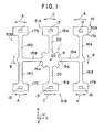
- the vibrator 14 has a base part 1, a pair of driving vibration systems 30A, 390B and a pair of detection vibration systems 31A, 31B.
- the base part 1 of the present example has a square shape of quad-symmetrical with respect to the center of gravity GO (the center of gravity when the vibrator is not vibrated) of the vibrator.
- the driving vibration systems 30A, 30B and detection vibration systems 31A, 31B are protruded from the fixing part 1, respectively, at the respective sides 1a.
- the driving vibration systems 30A and 30B have elongate supporting portions 15A and 15B protruding from the peripheral part 1a of the base portion 1 in radial directions and a pair of driving vibration arms 16A, 16B and 16C, 16D protruding in a direction perpendicular to the longitudinal direction of the supporting portions 15A and 15B, respectively.
- wide weight portions or hammer heads 17A, 17B, 17C and 17D are provided at the tip ends of the driving vibration arms, respectively.
- a through hole 12 is formed in each of the weight portions.
- Each of the detection vibration systems 31A and 13B comprises an elongate detection vibration arm 20 protruding in a radial direction from the peripheral part 1a of the base portion 1.
- Wide weight portions or hammer heads 18A and 18B are provided at the tip ends of the detection vibration arms 20.
- a through hole 13 is formed in each of the weight portions.
- Each of the driving vibration arms 16A and 16B is vibrated in bending vibration mode as an arrow "A" in the same phase using driving electrodes as described later, and each of the driving vibration arms 16C and 16D is vibrated in bending vibration mode as an arrow "A” in the same phase.
- the center of gravity of the whole driving vibration of the bending vibration arms 16A to 16D is positioned on or near the center of gravity "GO" of the vibrator.
- the vibrator 14 In the detection vibration mode, the vibrator 14 is turned in a specified plane (X-Y plane) as an arrow ⁇ . Responsive to the turning, Colioris force is applied on the vibrator 14, so that the supporting parts 15A and 15B are vibrated in bending motion as an arrow "B" around the root 15a.
- the phases of the bending vibration modes of the supporting portions 15A and 15B are in inverse phase with respect to the center of gravity "GO". Responsive to this, each of the detection vibration pieces 20 is vibrated as an arrow "C" in bending mode around the root to the base portion 1.
- a signal voltage is induced in each signal electrode as described later.
- a turning angular rate is calculated based on the signal voltages.
- Fig. 2 is a plan view showing electrode pattern of the base portion 1.
- Fig. 3 is a plan view showing a part of electrode pattern on the surface of the vibrator, and
- Fig. 4 is a plan view showing the whole of the electrode pattern on the surface of the vibrator.
- Ground electrodes 22 for driving are provided on the surfaces (and back faces not shown) of the driving vibration arms 16A and 16B, respectively.
- Signal electrodes 10 for driving are provided on the side faces, respectively.
- Signal electrodes 11 for driving are provided on the surfaces (and back faces not shown) of the driving vibration arms 16C and 16D, respectively, and ground electrodes 32 for driving are provided on the side faces, respectively. Alternating current voltages are applied on the signal electrodes 10 and 11 for driving and ground electrodes 22 and 32 for driving, respectively, so that the driving vibration arms are vibrated in bending motion along an X-Y plane.
- Signal electrodes 8 for detection are provided on the surface (and the back face not shown) of the detection vibration arms 20, respectively, and ground electrodes 9 for detection are provided on the side faces. As the detection vibration arms are vibrated in bending motion along an X-Y plane, alternating current and signal voltages are induced between the signal electrodes 8 for detection and ground electrodes 9 for detection.
- signal pads 2B for driving, ground pads 3B for driving, two signal pads 4C and 4D for detection and ground pads 5C and 5D for detection are provided on the surface of the base portion 1.
- Each of the signal electrodes 10 and 11 for driving is electrically connected to the signal pad 2B for driving on the base portion 1 through a wiring 38.
- Each of the ground electrodes 22 and 32 for driving is electrically connected to the ground pad 3B for detection on the base portion 1 through a wiring 21.
- the ground pads 3B for driving are connected to a pair of wirings 6as and 6B, which surround the signal pads 2B for driving and connected to wirings 6C and 6D on the edge of the base portion 1.
- the wirings 6C and 6D are provided on the surface of the base portion 1.
- the wirings 6A and 6D are communicated with wirings 7 on the side faces and ground wirings 23A and 23B on the surface of the supporting portion 15B, respectively.
- the signal pads 4C and 4D for detection are electrically connected with the signal electrodes 8 for detection, respectively.
- the ground pads 5C and 5D for detection are connected with the ground electrodes 9 for detection on the side faces of the detection vibration arm, respectively.
- a plurality of signal pads 4C and 4D are provided at positions symmetrical with respect to a straight line "X" connecting the signal pad 2B for driving and ground pad 3B for driving. It is thus possible to cancel electrostatic couplings of the signal pads for driving and signal pads 4C and 4D for detection. Further, according to the present example, a plurality of ground pads 5C and 5D are provided at positions symmetrical with respect to the straight line "X".
- Films D1, D2, D3 and D4 for adjusting weight are provided on the weight portions 17A, 17B, 17C and 17D of the driving vibration arms, respectively.
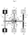
- the unbalance of the weights of the driving vibration arms 16A, 16B, 16C and 16D results in, for example, distribution of dislocation shown in Fig. 6 (driving vibration mode) after the frequency of driving vibration is adjusted.
- Fig. 6 driving vibration mode
- a region having a larger dislocation (lower lightness) is elongated diagonally across the base portion 1.
- the driving vibration having such irregular dislocation distribution may result in a detection vibration in which the detection vibration arm is dislocated in the direction of Z-axis (a direction perpendicular to the paper face).
- the dislocation of the detection vibration arm in the direction of Z-axis results in a noise in a detection signal.
- the dislocations are substantially symmetrical with respect to the center vertical line in the base portion 1, as shown in Fig. 7.
- the unbalance When the unbalance is induced, for example, as shown in Fig. 6, the unbalance adversely affects the detection signal as the noise in each detection signal.
- the detection signals output from a plurality of the detection means are compared with each other to obtain the differences to be monitored.
- the weights of the films D1 to D4 are subject to adjustment so that the differences approach a specific quantity. A method of the adjustment is exemplified in table 1.
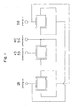
- a voltage signal is applied on the signal pads 2B for driving and ground pads 3B for detection, for example, from a circuit shown in Fig. 5 to excite driving vibration in the driving vibration arms. Detection vibration is thus excited in the detection vibration arms to provide output signals.
- the potentials of the signal pads 4C and 4D for detection with respect to the ground pads 5C and 5D for detection are assigned output signals P1 and P2, respectively.
- the frequency of the detection vibration is higher than that of the driving vibration
- the frequency of a spurious vibration is higher than that of the driving vibration
- the output signal P1 is larger than P2 and the phase of P1 is positive.
- the weight of the weight adjusting film D2 is removed. It is thus possible to reduce the weight of the driving vibration arm having the film D2 and the unbalance of the driving vibration.
- the frequency of the detection vibration is higher than that of the driving vibration, the frequency of a spurious vibration is higher than that of the driving vibration, the output signal P1 is larger than P2 and the phase of P1 is negative. In this case, the weight of the weight adjusting film D4 is removed.
- the frequency of the detection vibration is higher than that of the driving vibration, the frequency of a spurious vibration is higher than that of the driving vibration, the output signal P1 is smaller than P2 and the phase of P1 is positive.
- the weight of the weight adjusting film D1 is removed. It is provided that the frequency of the detection vibration is higher than that of the driving vibration, the frequency of a spurious vibration is higher than that of the driving vibration, the out put signal P1 is smaller than P2 and the phase of P1 is negative. In this case, the weight of the weight adjusting film D3 is removed. In the other cases, the weight adjusting film subjected to the removal of weight is selected as shown in table 1.
- the material for the weight adjusting film may particularly preferably be a metal film or metal oxide film.
- the metal film for the weight adjusting film may preferably be a gold film, a multilayer film of gold and chromium, a multilayer film of gold and titanium, silver film, a multilayer film of silver and chromium, a multilayer film of silver and titanium, a lead film or platinum film.
- the metal oxide film may preferably be TiO 2 film.
- gold film is selected as the metal film, the controllability of the vibrations can be improved and the properties of the weight adjusting film can be maintained over a long time period due to a large specific weight of gold. Because a gold film has poor adherence with an oxide film such as quartz film, however, it is preferred to provide an underlayer such as chromium or titanium film between the vibration arm such as an arm made of quartz and the gold film.
- the weight adjusting film may be produced by any known methods such as vacuum vapor deposition, sputtering, electroplating, electroless plating or the like.
- a part of the material may be removed from the film by irradiating laser beam onto the film or reverse sputtering.
- the material of the vibrator is not particularly limited, and may preferably be a piezoelectric single crystal such as quartz, LiNbO 3 , LiTaO 3 , lithium niobate-lithium tantalate solid solution (Li(Nb, Ta)O 3 ) single crystal, lithium borate single crystal or langasite single crystal.
- a piezoelectric single crystal such as quartz, LiNbO 3 , LiTaO 3 , lithium niobate-lithium tantalate solid solution (Li(Nb, Ta)O 3 ) single crystal, lithium borate single crystal or langasite single crystal.
- the wiring, electrodes and pads may be composed of a conductive film.
- a conductive film may preferably be a metal film such as a gold film, a multilayer film of gold and chromium, a multilayer film of gold and titanium, silver film, a multilayer film of silver and chromium, a multilayer film of silver and titanium, a lead film or platinum film, or a metal oxide film such as TiO 2 .
- a gold film has poor adherence with an oxide film such as quartz film, however, it is preferred to provide an underlayer such as chromium or titanium film between the vibration arm such as an arm made of quartz and the gold film.
- the wiring, electrodes and pads may be produced by any known methods such as vacuum vapor deposition, sputtering, electroplating, electroless plating or the like.
- a physical quantity measured according to the present invention is not particularly limited.
- the physical quantity is included in the present invention as far as the physical quantity can be detected through a detection circuit.
- Such physical quantity may preferably be an acceleration, an angular acceleration or an angular velocity applied on a vibrator.
- the measuring system of the present invention may preferably be an inertia censor.
- the present invention may preferably be applied to a vibratory gyroscope of so-called horizontal setting type.
- a vibrator is elongated along a specified plane substantially perpendicular to a rotating axis.
- both of the driving and detection vibration arms vibrate along the specified plane.
- Figs. 1 to 4 relates to this embodiment of the present invention.
- the present invention provides a method of measuring a physical quantity using a vibrator.
- the vibrator 14 has a plurality of driving vibration arms 16A, 16B, 16C and 16D, a plurality of detection vibration arms 20, films D1, D2, D3 and D4 for adjusting a weight provided on the driving vibration arms, respectively, and detecting means 8 and 9 provided on the detection vibration arms, respectively.
- a driving vibration is excited in the vibrator 14, and output signals are output from the detecting means based on a detection vibration excited in the vibrator responsive to the physical quantity.
- the weight of each of the films is adjusted based on a comparison of the output signals P1 and P2 from the detection vibration arms.
Landscapes
- Physics & Mathematics (AREA)
- Engineering & Computer Science (AREA)
- General Physics & Mathematics (AREA)
- Radar, Positioning & Navigation (AREA)
- Remote Sensing (AREA)
- Gyroscopes (AREA)
- Measurement Of Mechanical Vibrations Or Ultrasonic Waves (AREA)
Applications Claiming Priority (2)
| Application Number | Priority Date | Filing Date | Title |
|---|---|---|---|
| JP2003274210A JP4163067B2 (ja) | 2003-07-14 | 2003-07-14 | 物理量測定方法および装置 |
| JP2003274210 | 2003-07-14 |
Publications (3)
| Publication Number | Publication Date |
|---|---|
| EP1498693A2 true EP1498693A2 (de) | 2005-01-19 |
| EP1498693A3 EP1498693A3 (de) | 2006-05-17 |
| EP1498693B1 EP1498693B1 (de) | 2008-07-02 |
Family
ID=33475547
Family Applications (1)
| Application Number | Title | Priority Date | Filing Date |
|---|---|---|---|
| EP04015916A Expired - Lifetime EP1498693B1 (de) | 2003-07-14 | 2004-07-06 | Verfahren und Vorrichtungen zum Messen physikalischer Grössen |
Country Status (4)
| Country | Link |
|---|---|
| US (1) | US7168289B2 (de) |
| EP (1) | EP1498693B1 (de) |
| JP (1) | JP4163067B2 (de) |
| DE (1) | DE602004014684D1 (de) |
Cited By (1)
| Publication number | Priority date | Publication date | Assignee | Title |
|---|---|---|---|---|
| EP1503177A2 (de) | 2003-07-25 | 2005-02-02 | Seiko Epson Corporation | Piezoelektrisches Schwingelement, Struktur zu seiner Halterung, piezoelektrischer Schwinger und piezoelektrischer Schwingkreisel |
Families Citing this family (22)
| Publication number | Priority date | Publication date | Assignee | Title |
|---|---|---|---|---|
| US7370531B2 (en) * | 2004-01-20 | 2008-05-13 | Ngk Insulators, Ltd. | Detection circuits, detection method and systems of measuring physical quantities |
| JP4123171B2 (ja) * | 2004-03-08 | 2008-07-23 | ソニー株式会社 | 振動型ジャイロセンサ素子の製造方法、振動型ジャイロセンサ素子及び振動方向調整方法 |
| JP4671284B2 (ja) * | 2005-08-30 | 2011-04-13 | 日本碍子株式会社 | 振動型ジャイロスコープ用測定素子 |
| JP4771062B2 (ja) * | 2005-09-26 | 2011-09-14 | セイコーエプソン株式会社 | 振動型ジャイロスコープ用測定素子 |
| ES2599031T3 (es) * | 2008-05-09 | 2017-01-31 | Grünenthal GmbH | Proceso para la preparación de una formulación de polvo intermedia y una forma de dosificación solida final utilizando un paso de congelación por pulverización |
| JP5360676B2 (ja) * | 2008-10-31 | 2013-12-04 | セイコーエプソン株式会社 | 角速度検出装置の製造方法 |
| JP5560806B2 (ja) * | 2010-03-19 | 2014-07-30 | セイコーエプソン株式会社 | ジャイロ素子、ジャイロセンサー、および電子機器 |
| JP2011220997A (ja) * | 2010-03-26 | 2011-11-04 | Seiko Epson Corp | 物理量検出素子、物理量検出装置、および電子機器 |
| JP4849284B2 (ja) * | 2010-12-27 | 2012-01-11 | セイコーエプソン株式会社 | 振動型ジャイロスコープ用測定素子 |
| JP5772286B2 (ja) * | 2011-06-24 | 2015-09-02 | セイコーエプソン株式会社 | 屈曲振動片及び電子機器 |
| JP5870532B2 (ja) * | 2011-08-09 | 2016-03-01 | セイコーエプソン株式会社 | 物理量検出素子、物理量検出装置および電子機器 |
| US8552625B1 (en) * | 2011-09-26 | 2013-10-08 | Image Acoustics, Inc. | Cantilever type acoustic transduction apparatus |
| US8659211B1 (en) | 2011-09-26 | 2014-02-25 | Image Acoustics, Inc. | Quad and dual cantilever transduction apparatus |
| US20140238129A1 (en) * | 2011-10-24 | 2014-08-28 | Panasonic Corporation | Angular velocity sensor and detection element used in same |
| US9322701B2 (en) | 2013-08-02 | 2016-04-26 | Qualcomm Incorporated | Dynamic force sensing to determine mass using a smartphone |
| JP5700090B2 (ja) * | 2013-09-05 | 2015-04-15 | セイコーエプソン株式会社 | 角速度検出装置の製造方法 |
| US20170059393A1 (en) | 2015-08-26 | 2017-03-02 | Seiko Epson Corporation | Physical Quantity Detection Device, Manufacturing Method For Physical Quantity Detection Device, Electronic Apparatus, And Moving Object |
| US11054259B2 (en) | 2016-07-26 | 2021-07-06 | Kyocera Corporation | Angular velocity sensor, sensor element, and multi-axis angular velocity sensor |
| US11835338B2 (en) | 2017-01-24 | 2023-12-05 | Kyocera Corporation | Sensor element, angular velocity sensor, and multi-axis angular velocity sensor |
| JP6833049B2 (ja) | 2017-08-29 | 2021-02-24 | 京セラ株式会社 | 角速度センサおよびセンサ素子 |
| JP7139610B2 (ja) | 2018-01-23 | 2022-09-21 | セイコーエプソン株式会社 | 振動素子、振動素子の製造方法、物理量センサー、慣性計測装置、電子機器および移動体 |
| JP7251385B2 (ja) * | 2019-07-30 | 2023-04-04 | セイコーエプソン株式会社 | 振動デバイス、電子機器および移動体 |
Family Cites Families (11)
| Publication number | Priority date | Publication date | Assignee | Title |
|---|---|---|---|---|
| US4791815A (en) * | 1986-04-11 | 1988-12-20 | Matsushita Electric Industrial Co., Ltd. | Cyclically driven gyro and adjusting system therefor |
| US4930351A (en) * | 1988-03-24 | 1990-06-05 | Wjm Corporation | Vibratory linear acceleration and angular rate sensing system |
| EP0806631B1 (de) | 1993-02-03 | 2001-11-07 | Matsushita Electric Industrial Co., Ltd. | Drehratensensor und Verfahren zu dessen Herstellung |
| JPH07113645A (ja) * | 1993-10-15 | 1995-05-02 | Toyota Motor Corp | 振動ジャイロ |
| JP3326989B2 (ja) | 1994-08-25 | 2002-09-24 | 株式会社豊田中央研究所 | 振動子とその調整方法および角速度センサ |
| US6065339A (en) | 1996-03-29 | 2000-05-23 | Ngk Insulators, Ltd. | Vibration gyro sensor, combined sensor and method for producing vibration gyro sensor |
| US5998911A (en) * | 1996-11-26 | 1999-12-07 | Ngk Insulators, Ltd. | Vibrator, vibratory gyroscope, and vibration adjusting method |
| JP3999377B2 (ja) * | 1997-11-04 | 2007-10-31 | 日本碍子株式会社 | 振動子、振動型ジャイロスコープ、直線加速度計および回転角速度の測定方法 |
| JP4107768B2 (ja) | 1999-07-01 | 2008-06-25 | 日本碍子株式会社 | 振動子および振動型ジャイロスコープ |
| US7523537B1 (en) | 2000-07-13 | 2009-04-28 | Custom Sensors & Technologies, Inc. | Method of manufacturing a tuning fork with reduced quadrature errror and symmetrical mass balancing |
| JP4305623B2 (ja) | 2002-03-13 | 2009-07-29 | セイコーエプソン株式会社 | 振動子および振動型ジャイロスコープ |
-
2003
- 2003-07-14 JP JP2003274210A patent/JP4163067B2/ja not_active Expired - Fee Related
-
2004
- 2004-06-24 US US10/876,361 patent/US7168289B2/en not_active Expired - Fee Related
- 2004-07-06 EP EP04015916A patent/EP1498693B1/de not_active Expired - Lifetime
- 2004-07-06 DE DE602004014684T patent/DE602004014684D1/de not_active Expired - Lifetime
Cited By (2)
| Publication number | Priority date | Publication date | Assignee | Title |
|---|---|---|---|---|
| EP1503177A2 (de) | 2003-07-25 | 2005-02-02 | Seiko Epson Corporation | Piezoelektrisches Schwingelement, Struktur zu seiner Halterung, piezoelektrischer Schwinger und piezoelektrischer Schwingkreisel |
| EP1503177B1 (de) * | 2003-07-25 | 2016-04-13 | Seiko Epson Corporation | Piezoelektrisches Schwingelement, Struktur zu seiner Halterung, piezoelektrischer Schwinger und piezoelektrischer Schwingkreisel |
Also Published As
| Publication number | Publication date |
|---|---|
| US7168289B2 (en) | 2007-01-30 |
| DE602004014684D1 (de) | 2008-08-14 |
| JP2005037235A (ja) | 2005-02-10 |
| EP1498693A3 (de) | 2006-05-17 |
| US20050011267A1 (en) | 2005-01-20 |
| EP1498693B1 (de) | 2008-07-02 |
| JP4163067B2 (ja) | 2008-10-08 |
Similar Documents
| Publication | Publication Date | Title |
|---|---|---|
| US7168289B2 (en) | Method and devices of measuring physical quantities | |
| US6698292B2 (en) | Vibrators and vibratory gyroscopes | |
| EP0649002B1 (de) | Vibrationskreisel | |
| US6439051B2 (en) | Vibrators, vibratory gyroscopes, devices for measuring a linear acceleration and a method of measuring a turning angular rate | |
| US9366535B2 (en) | Vibration gyro element, gyro sensor, and electronic apparatus | |
| WO2006036022A1 (ja) | 振動型ジャイロスコープ、及び振動型ジャイロスコープの製造方法 | |
| EP1020704B1 (de) | Winkelgeschwindigkeitsdetektor | |
| KR20070101108A (ko) | 진동형 자이로 센서 | |
| US8065914B2 (en) | Vibration gyro | |
| JPH063455B2 (ja) | 振動ジャイロ | |
| JP5765087B2 (ja) | 屈曲振動片、その製造方法及び電子機器 | |
| US20050006988A1 (en) | Piezoelectric vibration gyro element, method for manufacturing the same, and piezoelectric vibration gyro sensor | |
| EP1030164B1 (de) | Vibrationskreisel und ihre Herstellungsverfahren | |
| WO2006075764A1 (ja) | 振動型ジャイロスコープ | |
| JP2008224627A (ja) | 角速度センサ、角速度センサの製造方法及び電子機器 | |
| JP4281345B2 (ja) | 振動型ジャイロスコープ | |
| JPH11248465A (ja) | 振動子、振動型ジャイロスコープおよび回転角速度の測定方法 | |
| JP3700165B2 (ja) | 圧電ジャイロセンサ | |
| EP1496337B1 (de) | Vibrationskreisel mit Strukturen zur Halterung des Schwingers | |
| US20010010173A1 (en) | Piezo-electric vibration gyroscope | |
| JP4849284B2 (ja) | 振動型ジャイロスコープ用測定素子 | |
| JP2007108053A (ja) | 振動子および振動型ジャイロスコープ用測定素子 | |
| JP4364390B2 (ja) | 振動型ジャイロスコープ | |
| JP2017207283A (ja) | 振動素子の製造方法 | |
| JP4771062B2 (ja) | 振動型ジャイロスコープ用測定素子 |
Legal Events
| Date | Code | Title | Description |
|---|---|---|---|
| PUAI | Public reference made under article 153(3) epc to a published international application that has entered the european phase |
Free format text: ORIGINAL CODE: 0009012 |
|
| AK | Designated contracting states |
Kind code of ref document: A2 Designated state(s): AT BE BG CH CY CZ DE DK EE ES FI FR GB GR HU IE IT LI LU MC NL PL PT RO SE SI SK TR |
|
| AX | Request for extension of the european patent |
Extension state: AL HR LT LV MK |
|
| PUAL | Search report despatched |
Free format text: ORIGINAL CODE: 0009013 |
|
| AK | Designated contracting states |
Kind code of ref document: A3 Designated state(s): AT BE BG CH CY CZ DE DK EE ES FI FR GB GR HU IE IT LI LU MC NL PL PT RO SE SI SK TR |
|
| AX | Request for extension of the european patent |
Extension state: AL HR LT LV MK |
|
| 17P | Request for examination filed |
Effective date: 20061110 |
|
| AKX | Designation fees paid |
Designated state(s): DE FR GB |
|
| 17Q | First examination report despatched |
Effective date: 20070116 |
|
| GRAP | Despatch of communication of intention to grant a patent |
Free format text: ORIGINAL CODE: EPIDOSNIGR1 |
|
| GRAS | Grant fee paid |
Free format text: ORIGINAL CODE: EPIDOSNIGR3 |
|
| GRAA | (expected) grant |
Free format text: ORIGINAL CODE: 0009210 |
|
| AK | Designated contracting states |
Kind code of ref document: B1 Designated state(s): DE FR GB |
|
| REG | Reference to a national code |
Ref country code: GB Ref legal event code: FG4D |
|
| REF | Corresponds to: |
Ref document number: 602004014684 Country of ref document: DE Date of ref document: 20080814 Kind code of ref document: P |
|
| RAP2 | Party data changed (patent owner data changed or rights of a patent transferred) |
Owner name: SEIKO EPSON CORPORATION |
|
| REG | Reference to a national code |
Ref country code: GB Ref legal event code: 732E |
|
| PLBE | No opposition filed within time limit |
Free format text: ORIGINAL CODE: 0009261 |
|
| STAA | Information on the status of an ep patent application or granted ep patent |
Free format text: STATUS: NO OPPOSITION FILED WITHIN TIME LIMIT |
|
| REG | Reference to a national code |
Ref country code: FR Ref legal event code: TP |
|
| 26N | No opposition filed |
Effective date: 20090403 |
|
| REG | Reference to a national code |
Ref country code: FR Ref legal event code: PLFP Year of fee payment: 13 |
|
| REG | Reference to a national code |
Ref country code: FR Ref legal event code: PLFP Year of fee payment: 14 |
|
| PGFP | Annual fee paid to national office [announced via postgrant information from national office to epo] |
Ref country code: FR Payment date: 20170613 Year of fee payment: 14 |
|
| PGFP | Annual fee paid to national office [announced via postgrant information from national office to epo] |
Ref country code: GB Payment date: 20170705 Year of fee payment: 14 Ref country code: DE Payment date: 20170627 Year of fee payment: 14 |
|
| REG | Reference to a national code |
Ref country code: DE Ref legal event code: R119 Ref document number: 602004014684 Country of ref document: DE |
|
| GBPC | Gb: european patent ceased through non-payment of renewal fee |
Effective date: 20180706 |
|
| PG25 | Lapsed in a contracting state [announced via postgrant information from national office to epo] |
Ref country code: FR Free format text: LAPSE BECAUSE OF NON-PAYMENT OF DUE FEES Effective date: 20180731 Ref country code: GB Free format text: LAPSE BECAUSE OF NON-PAYMENT OF DUE FEES Effective date: 20180706 Ref country code: DE Free format text: LAPSE BECAUSE OF NON-PAYMENT OF DUE FEES Effective date: 20190201 |