EP1498610B1 - Compresseur à spirales à capacité modulée - Google Patents
Compresseur à spirales à capacité modulée Download PDFInfo
- Publication number
- EP1498610B1 EP1498610B1 EP04253143.4A EP04253143A EP1498610B1 EP 1498610 B1 EP1498610 B1 EP 1498610B1 EP 04253143 A EP04253143 A EP 04253143A EP 1498610 B1 EP1498610 B1 EP 1498610B1
- Authority
- EP
- European Patent Office
- Prior art keywords
- scroll
- scroll machine
- compressor
- shell
- seal
- Prior art date
- Legal status (The legal status is an assumption and is not a legal conclusion. Google has not performed a legal analysis and makes no representation as to the accuracy of the status listed.)
- Expired - Lifetime
Links
- 239000012530 fluid Substances 0.000 claims description 79
- 238000004891 communication Methods 0.000 claims description 24
- 238000005192 partition Methods 0.000 claims description 23
- 238000007789 sealing Methods 0.000 description 18
- 238000007667 floating Methods 0.000 description 9
- 230000006835 compression Effects 0.000 description 5
- 238000007906 compression Methods 0.000 description 5
- 239000003507 refrigerant Substances 0.000 description 5
- 238000005057 refrigeration Methods 0.000 description 5
- 238000013459 approach Methods 0.000 description 4
- 238000001816 cooling Methods 0.000 description 4
- 238000000034 method Methods 0.000 description 4
- 230000001012 protector Effects 0.000 description 4
- 230000008859 change Effects 0.000 description 3
- 238000010276 construction Methods 0.000 description 3
- 230000008878 coupling Effects 0.000 description 3
- 238000010168 coupling process Methods 0.000 description 3
- 238000005859 coupling reaction Methods 0.000 description 3
- 230000003111 delayed effect Effects 0.000 description 3
- 230000004044 response Effects 0.000 description 3
- 238000013022 venting Methods 0.000 description 3
- 238000004804 winding Methods 0.000 description 3
- 230000002411 adverse Effects 0.000 description 2
- 238000013461 design Methods 0.000 description 2
- 238000011161 development Methods 0.000 description 2
- 230000009977 dual effect Effects 0.000 description 2
- 230000001050 lubricating effect Effects 0.000 description 2
- 239000010687 lubricating oil Substances 0.000 description 2
- 238000005461 lubrication Methods 0.000 description 2
- 238000000926 separation method Methods 0.000 description 2
- 230000009471 action Effects 0.000 description 1
- 238000004378 air conditioning Methods 0.000 description 1
- 229910052782 aluminium Inorganic materials 0.000 description 1
- XAGFODPZIPBFFR-UHFFFAOYSA-N aluminium Chemical compound [Al] XAGFODPZIPBFFR-UHFFFAOYSA-N 0.000 description 1
- 230000003466 anti-cipated effect Effects 0.000 description 1
- 230000000712 assembly Effects 0.000 description 1
- 238000000429 assembly Methods 0.000 description 1
- 230000000694 effects Effects 0.000 description 1
- 238000010348 incorporation Methods 0.000 description 1
- 238000004519 manufacturing process Methods 0.000 description 1
- 229910052751 metal Inorganic materials 0.000 description 1
- 239000002184 metal Substances 0.000 description 1
- 239000000203 mixture Substances 0.000 description 1
- 230000002093 peripheral effect Effects 0.000 description 1
- 230000008569 process Effects 0.000 description 1
- 238000005086 pumping Methods 0.000 description 1
- 238000004513 sizing Methods 0.000 description 1
- 239000000725 suspension Substances 0.000 description 1
Images


Classifications
-
- F—MECHANICAL ENGINEERING; LIGHTING; HEATING; WEAPONS; BLASTING
- F04—POSITIVE - DISPLACEMENT MACHINES FOR LIQUIDS; PUMPS FOR LIQUIDS OR ELASTIC FLUIDS
- F04C—ROTARY-PISTON, OR OSCILLATING-PISTON, POSITIVE-DISPLACEMENT MACHINES FOR LIQUIDS; ROTARY-PISTON, OR OSCILLATING-PISTON, POSITIVE-DISPLACEMENT PUMPS
- F04C18/00—Rotary-piston pumps specially adapted for elastic fluids
- F04C18/02—Rotary-piston pumps specially adapted for elastic fluids of arcuate-engagement type, i.e. with circular translatory movement of co-operating members, each member having the same number of teeth or tooth-equivalents
-
- F—MECHANICAL ENGINEERING; LIGHTING; HEATING; WEAPONS; BLASTING
- F04—POSITIVE - DISPLACEMENT MACHINES FOR LIQUIDS; PUMPS FOR LIQUIDS OR ELASTIC FLUIDS
- F04C—ROTARY-PISTON, OR OSCILLATING-PISTON, POSITIVE-DISPLACEMENT MACHINES FOR LIQUIDS; ROTARY-PISTON, OR OSCILLATING-PISTON, POSITIVE-DISPLACEMENT PUMPS
- F04C28/00—Control of, monitoring of, or safety arrangements for, pumps or pumping installations specially adapted for elastic fluids
- F04C28/24—Control of, monitoring of, or safety arrangements for, pumps or pumping installations specially adapted for elastic fluids characterised by using valves controlling pressure or flow rate, e.g. discharge valves or unloading valves
- F04C28/26—Control of, monitoring of, or safety arrangements for, pumps or pumping installations specially adapted for elastic fluids characterised by using valves controlling pressure or flow rate, e.g. discharge valves or unloading valves using bypass channels
- F04C28/265—Control of, monitoring of, or safety arrangements for, pumps or pumping installations specially adapted for elastic fluids characterised by using valves controlling pressure or flow rate, e.g. discharge valves or unloading valves using bypass channels being obtained by displacing a lateral sealing face
-
- F—MECHANICAL ENGINEERING; LIGHTING; HEATING; WEAPONS; BLASTING
- F04—POSITIVE - DISPLACEMENT MACHINES FOR LIQUIDS; PUMPS FOR LIQUIDS OR ELASTIC FLUIDS
- F04C—ROTARY-PISTON, OR OSCILLATING-PISTON, POSITIVE-DISPLACEMENT MACHINES FOR LIQUIDS; ROTARY-PISTON, OR OSCILLATING-PISTON, POSITIVE-DISPLACEMENT PUMPS
- F04C18/00—Rotary-piston pumps specially adapted for elastic fluids
- F04C18/02—Rotary-piston pumps specially adapted for elastic fluids of arcuate-engagement type, i.e. with circular translatory movement of co-operating members, each member having the same number of teeth or tooth-equivalents
- F04C18/0207—Rotary-piston pumps specially adapted for elastic fluids of arcuate-engagement type, i.e. with circular translatory movement of co-operating members, each member having the same number of teeth or tooth-equivalents both members having co-operating elements in spiral form
- F04C18/0215—Rotary-piston pumps specially adapted for elastic fluids of arcuate-engagement type, i.e. with circular translatory movement of co-operating members, each member having the same number of teeth or tooth-equivalents both members having co-operating elements in spiral form where only one member is moving
Definitions
- the present invention relates to capacity modulation of compressors. More particularly, the present invention relates to the capacity modulation of a scroll compressor by controlling the fluid pressure in a chamber where the fluid pressure in the chamber biases the two scrolls together.
- Capacity modulation is often a desirable feature to incorporate into the compressors of air conditioning and refrigeration systems in order to better accommodate the wide range of loading to which the systems may be subjected.
- Many different approaches have been utilized for providing this capacity modulation feature. These approaches have ranged from control of the suction inlet of the compressor to bypassing compressed discharge gas back into the suction pressure zone of the compressor.
- capacity modulation has often been accomplished by using a delayed suction approach which comprises providing ports at various positions along the scroll wrap which, when opened, allow the initially formed compression chambers between the intermeshing scroll wraps to communicate with the suction zone of the compressor, thereby delaying the point at which the sealed compression chambers are formed and, thus, delaying the start of compression of the suction gas.
- This method of capacity modulation has the effect of actually reducing the compression ratio of the compressor. While these delayed suction systems are effective at reducing the capacity of the compressor, they are only able to provide a predetermined amount of compressor unloading with the amount being determined by the position of the unloading ports along the scroll wraps. While it is possible to provide multiple step unloading by incorporating a plurality of unloading ports at different locations, this approach becomes costly and it requires additional space to accommodate the separate controls for opening and closing each set of ports. Even when using multiple unloading ports, it is typically not possible to control the capacity of the compressor between 0% and 100% using this delayed suction technique.
- compressor unloading and, thus, capacity modulation has been accomplished by cyclically effecting axial or radial separation of the two scroll members for predetermined periods of time during the operating cycle of the compressor.
- a biasing chamber is formed in or adjacent one of the two scroll members; and this biasing chamber is placed in communication with a source of compressed fluid in a pressure chamber or the discharge chamber of the compressor. The fluid in the biasing chamber is cyclically released to the suction area of the compressor to facilitate the unloading of the compressor.
- capacity modulated scroll compressors has been directed towards the simplification of the capacity modulation devices in order to lower the costs of the capacity modulated systems, as well as simplifying the overall manufacture, design and development of these capacity modulated systems.
- EP 0,655,555 discloses a scroll machine having an intermediate pressure cavity which is operable to open and close a leakage path between the discharge zone and the suction zone of the scroll machine.
- the leakage path is closed when intermediate pressurized fluid is supplied to the cavity and the leakage path is open when the cavity is open to the suction zone of the compressor.
- a valve which can be mechanical or electrical is used to open and close a passageway extending between the cavity and the suction zone of the machine.
- the present invention provides the art with a capacity modulated compressor which vents an existing intermediate pressurized chamber cyclically to suction to modulate the capacity of the compressor.
- the existing intermediate pressurized chamber is utilized in the compressor to bias the two scrolls together as well as to bias a floating seal into contact with a partition or the shell to seal a leakage passage between discharge pressure and the suction pressure zone of the compressor.
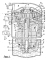
- compressor 10 comprises a cylindrical hermetic shell 12 which includes at the upper end thereof an end cap 14. End cap 14 is provided with a refrigerant discharge fitting 16 optionally having the usual discharge valve therein.
- affixed to the shell include a transversely extending partition 18 which is welded about its periphery at the same point that end cap 14 is welded to shell 12, a two-piece main bearing housing 20 which is affixed to shell 12 at a plurality of points in any desirable manner, and a suction gas inlet fitting 22 disposed in communication with the suction pressure zone of compressor 10 inside shell 12.
- a motor stator 24 is press fit into a frame 26 which is in turn press fit into shell 12.
- a crankshaft 28 having an eccentric crank pin 30 at the upper end thereof is rotatably journaled in a bearing 32 in main bearing housing 20 and a second bearing 34 in frame 26.
- Crankshaft 28 has at the lower end the usual relatively large diameter oil-pumping concentric bore 36 which communicates with a radially outwardly inclined smaller diameter bore 38 extending upwardly therefrom to the top of crankshaft 28.
- the lower portion of the interior shell 12 is filled with lubricating oil in the usual manner and concentric bore 36 at the bottom of crankshaft 28 is the primary pump acting in conjunction with bore 38, which acts as a secondary pump, to pump lubricating fluid to all the various portions of compressor 10 which require lubrication.
- Crankshaft 28 is rotatively driven by an electric motor including stator 24 having windings 40 passing therethrough, and a rotor 42 press fit on crankshaft 28 and having one or more counterweights 44.
- a motor protector 46 of the usual type, is provided in close proximity to motor windings 40 so that if the motor exceeds its normal temperature range motor protector 46 will de-energize the motor.
- main bearing housing 20 The upper surface of main bearing housing 20 is provided with an annular flat thrust bearing surface 48 on which is disposed an orbiting scroll member 50 comprising an end plate 52 having the usual spiral vane or wrap 54 on the upper surface thereof, an annular flat thrust surface 56 on the lower surface, and projecting downwardly therefrom a cylindrical hub 58 having a journal bearing 60 therein and in which is rotatively disposed a drive bushing 62 having an inner bore in which crank pin 30 is drivingly disposed.
- Crank pin 30 has a flat on one surface (not shown) which drivingly engages a flat surface in a portion of the inner bore of drive bushing 62 to provide a radially compliant driving arrangement, such as shown in assignee's U.S. Patent No. 4,877,382 , the disclosure of which is herein incorporated by reference.
- Non-orbiting scroll member 66 has a centrally disposed discharge passageway communicating with an upwardly open recess 72 which is in fluid communication via an opening 74 in partition 18 with a discharge muffler chamber 76 defined by end cap 14 and partition 18.
- a pressure relief valve is disposed between the discharge muffler chamber 76 and the interior of shell 12. The pressure relief valve will open at a specified differential pressure between the discharge and suction pressures to vent pressurized gas from the discharge muffler chamber 76.
- Non-orbiting scroll member 66 has in the upper surface thereof an annular recess 80 having parallel coaxial side walls in which is sealingly disposed for relative axial movement an annular floating seal 82 which serves to isolate the bottom of recess 80 from the presence of gas under suction and discharge pressure so that it can be placed in fluid communication with a source of intermediate fluid pressure by means of a passageway 84 (not shown).
- Non-orbiting scroll member 66 is thus axially biased against orbiting scroll member 50 by the forces created by discharge pressure acting on the central portion of scroll member 66 and those created by intermediate fluid pressure acting on the bottom of recess 80.
- This axial pressure biasing, as well as various techniques for supporting scroll member 66 for limited axial movement, are disclosed in much greater detail in assignee's aforesaid U.S. Patent No. 4,877,328 .
- Oldham coupling comprising a ring 86 having a first pair of keys 88 (one of which is shown) slidably disposed in diametrically opposed slots 90 (one of which is shown) in scroll member 66 and a second pair of keys (not shown) slidably disposed in diametrically opposed slots in scroll member 50.
- seal 82 is of a coaxial sandwiched construction and comprises an annular base plate 100 having a plurality of equally spaced upstanding integral projections 102. Disposed on plate 100 is an annular gasket 106 having a plurality of equally spaced holes which receive projections 102. On top of gasket 106 is disposed an upper seal plate 110 having a plurality of equally spaced holes which receive projections 102. Seal plate 110 has disposed about the inner periphery thereof an upwardly projecting planar sealing lip 116. The assembly is secured together by swaging the ends of each of the projections 102, as indicated at 118.
- the overall seal assembly therefore provided three distinct seals; namely, an inside diameter seal at 124, an outside diameter seal at 128 and a top seal at 130.
- Seal 124 is between the inner periphery of gasket 106 and the inside wall of recess 80. Seal 124 isolates fluid under intermediate pressure in the bottom of recess 80 from fluid under discharge pressure in recess 72.
- Seal 128 is between the outer periphery of gasket 106 and the outer wall of recess 80, and isolates fluid under intermediate pressure in the bottom of recess 80 from fluid at suction pressure within shell 10.
- Seal 130 is between sealing lip 116 and an annular wear ring surrounding opening 74 in partition 18, and isolates fluid at suction pressure from fluid at discharge pressure across the top of the seal assembly.
- the details of the construction of seal 82 is similar to that described in U.S. Patent No. 5,156,539 , the disclosure of which is hereby incorporated herein by reference.
- the compressor is preferably the "low side" type in which suction gas entering gas inlet fitting 22 is allowed, in part, to escape into shell 12 and assist in cooling the motor. So long as there is an adequate flow of returning suction gas the motor will remain within desired temperature limits. When this flow drops significantly, however, the loss of cooling will eventually cause motor protector 46 to trip and shut the machine down.
- scroll compressor 10 is typical of such scroll-type refrigeration compressors.
- suction gas directed to the lower chamber via suction gas inlet fitting 22 is drawn into the moving fluid pockets as orbiting scroll member 50 orbits with respect to non-orbiting scroll member 66.
- this suction gas is compressed and subsequently discharged into muffler chamber 76 via upwardly open recess 72 in non-orbiting scroll member 66 and discharge opening 74 in partition 18.
- Compressed refrigerant is then supplied to the refrigeration system via discharge fitting 16.
- compressor 10 is provided with a capacity modulation system.
- the capacity modulation system allows the compressor to operate at the capacity required to meet the requirements of the system.
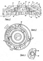
- the capacity modulation system includes an annular valving ring 150 movably mounted on non-orbiting scroll member 66, an actuating assembly 152 supported within shell 12 and a control system 154 for controlling operation of the actuating assembly.
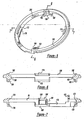
- valving ring 150 comprises a generally circular shaped main body portion 156 having a pair of substantially diametrically opposed radially inwardly extending protrusions 158 and 160 provided thereon of substantially identical predetermined axial and circumferential dimensions. Suitable substantially identical circumferentially extending guide surfaces 162, 164 and 166, 168 are provided adjacent axially opposite sides of protrusions 158 and 160, respectively. Additionally, two pairs of substantially identical circumferentially extending axially spaced guide surfaces 170, 172 an 174, 176 are provided on main body 156 being positioned in substantially diametrically opposed relationship to each other and spaced circumferentially approximately 90° from respective protrusions 158 and 160.
- guide surfaces 172 and 174 project radially inwardly slightly more from main body 156 as do guide surfaces 162 and 166.
- guide surfaces 172, 174 and 162, 166 are all axially aligned and lie along the periphery of a circle of a radius slightly less than the radius of main body 156.
- guide surfaces 170 and 176 project radially inwardly slightly more from main body 156 as do guide surfaces 164 and 168 with which they are preferably axially aligned.
- Main body 156 also includes a circumferentially extending stepped portion 178 which includes an axially extending circumferentially facing stop surface 180 at one end. Step portion 178 is positioned between protrusion 160 and guide surfaces 170, 172.
- a pin member 182 is also provided extending axially upwardly adjacent one end of stepped portion 178.
- Valving ring 150 may be fabricated from a suitable metal such as aluminum or alternatively may be formed from a suitable polymeric composition and pin 182 may be either pressed into a suitable opening provided therein or integrally formed therewith.
- valving ring 150 is designed to be movably mounted on non-orbiting scroll member 66.
- non-orbiting scroll member 66 includes a radially outwardly facing cylindrical sidewall portion 184 thereon having an annular groove 186 formed therein adjacent the upper end thereof.
- a pair of diametrically opposed substantially identical radially inwardly extending notches 188 and 190 are provided in non-orbiting scroll member 66 each opening into groove 186 as best seen with reference to Figure 3 .
- Notches 188 and 190 have a circumferentially extending dimension slightly larger than the circumferential extent of protrusions 158 and 160 on valving ring 150.
- Groove 186 is sized to movably accommodate protrusions 158 and 160 when valving ring is assembled thereto and notches 188 and 190 are sized to enable protrusions 158 and 160 to be moved into groove 186. Additionally, cylindrical portion 184 will have a diameter such that guide surfaces 162, 164, 166, 168, 170, 172, 174 and 176 will slidingly support rotary movement of valving ring 150 with respect to non-orbiting scroll member 66.
- Non-orbiting scroll member 66 also includes a pair of generally diametrically opposed radially extending passages 192 and 194 opening into the inner surface of groove 186 and extending generally radially inwardly through the end plate of non-orbiting scroll member 66.
- An axially extending passage 196 places the inner end of passage 192 in fluid communication with annular recess 80 while a second axially extending passage 198 places the inner end of passage 194 in fluid communication with annular recess 80.
- actuating assembly 152 includes a piston and cylinder assembly 200 and a return spring assembly 202.
- Piston and cylinder assembly 200 includes a housing 204 having a bore defining a cylinder 206 extending inwardly from one end thereof and within which a piston 208 is movably disposed.
- An outer end 210 of piston 208 projects axially outwardly from one end of housing 204 and includes an elongated or oval-shaped opening 212 therein adapted to receive pin 182 forming a part of valving ring 150.
- Elongated or oval opening 212 is designed to accommodate the arcuate movement of pin 182 relative to the linear movement of piston end 210 during operation.
- a depending portion 214 of housing 204 has secured thereto a suitably sized mounting flange 216 which is adapted to enable housing 204 to be secured to a suitable flange member 218 by bolts 220.
- Flange 218 is in turn suitably supported within outer shell 12 such as by bearing housing 20.
- a passage 222 is provided in depending portion 214 extending upwardly from the lower end thereof and opening into a laterally extending passage 224 which in turn opens into the inner end of cylinder 206.
- a second laterally extending passage 226 provided in depending portion 214 opens outwardly through the sidewall thereof and communicates at its inner end with passage 222.
- a second relatively small laterally extending passage 228 extends from fluid passage 222 in the opposite direction of fluid passage 224 and opens outwardly through an end wall 230 of housing 204.
- a pin member 232 is provided upstanding from housing 204 to which is connected one end of a return spring 234 the other end of which is connected to an extended portion of pin 182.
- Return spring 234 will be of such a length and strength as to urge ring 150 and piston 208 into the position shown in Figure 9 when cylinder 206 is fully vented via passage 228.
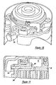
- control system 154 includes a valve body 236 having a radially outwardly extending flange 238 including a conical surface 240 on one side thereof.
- Valve body 236 is inserted into an opening 242 in outer shell 12 and positioned with conical surface 240 abutting the peripheral edge of opening 242 and then welded to shell 12 with a cylindrical portion 244 projecting outwardly therefrom.
- Cylindrical portion 244 of valve body 236 includes an enlarged diameter threaded bore 246 extending axially inwardly and opening into a recess area 248.
- Valve body 236 includes a housing 250 having a first passage 252 extending downwardly from a substantially flat upper surface 254 and intersecting a second laterally extending passage 256 which opens outwardly into the area of opening 242 in shell 12.
- a third passage 258 also extends downwardly from surface 254 and intersects a fourth laterally extending passage 260 which also opens outwardly into recessed area 248 provided in the end portion of body 236.
- a manifold 262 is sealingly secured to surface 254 by means of suitable fasteners and includes fittings for connection of one end of each of fluid lines 264 and 266 so as to place them in sealed fluid communication with respective passages 258 and 252.
- a solenoid coil assembly 268 is designed to be sealingly secured to valve body 236 and includes an elongated tubular member 270 having a threaded fitting 272 sealingly secured to the open end thereof. Threaded fitting 272 is adapted to be threadedly received within bore 246 and sealed thereto by means of an O-ring 274.
- a plunger 276 is movably disposed within tubular member 270 and is biased outwardly therefrom by a spring 278 which bears against a closed end of tubular member 270.
- a valve member 280 is provided on the outer end of plunger 276 and cooperates with a valve seat 282 to selectively close off passage 256.
- a solenoid coil 284 is positioned on tubular member 270 and secured thereto by means of a nut threaded on the outer end of tubular member 270.
- an axially extending passage 286 extends downwardly from open recess 72 and connects to a generally radially extending passage 288 in non-orbiting scroll member 66.
- Passage 288 extends radially and opens outwardly through the circumferential sidewall of non-orbiting scroll 66 as best seen with reference to Figure 11 .
- the other end of fluid line 264 is sealingly connected to passage 288 whereby a supply of compressed fluid may be supplied from open recess 72 to valve body 236.
- a circumferentially elongated opening 290 is provided in valving ring 150 suitably positioned so as to enable fluid line 264 to pass therethrough while accommodating the rotational movement of ring 150 with respect to non-orbiting scroll member 66.
- fluid line 266 extends from valve body 236 and is connected to passage 226 provided in depending portion 214 of housing 204.
- Valving ring 150 may be easily assembled to non-orbiting scroll member 66 by merely aligning protrusions 158 and 160 with respective notches 188 and 190 and moving protrusions 158 and 160 into annular groove 186. Thereafter valving ring 150 is rotated into the desired position with the axially upper and lower surfaces of protrusions 158 and 160 cooperating with guide surfaces 162, 164, 166, 168, 170, 172, 174 and 176 to movably support valving ring 150 on non-orbiting scroll member 66. Thereafter, housing 204 of actuating assembly 152 may be positioned on mounting flange 218 with piston end 210 receiving pin 182. One end of spring 234 may then be connected to pin 232. thereafter, the other end of spring 234 may be connected to pin 182 thus completing the assembly process.
- non-orbiting scroll member 66 While non-orbiting scroll member 66 is typically secured to main bearing housing 20 by suitable bolts 292 prior to assembly of valving ring 150, it may in some cases be preferable to assemble this continuous capacity modulation component to non-orbiting scroll member 66 prior to assembly of non-orbiting scroll member 66 to main bearing housing 20. This may be easily accomplished by merely providing a plurality of suitably positioned arcuate cutouts 294 along the periphery of valving ring 150 as shown in Figure 4 . these cutouts will afford access to securing bolts 292 with valving ring assembled to non-orbiting scroll member 66.
- control module 298 will operate in response to a signal from sensors 296 to energize solenoid coil 284 of solenoid assembly 268 thereby causing plunger 276 to be moved out of engagement with valve seat 282 thereby placing passages 256 and 260 in fluid communication. Pressurized fluid at substantially discharge pressure will then be allowed to flow from open recess 72 to cylinder 206 via passages 286, 288 fluid line 264, passages 258, 260, 256, 252 fluid line 266 and passages 226, 222 and 224.
- sensors 296 When the load conditions change to the point that the full capacity of compressor 10 is not required, sensors 296 will provide a signal indicate thereof to controller 298 which in turn will deenergize coil 284 of solenoid assembly 268. Plunger 276 will then move outwardly from tubular member 270 under the biasing action of spring 278 thereby moving valve member 280 into sealing engagement with seat 282 thus closing off passage 256 and the flow of pressurized fluid therethrough. It is noted that recessed area 248 will be in continuous fluid communication with open recess 72 and hence continuously subject to discharge pressure. This discharge pressure will aid in biasing valve member 280 into fluid tight sealing engagement with valve seat 282 as well as retaining same in such relationship.
- the pressurized gas contained in cylinder 206 will bleed back into the suction zone of compressor 10 via vent passage 228 thereby enabling spring 234 to rotate valving ring 150 back to a position in which passages 192 and 194 are no longer closed off by protrusions 158 and 160.
- Spring 234 will also move piston 208 inwardly with respect to cylinder 206. In this position, the intermediate pressure within annular recess 80 will be exhausted or vented through passages 192 and 194.
- the venting of the intermediate pressurized fluid removes the biasing force urging non-orbiting scroll member 66 into sealing engagement with orbiting scroll member 50 to create a leak between the discharge pressure zone and the suction pressure zone. This leak causes the capacity of compression 10 to move to zero capacity.
- a spring 300 urges floating seal 82 upwards and maintains the sealing relationship at top seal 130.
- valving ring 150 may be moved between the modulated position and the unmodulated position will be directly related to the relative size of vent passage 228 and the supply lines.
- passage 228 is continuously open to the suction pressure zone of compressor 10
- coil 284 of solenoid assembly 268 when coil 284 of solenoid assembly 268 is energized a portion of the pressurized fluid flowing from open recess 72 will be continuously vented to suction pressure.
- the volume of this fluid will be controlled by the relative sizing of passage 228.
- passage 228 is reduced in size, the time required to vent cylinder 206 will increase thus increasing the time required to switch from reduced capacity to full capacity.
- FIG. 13 shows a modified valve body 236' incorporating a vent passage 312 which will operate to continuously vent passage 252" to suction pressure and hence allow cylinder 206 to vent to suction via line 266.
- Figure 14 shows a modified piston and cylinder assembly 200' in which vent passage 228 has been deleted.
- the operation and function of valve body 236' and piston cylinder assembly 200' will otherwise be substantially identical to that disclosed above. Accordingly, corresponding portions of valve bodies 236 and 236', piston and cylinder assemblies 200 and 200' are substantially identical and have each been indicated by the same reference numbers.
- valve body 314 is secured to shell 12 in the same manner as described above and includes an elongated central bore 316 within which is movably disposed a spool valve 318.
- Spool valve 318 extends outwardly through shell 12 into solenoid coil 320 and is adapted to be moved longitudinally outwardly from valve body 314 upon energization of solenoid coil 320.
- a coil spring 322 operates to bias spool valve 318 into valve body 314 when coil 320 is not energized.
- Spool valve 318 includes an elongated axially extending central passage 324 the inner end of which is plugged via plug 326.
- Three groups of generally radially extending axially spaced passages 328, 330, 332 are provided, each group consisting of one or more such passages which extend outwardly from central passages 324 with each group opening into axially spaced annular grooves 334, 336 and 338 respectively.
- Valve body 314 in turn is provided with a first high pressure supply passage 340 which opens into bore 316 and is adapted to be connected to fluid line 264 to supply compressed fluid to valve body 314.
- a second passage 342 in valve body also opens into bore 316 and is adapted to be connected to fluid line 266 at its outer end to place bore 316 in fluid communication with cylinder 206.
- a vent passage 344 is also provided in valve body 314 having one end opening into bore 316 with the other end opening into the suction pressure zone of shell 12.
- spool valve 318 In operation, when solenoid coil is deenergized, spool valve 318 will be in a position such that annular groove 334 will be in open communication with passage 342 and annular groove 338 will be in open communication with vent passage 344 thereby continuously venting cylinder 206. At this time, spool valve 318 will be positioned such that annular seals will lie on axially opposite sides of passage 340 thereby preventing flow of compressed fluid from open recess 72. When it is desired to actuate the capacity modulation system to increase the capacity of compressor 10, solenoid coil 320 will be energized thereby causing spool valve 318 to move outwardly from valve body 314.
- annular groove 338 moving out of fluid communication with vent passage 344 while annular groove 336 is moved into open communication with high pressure supply passage 340.
- pressurized fluid from passage 340 will be supplied to cylinder 206 via passages 330 and 328 in spool valve 318.
- Additional suitable axially spaced annular seals will also be provided on spool valve 318 to ensure a sealing relationship between spool valve 318 and bore 316.
- the capacity modulation system can control the capacity of compressor 10 to be 100% capacity or it can be zero capacity. Also, by controlling the capacity modulation system detailed above using a pulsed width modulation system, the capacity of compressor 10 can be set at any point between zero capacity and 100% capacity to provide complete control of compressor 10. For example, pulsed width modulation control for solenoid coil assembly 268 will provide the capacity control for compressor 10 anywhere between zero percent and 100%.
- FIG. 16 a scroll compressor 10' is illustrated.
- Compressor 10' is the same as compressor 10 except that transversely extending partition 18 has been eliminated and floating seal 82 defines top seal 130, which is now between sealing lip 116 and annular wear ring 132 disposed on end cap 14.
- top seal 130 isolates fluid at suction pressure from fluid at discharge pressure across the top of the seal assembly 82 also.
- Discharge fitting 16' is disposed on end cap 14 over an opening 74' located within end cap 14 to define a direct discharge compressor.
- An appropriate fitting 76' secures discharge fitting 16' to end cap 14.
- compressor 10' The remaining details for compressor 10' are the same as that described above for compressor 10 and, thus, they will not be repeated.
- the function, operation and advantages described above for compress 10 are the same for compressor 10'.
- a compressor 410 which comprises generally cylindrical hermetic shell 12 having welded at the upper end thereof end cap 14.
- End cap 14 is provided with refrigerant discharge fitting 16 which may have the usual discharge valve therein (not shown).
- Other major elements affixed to the shell include inlet fitting 22, transversely extending partition 18 which is welded about its periphery at the same point that end cap 14 is welded to shell 12, two piece main bearing housing 20 and frame 26.
- Frame 26 locates and supports within shell 12 two piece main bearing housing 20 and motor stator 24.
- Drive shaft or crankshaft 28 having eccentric crank pin 30 at the upper end thereof is rotatably journaled in bearing 32 in main bearing housing 20 and second bearing 34 in frame 26.
- Crankshaft 28 has at the lower end relatively large diameter concentric bore 36 which communicates with radially outwardly inclined smaller diameter bore 38 extending upwardly therefrom to the top of crankshaft 28.
- the lower portion of the interior shell 12 is filled with lubricating oil, and bore 36 acts as a pump to pump lubricating fluid up crankshaft 28 and into bore 38 and ultimately to all of the various portions of the compressor which require lubrication.
- crankshaft 28 is rotatively driven by the electric motor inciuding motor stator 24 windings 40 passing therethrough and motor rotor 42 press fitted on crankshaft 28 and having upper and lower counterweights.
- the upper surface of two piece main bearing housing 20 is provided with flat thrust bearing surface 48 on which is disposed orbiting scroll 50 having the usual spiral vane or wrap 54 on the upper surface thereof.
- orbiting scroll 50 Projecting downwardly from the lower surface of orbiting scroll 50 is cylindrical hub 58 having journal bearing 60 therein and in which is rotatively disposed drive bushing 62 having an inner bore in which crank pin 30 is drivingly disposed.
- Crank pin 30 has a flat on one surface which drivingly engages a flat surface (not shown) formed in a portion of the inner bore of drive bushing 62 to provide a radially compliant driving arrangement.
- An Oldham coupling is also provided positioned between orbiting scroll 50 and bearing housing 20. The Oldham coupling is keyed to orbiting scroll 50 and a non-orbiting scroll 466 to prevent rotational movement of orbiting scroll member 50.
- Non-orbiting scroll member 466 is also provided having wrap 64 positioned in meshing engagement with wrap 54 of orbiting scroll 50.
- Non-orbiting scroll 466 has a centrally disposed discharge passage which communicates with upwardly open recess 72 which in turn is in fluid communication via opening 74 in partition 18 with discharge muffler chamber 76 defined by end cap 14 and partition 18.
- Non-orbiting scroll member 466 has in the upper surface thereof annular recess 80 having parallel coaxial sidewalls in which is sealingly disposed for relative axial movement annular floating seal 82 which serves to isolate the bottom of recess 80 from the presence of gas under suction pressure and gas under discharge pressure so that it can be placed in fluid communication with a source of gas at an intermediate fluid pressure by means of passageway 84.
- Non-orbiting scroll member 466 is thus axially biased against orbiting scroll member 50 to enhance wrap tip sealing by the forces created by discharge pressure acting on the central portion of scroll member 466 and those created by intermediate fluid pressure acting on the bottom of recess 80. Discharge gas is also sealed from gas at suction pressure in shell 12 by means of a seal acting against annular wear ring 132 attached to partition 18. Non-orbiting scroll member 466 is designed to be mounted to bearing housing 20 in a suitable manner which will provide limited axial (and no rotational) movement of non-orbiting scroll member 466.
- Compressor 410 is preferably of the "low side" type in which suction gas entering via fitting 22 is allowed, in part, to escape into the shell and assist in cooling the motor. So long as there is an adequate flow of returning suction gas the motor will remain within desired temperature limits. When this flow ceases, however, the loss of cooling will cause a motor protector to trip and shut the machine down.
- the valve of the present invention operates to allow gas at intermediate pressure to flow to an area of suction pressure which then allows discharge pressure to dump to suction pressure. By working with gas at intermediate pressure rather than directly with gas at discharge pressure, the size complexity and cost of the valve can be significantly reduced.
- the valve is operated by an internal solenoid, and in another embodiment, the valve is operated by an external solenoid. It is believed that all embodiments of the present invention are fully applicable to any type of scroll compressor.
- FIG. 17 makes use of the dual pressure balancing scheme described above to axially balance non-orbiting scroll member 466 with floating seal 82 being used to separate the discharge gas pressure from the suction gas pressure.
- a solenoid valve 412 is operable to open and close a passageway 414 located within non-orbiting scroll 466. Passageway 414 extends from the bottom of recess 80 which is at intermediate pressure during operation of compressor 410 to the area of compressor 410 which contains suction gas at suction gas pressure.
- control module 298 In operation, when system operating conditions as sensed by one or more sensors 296 indicate that full capacity of compressor 410 is required, control module 298 will operate in response to a signal from sensors 296 to energize solenoid valve 412 thereby prohibiting passageway 414 from communicating with the suction area of compressor 410, and compressor 410 will operate at full capacity.
- sensors 296 When the load conditions change to the point that the full capacity of compressor 410 is not required, sensors 296 will provide a signal indicative thereof to controller 298 which in turn will deenergize solenoid valve 412 thereby placing passageway 414 in communication with the suction area of compressor 410.
- the intermediate pressure within annular recess 80 will be exhausted or vented through passageway 414 to remove the biasing force urging non-orbiting scroll member 466 into sealing engagement with orbiting scroll member 50.
- Spring 300 urges floating seal 82 upwards and maintains the sealing relationship at top seal 130.
- Non-orbiting scroll 466 will be biased away from orbiting scroll member 50 creating a leak between the discharge pressure zone and the suction pressure zone. The leak causes the capacity of compressor 410 to move to zero.
- the capacity modulation system can control the capacity of compressor 410 to be 100% capacity or it can be zero. Also, by controlling solenoid valve 412 using a pulsed width modulation system.
- the capacity of compressor 410 can be set at any point between zero capacity and 100% capacity to provide complete control of compressor 410. Stated differently, pulsed width modulation control of solenoid valve 412 will provide the capacity control for compressor 410 anywhere between 0% and 100% capacity.
- Compressor 410' is the same as compressor 410 except that solenoid valve 412 has been replaced by solenoid valve 412'.
- Solenoid valve 412' is located outside of shell 12 as opposed to solenoid valve 412 which is located within shell 12.
- a fluid pipe 422 extends through a fitting 424 attached to shell 12 to place solenoid valve 412' in communication with recess 80.
- a fluid pipe 426 extends between solenoid valve 412' and suction inlet fitting 22 to place solenoid valve 412' in communication with the suction pressure zone of compressor 410.
- the function and operation of compressor 410' and solenoid valve 412' are the same as described above for compressor 410 and solenoid valve 412.
- Compressor 410" is the same as compressor 410 except that transversely extending partition 18 has been eliminated and seal 82 defines top seal 130, which is now between sealing lip 116 and annular wear ring 132 disposed on end cap 14.
- top seal 130 isolates fluid at suction pressure from fluid at discharge pressure across the top of seal assembly 82 also.
- Discharge fitting 16' is disposed within end cap 14 through an opening 74" located within end cap 14 to define a direct discharge compressor.
- compressor 410 The remaining details for compressor 410" are the same as that described above for compressor 410 and, thus, they will not be repeated.
- the function, operation and advantages described above for compress 410 are the same for compressor 410".
- Compressor 410"' is the same as compressor 410' except that transversely extending partition 18 has been eliminated and seal 82 defines top seal 130, which is now between sealing lip 116 and annular wear ring 132 disposed on end cap 14.
- top seal 130 isolates fluid at suction pressure from fluid at discharge pressure across the top of seal assembly 83 also.
- Discharge fitting 16' is disposed within end cap 14 through an opening 74" located within end cap 14 to define a direct discharge compressor.
- compressor 410' The remaining details for compressor 410'" are the same as that described above for compressor 410' and, thus, they will not be repeated.
- the function, operation and advantages described above for compress 410' and 410 are the same for compressor 410"'.
- Compressor 510 seals fluid pressure between an end cap 514 and a non-orbiting scroll member 566.
- a discharge fitting 516 and a suction fitting 522 are secured to end cap 514 to provide for a direct discharge scroll compressor and for providing for the return of the decompressed gas to compressor 510.
- Non-orbiting scroll member 566 is designed to replace non-orbiting scroll member 66 or any other of the non-orbiting scroll members described above.
- a partition between the suction pressure zone and the discharge pressure zone of compressor 510 has been eliminated due to a sealing system 520 being disposed between end cap 514 and non-orbiting scroll member 566.
- Non-orbiting scroll member 566 includes scroll wrap 64 and it defines an annular recess 580, an outer seal groove 582 and an inner seal groove 584.
- a passage 586 interconnects annular recess 580 with outer seal groove 582.
- Annular chamber 580 is located between outer seal groove 582 and inner seal groove 584 and it is provided compressed fluid through a fluid passage 84 which opens to a fluid pocket defined by non-orbiting scroll wrap 64 of non-orbiting scroll member 566 and orbiting scroll wrap 54 of orbiting scroll member 50.
- the pressurized fluid provided through fluid passage 84 is at a pressure which is intermediate or in between the suction pressure and the discharge pressure of the compressor.
- the fluid pressure within annular chamber 580 biases non-orbiting scroll member 566 towards orbiting scroll member 50 to enhance the tip sealing characteristics between the two scroll members.
- a flip seal 590 is disposed within outer seal groove 582 and a flip seal 592 is disposed within inner seal groove 584.
- Flip seal 590 sealing engages non-orbiting scroll member 566 and end cap 514 to isolate annular recesses 580 from suction pressure.
- Flip seal 592 sealingly engages non-orbiting scroll member 566 and end cap 514 to isolate annular recesses 580 from discharge pressure.
- compressor 510 makes use of the dual pressure balancing scheme described above to axially balance non-orbiting scroll member 566 without the use of a floating seal to separate the discharge gas pressure from the suction gas pressure.
- a solenoid valve 532 is operable to open and close a passageway 534 located within non-orbiting scroll member 566. Passageway 534 extends from the bottom of annular chamber 580 which is at intermediate pressure during operation of compressor 510 to an area of compressor 510 which contains suction gas at suction gas pressure.
- control module 298 In operation, when system operating conditions as sensed by one or more sensors 296 indicate that full capacity of compressor 510 is required, control module 298 will operate in response to a signal from sensors 296 to energize solenoid valve 532 thereby prohibiting passageway 534 from communicating with the suction area of compressor 510 and compressor 510 will operate at full capacity.
- sensors 296 When the load conditions change to the point that full capacity of compressor 510 is not required, sensors 296 will provide a signal indicative thereof to controller 298 which in turn will deenergize solenoid valve 532 thereby placing passageway 534 in communication with the suction area of compressor 510.
- the intermediate pressure within annular chamber 580 will be exhausted or vented through passageway 534 to remove the biasing force urging non-orbiting scroll member 566 into sealing engagement with orbiting scroll member 50.
- Non-orbiting scroll member 566 will be biased away from orbiting scroll member 50 creating a leak between the discharge pressure zone and the suction pressure zone. This leak causes the capacity of compressor 510 to move to zero.
- the capacity modulation system can control the capacity of compressor 510 to be 100% capacity or it can be zero. Also, by controlling solenoid valve 532 using a pulsed width modulation system, the capacity of compressor 510 can be set at any point between zero capacity and 100% capacity to provide complete control of compressor 510. Stated differently, pulsed width modulation control of solenoid valve 532 will provide the capacity control for compressor 510 anywhere between 0% and 100% capacity.
- Compressor 510' is the same as compressor 510 except that solenoid valve 532 has been replaced by solenoid valve 532'.
- Solenoid valve 532' is located outside of shell 12 as opposed to solenoid valve 532 which is located within shell 12.
- a fluid pipe 542 extends through a fitting 544 attached to end cap 514 to place solenoid valve 532' in communication with annular chamber 580.
- a fluid pipe 546 extends between solenoid valve 532' and suction inlet fitting 522 or is otherwise connected to the suction chamber of compressor 510 to place solenoid valve 532' in communication with the suction pressure zone of compressor 510.
- the function and operation of compressor 510' and solenoid valve 532' are the same as described above for compressor 510 and solenoid valve 532.
- Compressor 510 is the same as compressor 510 except that transversely extending partition 18 has been added to define discharge muffler chamber 76 for compressor 510".
- Flip seal 590 sealingly engages non-orbiting scroll member 566 and partition 18 to isolate annular recess 580 from suction pressure; while flip seal 592 sealingly engages non-orbiting scroll member 566 and partition 18 to isolate annular recess 580 from discharge pressure.
- Discharge fitting 16 (not shown in Figure 23 ) is secured to end cap 14 similar to that illustrated in Figure 1 .
- compressor 510 The remaining details for compressor 510" are the same as that described above for compressor 510 and, thus, they will not be repeated here.
- the function, operation and advantages described above for compressor 510 are the same for compressor 510".
- Compressor 510"' is the same as compressor 510' except that transversely extending partition 18 has been added to define discharge muffler chamber 76 for compressor 510'" similar to that described above for compressor 510".
- Flip seal 590 sealingly engages non-orbiting scroll member 566 and partition 18 to isolate annular recess 580 from suction pressure; while flip seal 592 sealingly engages non-orbiting scroll member 566 and partition 18 to isolate annular recess 580 from discharge pressure.
- Discharge fitting 16 (not shown in Figure 24 ) is secured to end cap 14 similar to that illustrated in Figure 1 .
- compressor 510"' The remaining details for compressor 510"' are the same as that described above for compressors 510' and 510 and, thus, they will not be repeated here.
- the function, operation and advantages described above for compressors 510' and 510 are the same for compressor 510"'.
Landscapes
- Engineering & Computer Science (AREA)
- Mechanical Engineering (AREA)
- General Engineering & Computer Science (AREA)
- Physics & Mathematics (AREA)
- Fluid Mechanics (AREA)
- Rotary Pumps (AREA)
- Applications Or Details Of Rotary Compressors (AREA)
Claims (28)
- Machine à volutes (10), comprenant :un premier élément de volute (66) comportant un premier enroulement en spirale (64) faisant saillie vers l'extérieur à partir d'une première plaque d'extrémité, ledit premier élément de volute (66) définissant une cavité (80) ;un deuxième élément de volute (50) comportant un deuxième enroulement de volute en spirale (54) faisant saillie vers l'extérieur à partir d'une deuxième plaque d'extrémité (52), ledit deuxième enroulement en spirale (54) étant mutuellement engrené avec ledit premier enroulement en spirale (64), lesdits éléments de volute (50, 66) étant montés pour un mouvement axial limité l'un par rapport à l'autre, lesdits éléments de volute (50, 66) étant sollicités l'un vers l'autre par un fluide sous pression disposé à l'intérieur de ladite cavité (80) ;un élément d'entraînement (28) pour amener lesdits éléments de volute (50, 66) à orbiter l'un par rapport à l'autre, grâce à quoi lesdits enroulements en spirale (54, 64) créeront des poches de volume changeant progressivement entre une zone de pression d'aspiration à une pression d'aspiration et une zone de pression de décharge à une pression de décharge ;un joint d'étanchéité (82) disposé à l'intérieur de ladite cavité (80), ledit joint d'étanchéité (82) étant sollicité vers un composant (18) de ladite machine à volutes (10) au moins par ledit fluide sous pression de façon à fermer un premier trajet de fuite entre ledit joint d'étanchéité (82) et ledit composant (18), s'étendant depuis ladite zone de pression de décharge jusqu'à ladite zone de pression d'aspiration ; etun ensemble de vanne (150, 268) pour relâcher ledit fluide sous pression, grâce à quoi lesdits éléments de volute (50, 66) se déplaceront axialement l'un par rapport à l'autre de façon à ouvrir un deuxième trajet de fuite entre ladite zone de pression d'aspiration et ladite zone de pression de décharge, afin de moduler la sortie de compresseur (10),caractérisée en ce que :ledit joint d'étanchéité (82) est sollicité vers ledit composant (18) lorsque ledit deuxième trajet de fuite est ouvert.
- Machine à volutes (10) selon la revendication 1, dans laquelle ledit fluide sous pression est relâché vers ladite zone de pression d'aspiration de ladite machine à volutes.
- Machine à volutes (10) selon la revendication 1 ou 2, dans laquelle ledit ensemble de vanne est une électrovanne (412, 412', 532, 532').
- Machine à volutes (10) selon la revendication 3, dans laquelle ladite électrovanne (412, 412', 532, 532') est actionnée d'une manière pulsée, de façon à moduler la capacité de ladite machine à volutes.
- Machine à volutes (10) selon l'une quelconque des revendications précédentes, dans laquelle ledit fluide sous pression est à une pression entre ladite pression d'aspiration et ladite pression de décharge.
- Machine à volutes (10) selon l'une quelconque des revendications précédentes, dans laquelle ladite machine à volutes comprend de plus une enveloppe (12), lesdits premier et deuxième éléments de volute (66, 50) étant disposés à l'intérieur de ladite enveloppe (12).
- Machine à volutes (10) selon la revendication 6, dans laquelle ledit ensemble de vanne est disposé à l'extérieur de ladite enveloppe (12).
- Machine à volutes (10) selon la revendication 6 ou 7, dans laquelle ledit ensemble de vanne est fixé à ladite enveloppe (12).
- Machine à volutes (10) selon la revendication 7, dans laquelle ladite machine à volutes comprend de plus un orifice d'entrée de gaz d'aspiration (22), ledit ensemble de vanne étant fixé audit orifice d'entrée de gaz d'aspiration (22).
- Machine à volutes (10) selon la revendication 7, comprenant de plus un tube s'étendant à travers ladite enveloppe (12), ledit tube mettant ladite cavité (80) et ledit ensemble de vanne en communication fluidique l'un avec l'autre.
- Machine à volutes (10) selon la revendication 10, dans laquelle ledit premier élément de volute (66) définit un passage entre ladite cavité (80) et ledit tube.
- Machine à volutes (10) selon la revendication 6, dans laquelle ledit ensemble de vanne est disposé à l'intérieur de ladite enveloppe (12).
- Machine à volutes (10) selon la revendication 12, dans laquelle ledit ensemble de vanne est fixé audit premier élément de volute (66).
- Machine à volutes (10) selon la revendication 13, dans laquelle ledit premier élément de volute (66) définit un passage entre ladite cavité et ledit ensemble de vanne.
- Machine à volutes (10) selon l'une quelconque des revendications précédentes, dans laquelle ledit ensemble de vanne comprend une bague (150) disposée de façon à pouvoir tourner sur ledit premier élément de volute (66).
- Machine à volutes (10) selon la revendication 15, comprenant de plus un actionneur linéaire (200) pour faire tourner ladite bague (150).
- Machine à volutes (10) selon la revendication 15, comprenant de plus un élément de vanne pour faire tourner ladite bague (150).
- Machine à volutes (10) selon la revendication 17, dans laquelle ledit élément de vanne est une électrovanne.
- Machine à volutes (10) selon la revendication 18, dans laquelle ladite électrovanne (412, 412', 532, 532') est actionnée d'une manière pulsée, de façon à moduler la capacité de la machine à volutes (10).
- Machine à volutes (10) selon l'une quelconque des revendications précédentes, dans laquelle ledit joint d'étanchéité comprend un joint à lèvre d'étanchéité (116) en prise avec ledit premier élément de volute (66).
- Machine à volutes (10) selon l'une quelconque des revendications 1 à 19, comprenant de plus une enveloppe (12), lesdits premier et deuxième éléments de volute (66, 50) étant disposés à l'intérieur de ladite enveloppe (12), ledit joint d'étanchéité comprenant un joint à lèvre d'étanchéité (116) en prise avec ladite enveloppe (12).
- Machine à volutes (10) selon la revendication 21, dans laquelle ladite enveloppe (12) comprend un capuchon d'extrémité (14, 514), ledit joint à lèvre d'étanchéité (116) étant en prise avec ledit capuchon d'extrémité (14, 514).
- Machine à volutes (10) selon l'une quelconque des revendications 1 à 19, comprenant de plus une séparation (18) séparant ladite zone de pression d'aspiration de ladite zone de pression de décharge, et ledit joint d'étanchéité (82) étant un joint à lèvre d'étanchéité (116) en prise avec ladite séparation (18).
- Machine à volutes (10) selon l'une quelconque des revendications précédentes, dans laquelle ledit composant est une enveloppe (10), lesdits premier et deuxième éléments de volute (66, 50) étant disposés à l'intérieur de ladite enveloppe (12).
- Machine à volutes (10) selon la revendication 24, dans laquelle ladite enveloppe (12) comprend un capuchon d'extrémité (14, 514), ledit composant étant ledit capuchon d'extrémité (14, 514) de ladite enveloppe (12).
- Machine à volutes (10) selon l'une quelconque des revendications 1 à 22, dans laquelle ledit composant est une séparation (18) séparant ladite zone de pression d'aspiration de ladite zone de pression de décharge.
- Machine à volutes (10) selon l'une quelconque des revendications précédentes, dans laquelle ledit joint d'étanchéité comprend :un premier joint à lèvre d'étanchéité (116) disposé entre ledit premier élément de volute (66) et ledit composant de ladite machine à volutes (10), ledit premier joint à lèvre d'étanchéité (116) isolant ladite cavité (80) vis-à-vis de ladite zone de pression de décharge ; etun deuxième joint à lèvre d'étanchéité (116) disposé entre ledit premier élément de volute (66) et ledit composant de ladite machine à volutes (10), ledit deuxième joint à lèvre d'étanchéité isolant ladite cavité (80) vis-à-vis de ladite zone de pression d'aspiration.
- Machine à volutes (10) selon l'une quelconque des revendications précédentes, comprenant de plus un élément de sollicitation (300) disposé à l'intérieur de ladite cavité (80) pour pousser ledit joint d'étanchéité (82) en prise avec ledit composant.
Applications Claiming Priority (2)
| Application Number | Priority Date | Filing Date | Title |
|---|---|---|---|
| US619767 | 2003-07-15 | ||
| US10/619,767 US6821092B1 (en) | 2003-07-15 | 2003-07-15 | Capacity modulated scroll compressor |
Publications (3)
| Publication Number | Publication Date |
|---|---|
| EP1498610A2 EP1498610A2 (fr) | 2005-01-19 |
| EP1498610A3 EP1498610A3 (fr) | 2008-06-11 |
| EP1498610B1 true EP1498610B1 (fr) | 2015-08-12 |
Family
ID=33435488
Family Applications (1)
| Application Number | Title | Priority Date | Filing Date |
|---|---|---|---|
| EP04253143.4A Expired - Lifetime EP1498610B1 (fr) | 2003-07-15 | 2004-05-27 | Compresseur à spirales à capacité modulée |
Country Status (9)
| Country | Link |
|---|---|
| US (1) | US6821092B1 (fr) |
| EP (1) | EP1498610B1 (fr) |
| JP (1) | JP2005036801A (fr) |
| KR (1) | KR100996628B1 (fr) |
| CN (1) | CN100400882C (fr) |
| AU (1) | AU2004202792B2 (fr) |
| BR (1) | BRPI0401964B1 (fr) |
| MX (1) | MXPA04006823A (fr) |
| TW (1) | TWI332057B (fr) |
Families Citing this family (64)
| Publication number | Priority date | Publication date | Assignee | Title |
|---|---|---|---|---|
| US6558126B1 (en) * | 2000-05-01 | 2003-05-06 | Scroll Technologies | Compressor utilizing low volt power tapped from high volt power |
| US6412293B1 (en) * | 2000-10-11 | 2002-07-02 | Copeland Corporation | Scroll machine with continuous capacity modulation |
| US6672846B2 (en) | 2001-04-25 | 2004-01-06 | Copeland Corporation | Capacity modulation for plural compressors |
| US7338265B2 (en) * | 2005-03-04 | 2008-03-04 | Emerson Climate Technologies, Inc. | Scroll machine with single plate floating seal |
| US20070036661A1 (en) * | 2005-08-12 | 2007-02-15 | Copeland Corporation | Capacity modulated scroll compressor |
| US20070101737A1 (en) | 2005-11-09 | 2007-05-10 | Masao Akei | Refrigeration system including thermoelectric heat recovery and actuation |
| US20070231170A1 (en) * | 2006-03-28 | 2007-10-04 | Xiaogen Su | Drive shaft for a compressor |
| US7814758B2 (en) * | 2006-04-03 | 2010-10-19 | Computer Process Controls, Inc. | Refrigeration system controller and method |
| US7547202B2 (en) * | 2006-12-08 | 2009-06-16 | Emerson Climate Technologies, Inc. | Scroll compressor with capacity modulation |
| KR20080083538A (ko) | 2007-03-12 | 2008-09-18 | 삼성전자주식회사 | 연료 전지 시스템 및 이를 이용하는 공기조화기 |
| US8485789B2 (en) * | 2007-05-18 | 2013-07-16 | Emerson Climate Technologies, Inc. | Capacity modulated scroll compressor system and method |
| US8047012B2 (en) * | 2007-05-24 | 2011-11-01 | Computer Process Controls, Inc. | Refrigeration system and method using multiple variable capacity devices |
| US7914268B2 (en) * | 2007-09-11 | 2011-03-29 | Emerson Climate Technologies, Inc. | Compressor having shell with alignment features |
| CN201972923U (zh) | 2007-10-24 | 2011-09-14 | 艾默生环境优化技术有限公司 | 涡旋机 |
| US20090116977A1 (en) * | 2007-11-02 | 2009-05-07 | Perevozchikov Michael M | Compressor With Muffler |
| WO2009155099A2 (fr) | 2008-05-30 | 2009-12-23 | Emerson Climate Technologies , Inc . | Compresseur possédant un ensemble de réglage de sortie avec actionnement des pistons |
| CN104196725B (zh) * | 2008-05-30 | 2017-10-24 | 艾默生环境优化技术有限公司 | 具有容量调节系统的压缩机 |
| WO2009155094A2 (fr) | 2008-05-30 | 2009-12-23 | Emerson Climate Technologies, Inc. | Compresseur possédant un système de modulation de capacité |
| US7988433B2 (en) | 2009-04-07 | 2011-08-02 | Emerson Climate Technologies, Inc. | Compressor having capacity modulation assembly |
| US8568118B2 (en) * | 2009-05-29 | 2013-10-29 | Emerson Climate Technologies, Inc. | Compressor having piston assembly |
| US8616014B2 (en) | 2009-05-29 | 2013-12-31 | Emerson Climate Technologies, Inc. | Compressor having capacity modulation or fluid injection systems |
| RU2550418C2 (ru) | 2010-10-28 | 2015-05-10 | Эмерсон Кламит Текнолоджиз, Инк. | Компрессор, система, содержащая компрессор, и способ, включающий использование системы циркуляции текучей среды, в которую входит компрессор |
| CN106438352B (zh) * | 2010-10-28 | 2019-06-14 | 艾默生环境优化技术有限公司 | 压缩机和包括压缩机的流体循环系统 |
| US9494953B2 (en) | 2012-03-30 | 2016-11-15 | Emerson Climate Technologies Retail Solutions, Inc. | Control system and method for multi-stage heating and cooling system with minimum on time and off time |
| US9188124B2 (en) | 2012-04-30 | 2015-11-17 | Emerson Climate Technologies, Inc. | Scroll compressor with unloader assembly |
| US9651043B2 (en) | 2012-11-15 | 2017-05-16 | Emerson Climate Technologies, Inc. | Compressor valve system and assembly |
| US9249802B2 (en) | 2012-11-15 | 2016-02-02 | Emerson Climate Technologies, Inc. | Compressor |
| US9581161B2 (en) * | 2012-11-21 | 2017-02-28 | Emerson Climate Technologies, Inc. | Compressor with service valve assembly |
| US9435340B2 (en) | 2012-11-30 | 2016-09-06 | Emerson Climate Technologies, Inc. | Scroll compressor with variable volume ratio port in orbiting scroll |
| US9127677B2 (en) | 2012-11-30 | 2015-09-08 | Emerson Climate Technologies, Inc. | Compressor with capacity modulation and variable volume ratio |
| CN104937271B (zh) * | 2013-01-22 | 2017-07-07 | 艾默生环境优化技术有限公司 | 压缩机支承组件 |
| US9115718B2 (en) | 2013-01-22 | 2015-08-25 | Emerson Climate Technologies, Inc. | Compressor bearing and unloader assembly |
| US9541084B2 (en) * | 2013-02-06 | 2017-01-10 | Emerson Climate Technologies, Inc. | Capacity modulated scroll compressor |
| US9689391B2 (en) | 2013-11-27 | 2017-06-27 | Emerson Climate Technologies, Inc. | Compressor having sound isolation feature |
| KR102199570B1 (ko) * | 2014-05-02 | 2021-01-07 | 엘지전자 주식회사 | 스크롤 압축기 |
| US9989057B2 (en) | 2014-06-03 | 2018-06-05 | Emerson Climate Technologies, Inc. | Variable volume ratio scroll compressor |
| US9790940B2 (en) | 2015-03-19 | 2017-10-17 | Emerson Climate Technologies, Inc. | Variable volume ratio compressor |
| US10378542B2 (en) | 2015-07-01 | 2019-08-13 | Emerson Climate Technologies, Inc. | Compressor with thermal protection system |
| US10378540B2 (en) | 2015-07-01 | 2019-08-13 | Emerson Climate Technologies, Inc. | Compressor with thermally-responsive modulation system |
| US10215175B2 (en) | 2015-08-04 | 2019-02-26 | Emerson Climate Technologies, Inc. | Compressor high-side axial seal and seal assembly retainer |
| CN207377799U (zh) | 2015-10-29 | 2018-05-18 | 艾默生环境优化技术有限公司 | 压缩机 |
| CN109891097B (zh) | 2016-06-02 | 2020-04-21 | 特灵国际有限公司 | 具有部分负载容量的涡旋压缩机 |
| US10801495B2 (en) | 2016-09-08 | 2020-10-13 | Emerson Climate Technologies, Inc. | Oil flow through the bearings of a scroll compressor |
| US10890186B2 (en) | 2016-09-08 | 2021-01-12 | Emerson Climate Technologies, Inc. | Compressor |
| US10753352B2 (en) | 2017-02-07 | 2020-08-25 | Emerson Climate Technologies, Inc. | Compressor discharge valve assembly |
| US10975868B2 (en) | 2017-07-07 | 2021-04-13 | Emerson Climate Technologies, Inc. | Compressor with floating seal |
| EP3665393A4 (fr) * | 2017-08-08 | 2020-12-23 | Hitachi-Johnson Controls Air Conditioning, Inc. | Compresseur rotatif et son procédé d'assemblage |
| US10830516B2 (en) | 2017-08-25 | 2020-11-10 | Emerson Climate Technologies, Inc. | Control system for multiple compressors |
| US11022119B2 (en) | 2017-10-03 | 2021-06-01 | Emerson Climate Technologies, Inc. | Variable volume ratio compressor |
| US10704817B2 (en) | 2017-10-04 | 2020-07-07 | Emerson Climate Technologies, Inc. | Capacity staging system for multiple compressors |
| US10962008B2 (en) | 2017-12-15 | 2021-03-30 | Emerson Climate Technologies, Inc. | Variable volume ratio compressor |
| US11015598B2 (en) | 2018-04-11 | 2021-05-25 | Emerson Climate Technologies, Inc. | Compressor having bushing |
| US11002276B2 (en) | 2018-05-11 | 2021-05-11 | Emerson Climate Technologies, Inc. | Compressor having bushing |
| US10995753B2 (en) | 2018-05-17 | 2021-05-04 | Emerson Climate Technologies, Inc. | Compressor having capacity modulation assembly |
| US11656003B2 (en) | 2019-03-11 | 2023-05-23 | Emerson Climate Technologies, Inc. | Climate-control system having valve assembly |
| US11209000B2 (en) | 2019-07-11 | 2021-12-28 | Emerson Climate Technologies, Inc. | Compressor having capacity modulation |
| US11692548B2 (en) | 2020-05-01 | 2023-07-04 | Emerson Climate Technologies, Inc. | Compressor having floating seal assembly |
| US11578725B2 (en) | 2020-05-13 | 2023-02-14 | Emerson Climate Technologies, Inc. | Compressor having muffler plate |
| US11655818B2 (en) | 2020-05-26 | 2023-05-23 | Emerson Climate Technologies, Inc. | Compressor with compliant seal |
| US11353022B2 (en) | 2020-05-28 | 2022-06-07 | Emerson Climate Technologies, Inc. | Compressor having damped scroll |
| US11767846B2 (en) | 2021-01-21 | 2023-09-26 | Copeland Lp | Compressor having seal assembly |
| CN112936640B (zh) * | 2021-02-23 | 2022-09-02 | 青岛名创优品塑业有限公司 | 一种均匀加热且能防止跳闸的塑料再加工装置 |
| US11655813B2 (en) | 2021-07-29 | 2023-05-23 | Emerson Climate Technologies, Inc. | Compressor modulation system with multi-way valve |
| US11846287B1 (en) | 2022-08-11 | 2023-12-19 | Copeland Lp | Scroll compressor with center hub |
Family Cites Families (55)
| Publication number | Priority date | Publication date | Assignee | Title |
|---|---|---|---|---|
| US912866A (en) | 1906-05-28 | 1909-02-16 | Robert F Massa | System of refrigeration. |
| US1942433A (en) | 1930-10-16 | 1934-01-09 | Etta M Lindsay | Automatic unloader for compressors |
| US2062052A (en) | 1932-06-30 | 1936-11-24 | Gen Motors Corp | Motor-compressor unit for refrigerating apparatus |
| US2069767A (en) | 1932-12-23 | 1937-02-09 | Gen Motors Corp | Compressing apparatus |
| US2373909A (en) | 1941-09-25 | 1945-04-17 | Gen Motors Corp | Refrigerating apparatus |
| US4335582A (en) | 1981-02-20 | 1982-06-22 | Dunham-Bush, Inc. | Unloading control system for helical screw compressor refrigeration system |
| JPS58122386A (ja) | 1982-01-13 | 1983-07-21 | Hitachi Ltd | スクロ−ル圧縮機 |
| US4431388A (en) | 1982-03-05 | 1984-02-14 | The Trane Company | Controlled suction unloading in a scroll compressor |
| JPS5928083A (ja) | 1982-08-07 | 1984-02-14 | Sanden Corp | スクロ−ル型圧縮機 |
| JPS59117895A (ja) | 1982-12-24 | 1984-07-07 | Fujitsu Ltd | 加入者/トランク回路のリセツト方式 |
| US4497615A (en) | 1983-07-25 | 1985-02-05 | Copeland Corporation | Scroll-type machine |
| US4596520A (en) | 1983-12-14 | 1986-06-24 | Hitachi, Ltd. | Hermetic scroll compressor with pressure differential control means for a back-pressure chamber |
| US4575318A (en) | 1984-08-16 | 1986-03-11 | Sundstrand Corporation | Unloading of scroll compressors |
| US4610610A (en) | 1984-08-16 | 1986-09-09 | Sundstrand Corporation | Unloading of scroll compressors |
| EP0211672B1 (fr) | 1985-08-10 | 1990-10-17 | Sanden Corporation | Compresseur à volutes imbriquées avec mécanisme de réglage du déplacement |
| US5411384A (en) | 1986-08-22 | 1995-05-02 | Copeland Corporation | Scroll compressor having upper and lower bearing housings and a method of testing and assembling the compressor |
| US4877382A (en) | 1986-08-22 | 1989-10-31 | Copeland Corporation | Scroll-type machine with axially compliant mounting |
| US5102316A (en) | 1986-08-22 | 1992-04-07 | Copeland Corporation | Non-orbiting scroll mounting arrangements for a scroll machine |
| JP2631649B2 (ja) | 1986-11-27 | 1997-07-16 | 三菱電機株式会社 | スクロール圧縮機 |
| JPH0830471B2 (ja) | 1986-12-04 | 1996-03-27 | 株式会社日立製作所 | インバータ駆動のスクロール圧縮機を備えた空調機 |
| US4912932A (en) | 1987-09-14 | 1990-04-03 | Cryodynamics, Inc. | Unloader valve for cryogenic refrigerator |
| JPH0746787Y2 (ja) | 1987-12-08 | 1995-10-25 | サンデン株式会社 | 可変容量型スクロール圧縮機 |
| US4820130A (en) | 1987-12-14 | 1989-04-11 | American Standard Inc. | Temperature sensitive solenoid valve in a scroll compressor |
| JPH01271680A (ja) | 1988-04-22 | 1989-10-30 | Sanden Corp | スクロール型圧縮機 |
| US4840545A (en) | 1988-05-16 | 1989-06-20 | American Standard Inc. | Scroll compressor relief valve |
| JPH0794832B2 (ja) | 1988-08-12 | 1995-10-11 | 三菱重工業株式会社 | 回転式圧縮機 |
| JP2782858B2 (ja) | 1989-10-31 | 1998-08-06 | 松下電器産業株式会社 | スクロール気体圧縮機 |
| US5076067A (en) | 1990-07-31 | 1991-12-31 | Copeland Corporation | Compressor with liquid injection |
| US5141407A (en) | 1990-10-01 | 1992-08-25 | Copeland Corporation | Scroll machine with overheating protection |
| US5156539A (en) | 1990-10-01 | 1992-10-20 | Copeland Corporation | Scroll machine with floating seal |
| US5055010A (en) * | 1990-10-01 | 1991-10-08 | Copeland Corporation | Suction baffle for refrigeration compressor |
| US5240389A (en) | 1991-07-26 | 1993-08-31 | Kabushiki Kaisha Toshiba | Scroll type compressor |
| JPH05209534A (ja) | 1991-07-29 | 1993-08-20 | Mitsubishi Electric Corp | 内燃機関 |
| US5167491A (en) | 1991-09-23 | 1992-12-01 | Carrier Corporation | High to low side bypass to prevent reverse rotation |
| US5320507A (en) | 1991-10-17 | 1994-06-14 | Copeland Corporation | Scroll machine with reverse rotation protection |
| US5169294A (en) | 1991-12-06 | 1992-12-08 | Carrier Corporation | Pressure ratio responsive unloader |
| US5186613A (en) | 1991-12-20 | 1993-02-16 | American Standard Inc. | Reverse phase and high discharge temperature protection in a scroll compressor |
| JP3100452B2 (ja) | 1992-02-18 | 2000-10-16 | サンデン株式会社 | 容量可変型スクロール圧縮機 |
| US5248244A (en) | 1992-12-21 | 1993-09-28 | Carrier Corporation | Scroll compressor with a thermally responsive bypass valve |
| US5290154A (en) | 1992-12-23 | 1994-03-01 | American Standard Inc. | Scroll compressor reverse phase and high discharge temperature protection |
| US5342185A (en) | 1993-01-22 | 1994-08-30 | Copeland Corporation | Muffler plate for scroll machine |
| US5342186A (en) | 1993-06-02 | 1994-08-30 | General Motors Corporation | Axial actuator for unloading an orbital scroll type fluid material handling machine |
| US5290161A (en) | 1993-06-02 | 1994-03-01 | General Motors Corporation | Control system for a clutchless scroll type fluid material handling machine |
| JPH06346871A (ja) | 1993-06-14 | 1994-12-20 | Mitsubishi Heavy Ind Ltd | スクロール圧縮機 |
| US5803716A (en) * | 1993-11-29 | 1998-09-08 | Copeland Corporation | Scroll machine with reverse rotation protection |
| US5591014A (en) * | 1993-11-29 | 1997-01-07 | Copeland Corporation | Scroll machine with reverse rotation protection |
| US5607288A (en) | 1993-11-29 | 1997-03-04 | Copeland Corporation | Scroll machine with reverse rotation protection |
| US5378129A (en) | 1993-12-06 | 1995-01-03 | Copeland Corporation | Elastic unloader for scroll machines |
| US5707210A (en) | 1995-10-13 | 1998-01-13 | Copeland Corporation | Scroll machine with overheating protection |
| US5678985A (en) | 1995-12-19 | 1997-10-21 | Copeland Corporation | Scroll machine with capacity modulation |
| US6123517A (en) * | 1997-11-24 | 2000-09-26 | Copeland Corporation | Scroll machine with capacity modulation |
| US6120255A (en) * | 1998-01-16 | 2000-09-19 | Copeland Corporation | Scroll machine with capacity modulation |
| US6213731B1 (en) * | 1999-09-21 | 2001-04-10 | Copeland Corporation | Compressor pulse width modulation |
| US6293767B1 (en) * | 2000-02-28 | 2001-09-25 | Copeland Corporation | Scroll machine with asymmetrical bleed hole |
| US6412293B1 (en) * | 2000-10-11 | 2002-07-02 | Copeland Corporation | Scroll machine with continuous capacity modulation |
-
2003
- 2003-07-15 US US10/619,767 patent/US6821092B1/en not_active Expired - Lifetime
-
2004
- 2004-05-11 TW TW093113191A patent/TWI332057B/zh not_active IP Right Cessation
- 2004-05-27 EP EP04253143.4A patent/EP1498610B1/fr not_active Expired - Lifetime
- 2004-06-16 JP JP2004177696A patent/JP2005036801A/ja active Pending
- 2004-06-16 BR BRPI0401964-4B1A patent/BRPI0401964B1/pt not_active IP Right Cessation
- 2004-06-22 KR KR1020040046511A patent/KR100996628B1/ko active IP Right Grant
- 2004-06-23 AU AU2004202792A patent/AU2004202792B2/en not_active Ceased
- 2004-07-06 CN CNB2004100634662A patent/CN100400882C/zh active Active
- 2004-07-14 MX MXPA04006823A patent/MXPA04006823A/es active IP Right Grant
Also Published As
| Publication number | Publication date |
|---|---|
| EP1498610A2 (fr) | 2005-01-19 |
| KR20050008475A (ko) | 2005-01-21 |
| BRPI0401964A (pt) | 2005-05-24 |
| KR100996628B1 (ko) | 2010-11-25 |
| MXPA04006823A (es) | 2005-01-20 |
| BRPI0401964B1 (pt) | 2013-07-16 |
| EP1498610A3 (fr) | 2008-06-11 |
| US6821092B1 (en) | 2004-11-23 |
| JP2005036801A (ja) | 2005-02-10 |
| CN100400882C (zh) | 2008-07-09 |
| TWI332057B (en) | 2010-10-21 |
| CN1576605A (zh) | 2005-02-09 |
| TW200502488A (en) | 2005-01-16 |
| AU2004202792B2 (en) | 2007-05-10 |
| AU2004202792A1 (en) | 2005-02-03 |
Similar Documents
| Publication | Publication Date | Title |
|---|---|---|
| EP1498610B1 (fr) | Compresseur à spirales à capacité modulée | |
| US20070036661A1 (en) | Capacity modulated scroll compressor | |
| US6293767B1 (en) | Scroll machine with asymmetrical bleed hole | |
| EP1698784B1 (fr) | Compresseur à spirales avec joint flottant en une pièce | |
| EP1496260B1 (fr) | Compresseurs hermétiques | |
| US6419457B1 (en) | Dual volume-ratio scroll machine | |
| AU761543B2 (en) | Scroll temperature protection | |
| USRE42371E1 (en) | Scroll machine | |
| EP2417356B1 (fr) | Compresseur comprenant un ensemble à capacité de modulation | |
| EP1344937B1 (fr) | Compresseur à spirales avec soupape de refoulement | |
| EP0844398B1 (fr) | Machine à spirales avec des protections contre la rotation en marche arrière | |
| US6120255A (en) | Scroll machine with capacity modulation | |
| US6116867A (en) | Scroll machine with capacity modulation | |
| KR20070019603A (ko) | 용량 조정식 스크롤 압축기 | |
| AU2013203937A1 (en) | Scroll machine with single plate floating seal |
Legal Events
| Date | Code | Title | Description |
|---|---|---|---|
| PUAI | Public reference made under article 153(3) epc to a published international application that has entered the european phase |
Free format text: ORIGINAL CODE: 0009012 |
|
| AK | Designated contracting states |
Kind code of ref document: A2 Designated state(s): AT BE BG CH CY CZ DE DK EE ES FI FR GB GR HU IE IT LI LU MC NL PL PT RO SE SI SK TR |
|
| AX | Request for extension of the european patent |
Extension state: AL HR LT LV MK |
|
| RAP1 | Party data changed (applicant data changed or rights of an application transferred) |
Owner name: EMERSON CLIMATE TECHNOLOGIES, INC. |
|
| PUAL | Search report despatched |
Free format text: ORIGINAL CODE: 0009013 |
|
| AK | Designated contracting states |
Kind code of ref document: A3 Designated state(s): AT BE BG CH CY CZ DE DK EE ES FI FR GB GR HU IE IT LI LU MC NL PL PT RO SE SI SK TR |
|
| AX | Request for extension of the european patent |
Extension state: AL HR LT LV MK |
|
| 17P | Request for examination filed |
Effective date: 20080925 |
|
| AKX | Designation fees paid |
Designated state(s): DE ES FR GB IT |
|
| 17Q | First examination report despatched |
Effective date: 20120203 |
|
| GRAP | Despatch of communication of intention to grant a patent |
Free format text: ORIGINAL CODE: EPIDOSNIGR1 |
|
| RIC1 | Information provided on ipc code assigned before grant |
Ipc: F04C 18/02 20060101AFI20150126BHEP Ipc: F04C 29/12 20060101ALI20150126BHEP |
|
| INTG | Intention to grant announced |
Effective date: 20150304 |
|
| GRAS | Grant fee paid |
Free format text: ORIGINAL CODE: EPIDOSNIGR3 |
|
| GRAA | (expected) grant |
Free format text: ORIGINAL CODE: 0009210 |
|
| AK | Designated contracting states |
Kind code of ref document: B1 Designated state(s): DE ES FR GB IT |
|
| REG | Reference to a national code |
Ref country code: GB Ref legal event code: FG4D |
|
| REG | Reference to a national code |
Ref country code: DE Ref legal event code: R096 Ref document number: 602004047647 Country of ref document: DE |
|
| PG25 | Lapsed in a contracting state [announced via postgrant information from national office to epo] |
Ref country code: ES Free format text: LAPSE BECAUSE OF FAILURE TO SUBMIT A TRANSLATION OF THE DESCRIPTION OR TO PAY THE FEE WITHIN THE PRESCRIBED TIME-LIMIT Effective date: 20150812 |
|
| PG25 | Lapsed in a contracting state [announced via postgrant information from national office to epo] |
Ref country code: IT Free format text: LAPSE BECAUSE OF FAILURE TO SUBMIT A TRANSLATION OF THE DESCRIPTION OR TO PAY THE FEE WITHIN THE PRESCRIBED TIME-LIMIT Effective date: 20150812 |
|
| REG | Reference to a national code |
Ref country code: DE Ref legal event code: R097 Ref document number: 602004047647 Country of ref document: DE |
|
| REG | Reference to a national code |
Ref country code: FR Ref legal event code: PLFP Year of fee payment: 13 |
|
| PLBE | No opposition filed within time limit |
Free format text: ORIGINAL CODE: 0009261 |
|
| STAA | Information on the status of an ep patent application or granted ep patent |
Free format text: STATUS: NO OPPOSITION FILED WITHIN TIME LIMIT |
|
| 26N | No opposition filed |
Effective date: 20160513 |
|
| GBPC | Gb: european patent ceased through non-payment of renewal fee |
Effective date: 20160527 |
|
| REG | Reference to a national code |
Ref country code: FR Ref legal event code: PLFP Year of fee payment: 14 |
|
| PG25 | Lapsed in a contracting state [announced via postgrant information from national office to epo] |
Ref country code: GB Free format text: LAPSE BECAUSE OF NON-PAYMENT OF DUE FEES Effective date: 20160527 |
|
| REG | Reference to a national code |
Ref country code: FR Ref legal event code: PLFP Year of fee payment: 15 |
|
| PGFP | Annual fee paid to national office [announced via postgrant information from national office to epo] |
Ref country code: FR Payment date: 20200422 Year of fee payment: 17 |
|
| PG25 | Lapsed in a contracting state [announced via postgrant information from national office to epo] |
Ref country code: FR Free format text: LAPSE BECAUSE OF NON-PAYMENT OF DUE FEES Effective date: 20210531 |
|
| PGFP | Annual fee paid to national office [announced via postgrant information from national office to epo] |
Ref country code: DE Payment date: 20230419 Year of fee payment: 20 |