EP1498304A2 - Spaltabdeckung zwischen einem Laderaumboden und einer Sitzanordnung eines Fahrzeuges - Google Patents
Spaltabdeckung zwischen einem Laderaumboden und einer Sitzanordnung eines Fahrzeuges Download PDFInfo
- Publication number
- EP1498304A2 EP1498304A2 EP03025931A EP03025931A EP1498304A2 EP 1498304 A2 EP1498304 A2 EP 1498304A2 EP 03025931 A EP03025931 A EP 03025931A EP 03025931 A EP03025931 A EP 03025931A EP 1498304 A2 EP1498304 A2 EP 1498304A2
- Authority
- EP
- European Patent Office
- Prior art keywords
- cover according
- gap
- gap cover
- spring
- cover
- Prior art date
- Legal status (The legal status is an assumption and is not a legal conclusion. Google has not performed a legal analysis and makes no representation as to the accuracy of the status listed.)
- Granted
Links
- 238000006073 displacement reaction Methods 0.000 claims abstract description 4
- 229910000639 Spring steel Inorganic materials 0.000 claims description 4
- 239000000463 material Substances 0.000 claims description 4
- 238000000605 extraction Methods 0.000 description 3
- 229910000831 Steel Inorganic materials 0.000 description 1
- 238000005299 abrasion Methods 0.000 description 1
- 238000010276 construction Methods 0.000 description 1
- 230000001419 dependent effect Effects 0.000 description 1
- 238000005516 engineering process Methods 0.000 description 1
- 210000003746 feather Anatomy 0.000 description 1
- 238000000034 method Methods 0.000 description 1
- 239000010959 steel Substances 0.000 description 1
- 239000004753 textile Substances 0.000 description 1
Images





Classifications
-
- B—PERFORMING OPERATIONS; TRANSPORTING
- B60—VEHICLES IN GENERAL
- B60N—SEATS SPECIALLY ADAPTED FOR VEHICLES; VEHICLE PASSENGER ACCOMMODATION NOT OTHERWISE PROVIDED FOR
- B60N2/00—Seats specially adapted for vehicles; Arrangement or mounting of seats in vehicles
- B60N2/24—Seats specially adapted for vehicles; Arrangement or mounting of seats in vehicles for particular purposes or particular vehicles
- B60N2/32—Seats specially adapted for vehicles; Arrangement or mounting of seats in vehicles for particular purposes or particular vehicles convertible for other use
- B60N2/36—Seats specially adapted for vehicles; Arrangement or mounting of seats in vehicles for particular purposes or particular vehicles convertible for other use into a loading platform
-
- B—PERFORMING OPERATIONS; TRANSPORTING
- B60—VEHICLES IN GENERAL
- B60N—SEATS SPECIALLY ADAPTED FOR VEHICLES; VEHICLE PASSENGER ACCOMMODATION NOT OTHERWISE PROVIDED FOR
- B60N2/00—Seats specially adapted for vehicles; Arrangement or mounting of seats in vehicles
- B60N2/02—Seats specially adapted for vehicles; Arrangement or mounting of seats in vehicles the seat or part thereof being movable, e.g. adjustable
- B60N2/04—Seats specially adapted for vehicles; Arrangement or mounting of seats in vehicles the seat or part thereof being movable, e.g. adjustable the whole seat being movable
- B60N2/06—Seats specially adapted for vehicles; Arrangement or mounting of seats in vehicles the seat or part thereof being movable, e.g. adjustable the whole seat being movable slidable
-
- B—PERFORMING OPERATIONS; TRANSPORTING
- B60—VEHICLES IN GENERAL
- B60R—VEHICLES, VEHICLE FITTINGS, OR VEHICLE PARTS, NOT OTHERWISE PROVIDED FOR
- B60R5/00—Compartments within vehicle body primarily intended or sufficiently spacious for trunks, suit-cases, or the like
- B60R5/04—Compartments within vehicle body primarily intended or sufficiently spacious for trunks, suit-cases, or the like arranged at rear of vehicle
-
- B—PERFORMING OPERATIONS; TRANSPORTING
- B60—VEHICLES IN GENERAL
- B60N—SEATS SPECIALLY ADAPTED FOR VEHICLES; VEHICLE PASSENGER ACCOMMODATION NOT OTHERWISE PROVIDED FOR
- B60N2/00—Seats specially adapted for vehicles; Arrangement or mounting of seats in vehicles
- B60N2/24—Seats specially adapted for vehicles; Arrangement or mounting of seats in vehicles for particular purposes or particular vehicles
- B60N2/32—Seats specially adapted for vehicles; Arrangement or mounting of seats in vehicles for particular purposes or particular vehicles convertible for other use
- B60N2/36—Seats specially adapted for vehicles; Arrangement or mounting of seats in vehicles for particular purposes or particular vehicles convertible for other use into a loading platform
- B60N2002/363—Seats specially adapted for vehicles; Arrangement or mounting of seats in vehicles for particular purposes or particular vehicles convertible for other use into a loading platform characterised by provisions for enhancing the cargo floor surface, e.g. elements closing gaps or enlarging the back-rest surface
-
- B—PERFORMING OPERATIONS; TRANSPORTING
- B60—VEHICLES IN GENERAL
- B60R—VEHICLES, VEHICLE FITTINGS, OR VEHICLE PARTS, NOT OTHERWISE PROVIDED FOR
- B60R13/00—Elements for body-finishing, identifying, or decorating; Arrangements or adaptations for advertising purposes
- B60R13/01—Liners for load platforms or load compartments
- B60R13/011—Liners for load platforms or load compartments for internal load compartments, e.g. car trunks
Definitions
- the present invention relates to a gap cover between a adjustable seat assembly and at least one load compartment floor, with at least one Covering element, which is coupled via a spring element with the seat assembly.
- the known longitudinally adjustable seat assembly is in front of the load compartment floor arranged, whereby to close one in the area of the trunk floor by adjustment
- the gap formed in the seat a lying in the plane of the luggage compartment floor cover is provided.
- the cover consists of two flaps, which are parallel to one another Rear seat backrest extending axis are pivotable.
- the document DE 101 09 651 A1 discloses a cover for a gap behind a rear seat back in a vehicle.
- the cover is directly to the rear seat back molded and serves as a luggage compartment cover.
- the document DE 200 09 327 U1 shows a device for covering the gap between an adjustable seat assembly and a load compartment floor.
- the well-known Device has a flat cover, which directly to the vehicle seat connected is.
- the cover is in one embodiment variant of the known Device made of an elastic textile or plastic material and serves virtually even for length compensation of the resulting gap by longitudinal displacement.
- the cover is flexible, with a length compensation is achieved by a folded arrangement of the cover.
- a last variant shows a flexible cover, which is guided over deflecting elements. This is the Cover element biased by a connected to the vehicle seat spring element, to compensate for adjusting movements of the vehicle seat.
- the invention is based on the object, a gap cover between an adjustable Seat arrangement and at least one load compartment floor according to the aforementioned To propose genus, which is as simple as possible and from the state of the Technology avoids known disadvantages.
- a gap cover according to the invention between an adjustable Seat assembly and at least one load compartment floor, with at least one cover proposed in which each cover via at least one spring holder such is biased that a spring force acts on the cover.
- each cover via at least one spring holder such is biased that a spring force acts on the cover.
- the gap cover according to the invention advantageous that all functions of the seat assembly are maintained. Furthermore a continuous adjustment of the gap cover is made possible.
- the inventive Gap cover ensures that no load or the like through the gap in any Arrangement of the rear seat assembly and the luggage compartment floor can get.
- the Spring holder preferably be attached to the seat frame of the seat assembly.
- the spring holder in Leksverstellierien the seat assembly and attached thereto Covering be moved so that a gap cover regardless of the Adjustment of the seat arrangement is made possible.
- the respective Penholder at other positions, eg. B. is connected to the seat assembly.
- the spring holder with the cover detachably connected is. In this way, z.
- a hook or the like may be provided as a detachable Connection to the cover.
- the Hook can be hooked into a corresponding eyelet or the like on the spring holder become.
- a cover at least one plate or the like can be used.
- the available cargo space of the vehicle to be extended, in the cargo can also be placed on the gap cover or the cover.
- a possible variant of the present invention may provide that the Cover used plate is designed to be displaceable and in a suitable Recording about parallel to the load compartment floor inserted and again is removable. Consequently, by the connection between the spring holder and the Plate a gap cover are made possible in each position of the seat assembly. For example, the plate in the manner of a drawer slide or the like in the Recording introduced and pulled out again. It is also possible that one Venetian blind or a vertical toothing is used.
- a further embodiment of the present invention may provide that as Covering a plurality of plates or the like may be used, which are preferably arranged telescopically to each other. Particularly advantageous is the Use of ball spring elements and corresponding attacks between the Plates as a telescopic guide, thus corresponding to the extraction of the plates head for. With the ball spring elements and the corresponding stops can always a maximum number of plates are pulled out, so only a small one Gap arises and thus realized as high a load capacity of the telescopic plates becomes. Furthermore, in this procedure, between the extended plates a realized as low level. According to one embodiment of the invention can as Stops guide pins and / or limiting pins or the like may be provided.
- the plates can, as part of a be provided further embodiment of the present invention that the plates at least partially absorbed by a housing.
- the Housing detachable z. B. attached to the cargo space trim or the like. It is particularly advantageous in this embodiment that when the inventive Gap cover is not needed, the plates with the housing in the simplest way can be removed from the cargo compartment of the vehicle.
- the detachable attachment of the housing in the cargo hold z. B. be equipped with a spring-loaded crash lock or the like. On In this way, even in the event of a crash, it is possible to prevent the plates from coming into contact with the Housing uncontrolled to be moved by the vehicle.
- a next development of the present invention may provide that z. B. at the Seat back of the seat assembly at least one sliding plate or the like is attached to to avoid a depression of the seat back or even damage to it.
- the Sliding plate is preferably on the spring holder facing portion of Seat back of the seat assembly attached.
- Prefers can be used as a material for the sliding an abrasion-resistant material.
- the fixed to the seat frame spring holder is preferably used as a leaf spring element z. B. made of spring steel. It is also conceivable that other suitable spring elements be used as a pen holder. For example, several z. B. over a common axis connected coil springs or the like can be used. at However, it is important for the elements provided as spring holders to be adjacent the application of the necessary spring force on the seat assembly for bias in are able to absorb forces acting perpendicular to the vehicle longitudinal direction can. In this way, the plates are suitably supported, so that the gap cover according to the invention further stabilized with respect to receiving loads becomes.
- the gap cover according to the invention in each case one Have spring holder for each cover, wherein the two adjacent Covering received in a housing or in a suitable receptacle are and are led.
- a one-third / two-thirds division there are two different sized cover provided side by side. It is, however possible, in another arbitrary division of the seat assembly and more Use cover elements in the gap cover according to the invention.
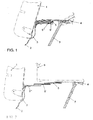
- the gap cover according to the invention is between an adjustable seat arrangement, which comprises a seat back 1 and a seat frame 2, and at least one Load compartment floor 4 is provided.
- the gap cover has at least one cover element on, which via a spring holder 3 for longitudinal displacement with the seat frame. 2 connected is.
- the spring holder 3 is preferably designed as a leaf spring element and made of spring steel, wherein the spring holder is biased such that on the Covering a spring force, in particular on the seat back 1, acts, so regardless of the position of the seat assembly and also the inclination of the seat back. 1 at any time provided between the seat assembly and the load compartment floor 4 gap is covered by the gap cover according to the invention.
- the load compartment floor 4 can, as indicated in Figure 1, both be folded up, as well as taken be moved and in a lower position, thus increasing the loading volume enlarge.
- FIG. 1 a normal sitting position is shown, wherein as a covering z.
- FIG. 2 a cargo position is shown, in which a partially illustrated load 6 is shown the load compartment floor and the gap cover according to the invention is stored.
- a partially illustrated load 6 is shown the load compartment floor and the gap cover according to the invention is stored.
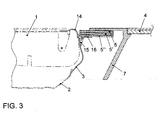
- all plates 5, 5 ', 5 "telescoped to each other arranged to the relatively large gap between the seat back 1 and the Cover load compartment floor 4 completely.
- FIG. 4 schematically shows the removal of the plates provided as cover element 5, 5 ', 5 ".
- the plates 5, 5', 5" are at least partially formed by a housing 7, which is releasably attached to a cargo space cover.
- a Detailed illustration is shown in Figure 11, in which a guide profile 8 at the Laderaumveritate 11 is provided, wherein the housing 7 slidably in the Guide profile 8 is added, so that the housing 7 with the plates 5, 5 ', 5 ", as in Figure 4 indicated by the dashed line, can be removed.
- This can be a Recessed recess 9 may be provided, in which an actuating element 10 for a spring-loaded crash lock is located.
- the Spring holder 3 on the seat frame 2 by means of at least one fastening screw 20th screwed on.
- Figure 5 is a section of the cut telescopic guide between the individual Plates 5, 5 ', 5 “shown .
- the telescopic guide of the individual plates 5, 5', 5" is thereby realized via ball spring elements 18 and guide pins or limiting pins 19.
- By the guide pins or limiting pins 19 it is possible that always the maximum possible number of plates 5, 5 ', 5 “are telescoped together In addition, a disintegration of the plates after removal from the loading space prevented.
- the spring-loaded crash lock is shown in detail. It is again the recessed grip 9 shown in which engages one end of the actuating element 10. The other end of the actuating element 10 is in a recess of the Cargo space trim 11 engaged or trapped.
- the actuating element 10 of Crash lock is coupled with a leg spring 12 for spring loading. To the Actuation of the crash lock, the actuator 10 about an axis thirteenth be rotated against the spring force of the leg spring 12, so to remove the housing 7, the entanglement or locking between the actuator 10th and the luggage compartment cover 11 is released.
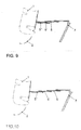
- FIGS. 7 to 10 the extraction process of the gap cover according to the invention is shown schematically in four different positions.
- the plates 5, 5', 5" arranged parallel to each other and pulled something out.
- the Plate 5 completely pulled out, while the plates 5 'and 5 "parallel to each other are arranged.
- the fully extended state of Plates 5, 5 ', 5 "are shown in Figures 7 to 10 is the pen of the invention 3, as is known from Figures 1 to 3, not shown.
- FIG 12 is a possible embodiment of the spring holder 3 as a leaf spring element shown.
- the leaf spring element is made of spring steel, z. As CK70 or the like.
- On the spring holder 3 are sliding plates 14, 14 ', which are also made of steel are.
- the sliding plates 14, 14 ' are on the seat back 1, as shown in Figures 1 to 3, attached to the spring holder 3 facing portion of the seat back 1.
- the Sliding plates 14, 14 ' have the task, in particular the seat back from damage, z. B. by the pen 3 to protect.
- the spring holder 3 has eyes 15, 15 'in which corresponding hooks 16, 16 'can be inserted.
- FIG. 13 is a three-dimensional representation of the gap cover according to the invention shown using a split seat assembly.
- the gap cover invention divided into two systems quasi. In this way can also at different positions of the split seat assembly of each arising gap can be safely covered. This is apparent from Figure 13, since different extension positions of the two systems of the invention Gap cover are shown.
- FIGS. 14 to 16 a second possible embodiment is shown in each case.
- the two embodiments also common elements, such. B. in particular the pen holder 3, use. Further is It is conceivable that the two embodiments also suitably combined can be.
- the second embodiment differs essentially from the first embodiment Embodiment in that in the inventive gap cover only a plate member 5 is provided as a cover member.
- the plate element 5 is at This embodiment can be inserted into a receptacle 17 and the gap cover also pulled out again, so that in a longitudinal adjustment of the seating arrangement of resulting gap between the seat back 1 and the load compartment floor 4 is covered.
- a kind of closed thrust is used as a guide. It
- other versions such. As a blind cover or vertical Gears conceivable.
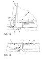
- FIG. 14 shows a normal seating position of the seat arrangement, in which the plate 5 only a little pulled out by the pen holder 3.
- FIG. 15 shows a cargo position in which the load 6 is in the cargo hold located. In this position, the plate 5 is completely out of the receptacle 17th pulled out.
- the spring holder 3 ' comprises a holder 3b, on which a rocker 3a by means of an axis 21 is articulated. By the two springs 23, 23 ', the rocker 3a is spring-loaded the holder 3b arranged. Further, two sliding plates 14 "on the seat back 1 of Seat arrangement attached, wherein in Figure 17, only a sliding plate 14 "is shown Sliding plates 14 "correspond in each case with a contact element 22, 22 ', which is arranged in each case on the rocker 3a. To the pen holder 3 'to the plate 5 "to are eyelets 15 ", 15" 'on one of the plate 5 "facing portion of Swingarm 3a provided. The holder 3b can with not shown Fixing screws 20 are attached to the seat frame 2, wherein for corresponding openings 24 are provided on the holder 3b.
Landscapes
- Engineering & Computer Science (AREA)
- Mechanical Engineering (AREA)
- Aviation & Aerospace Engineering (AREA)
- Transportation (AREA)
- Seats For Vehicles (AREA)
- Body Structure For Vehicles (AREA)
- Automobile Manufacture Line, Endless Track Vehicle, Trailer (AREA)
Abstract
Description
- Figur 1
- eine geschnittene Ansicht eines ersten Ausführungsbeispiels einer erfindungsgemäßen Spaltabdeckung zwischen einer Sitzanordnung in einer normalen Sitzposition und einem Laderaumboden;
- Figur 2
- eine geschnittene Ansicht der erfindungsgemäßen Spaltabdeckung gemäß Figur 1 der Sitzanordnung, in der diese ihre maximale Verstellposition nach vorne einnimmt;
- Figur 3
- eine geschnittene Ansicht der erfindungsgemäßen Spaltabdeckung gemäß Figur 1 bei geklappter Sitzanordnung;
- Figur 4
- eine schematische Ansicht während einer Entnahme der als Abdeckelement vorgesehenen in einem Gehäuse gelagerten und geführten Teleskop-Platten der erfindungsgemäßen Spaltabdeckung;
- Figur 5
- eine geschnittene Teilansicht der in einem Gehäuse teleskopierbar aufgenommenen Platten der erfindungsgemäßen Spaltabdeckung;
- Figur 6
- eine geschnittene Teilansicht des mit den Platten entnehmbaren Gehäuses, welches durch eine Crashverriegelung gesichert ist;
- Figuren 7 bis 10
- schematische Ansichten eines Ausziehvorganges der erfindungsgemäßen Spaltabdeckung in verschiedenen Stellungen;
- Figur 11
- eine geschnittene Teilansicht des in einem Führungsprofil der Laderaumverkleidung verschiebbar gehaltenen Gehäuses der erfindungsgemäßen Spaltabdeckung;
- Figur 12
- eine dreidimensionale Ansicht eines Federhalters der erfindungsgemäßen Spaltabdeckung mit anliegenden Gleitblechen;
- Figur 13
- eine dreidimensionale Ansicht der erfindungsgemäßen Spaltabdeckung für eine geteilte Sitzanordnung;
- Figur 14
- eine geschnittene Ansicht eines zweiten Ausführungsbeispiels der erfindungsgemäßen Spaltabdeckung zwischen einer Sitzanordnung in einer normalen Sitzposition und einem Laderaumboden;
- Figur 15
- eine geschnittene Ansicht der erfindungsgemäßen Spaltabdeckung gemäß Figur 14 in einer Cargoposition der Sitzanordnung;
- Figur 16
- eine geschnittene Ansicht der erfindungsgemäßen Spaltabdeckung gemäß Figur 14 bei geklappter Sitzanordnung; und
- Figur 17
- eine dreidimensionale Ansicht einer alternativen Ausgestaltung des Federhalters der erfindungsgemäßen Spaltabdeckung.
- 1
- Sitzlehne
- 2
- Sitzgestell
- 3,3'
- Federhalter
- 4
- Laderaumboden
- 5,5',5"
- Platte
- 6
- Ladegut
- 7
- Gehäuse
- 8
- Führungsprofil
- 9
- Griffmulde
- 10
- Betätigungselement
- 11
- Laderaumverkleidung
- 12
- Schenkelfeder
- 13
- Achse
- 14,14',14"
- Gleitblech
- 15,15',15",15"'
- Ösen
- 16,16'
- Haken
- 17
- Aufnahme
- 18
- Kugelfederelement
- 19
- Führungs- bzw. Begrenzungsstift
- 20
- Befestigungsschraube
- 21
- Achse
- 22,22'
- Kontaktelement
- 23,23'
- Feder
- 24
- Öffnungen
Claims (16)
- Spaltabdeckung zwischen einer verstellbaren Sitzanordnung und zumindest einem Laderaumboden, mit wenigstens einem Abdeckelement, welches über ein Federelement zum Längsverschieben mit der Sitzanordnung gekoppelt ist, dadurch gekennzeichnet, dass als Federelement zumindest ein Federhalter (3, 3') vorgesehen ist, welcher derart vorgespannt ist, dass das Abdeckelement durch eine Federkraft auf die Sitzanordnung wirkt.
- Spaltabdeckung nach Anspruch 1, dadurch gekennzeichnet, dass jeder Federhalter (3, 3') an dem Sitzgestell (2) der Sitzanordnung befestigt ist.
- Spaltabdeckung nach Anspruch 1 oder 2, dadurch gekennzeichnet, dass jeder Federhalter (3, 3') mit dem Abdeckelement lösbar verbunden ist.
- Spaltabdeckung nach Anspruch 3, dadurch gekennzeichnet, dass das Abdeckelement zumindest einen Haken (16, 16') aufweist, welcher in eine entsprechende Öse (15, 15', 15") an dem Federhalter (3, 3') eingehakt ist.
- Spaltabdeckung nach einem der vorangehenden Ansprüche, dadurch gekennzeichnet, dass als Abdeckelement zumindest eine Platte (5, 5', 5") vorgesehen ist.
- Spaltabdeckung nach Anspruch 5, dadurch gekennzeichnet, dass die Platte (5) verschiebbar ausgebildet ist und in eine Aufnahme (17) etwa parallel zu dem Laderaumboden (4) einschiebbar ist.
- Spaltabdeckung nach Anspruch 5, dadurch gekennzeichnet, dass mehrere zueinander teleskopierbare Platten (5, 5', 5") vorgesehen sind.
- Spaltabdeckung nach Anspruch 7, dadurch gekennzeichnet, dass die Platten (5, 5', 5") über Kugelfederelemente (18) und entsprechende Anschlägen derart gekoppelt sind, dass die Platten (5, 5', 5") zunächst gemeinsam ausziehbar sind, bis jeweils eine Platte (5, 5', 5") vollständig herausgezogen ist.
- Spaltabdeckung nach Anspruch 8, dadurch gekennzeichnet, dass als Anschläge Führungsstifte oder Begrenzungsstifte (19) vorgesehen sind.
- Spaltabdeckung nach Anspruch 7 oder 8, dadurch gekennzeichnet, dass die Platten (5, 5', 5") zumindest teilweise von einem Gehäuse (7) aufgenommen sind.
- Spaltabdeckung nach Anspruch 10, dadurch gekennzeichnet, dass das Gehäuse (7) lösbar an der Laderaumverkleidung (11) befestigt ist.
- Spaltabdeckung nach Anspruch 10 oder 11, dadurch gekennzeichnet, dass zur Befestigung des Gehäuses (7) eine federbelastete Crashverriegelung vorgesehen ist.
- Spaltabdeckung nach einem der vorangehenden Ansprüche, dadurch gekennzeichnet, dass zumindest ein Gleitblech (14, 14', 14") an dem dem Federhalter (3, 3') zugewandten Abschnitt der Sitzlehne (1) der Sitzanordnung befestigt ist.
- Spaltabdeckung nach Anspruch 1, dadurch gekennzeichnet, dass als Federhalter (3) ein Blattfederelement vorgesehen ist.
- Spaltabdeckung nach Anspruch 13, dadurch gekennzeichnet, dass als Werkstoff für das Blattfederelement Federstahl vorgesehen ist.
- Spaltabdeckung nach einem der vorangehenden Ansprüche, dadurch gekennzeichnet, dass bei einer geteilten Sitzanordnung jeweils ein Federhalter (3, 3') für jedes Abdeckelement vorgesehen ist, wobei die beiden benachbarten Abdeckelemente in einem Gehäuse (7) oder einer Aufnahme (17) aufgenommen sind.
Applications Claiming Priority (2)
| Application Number | Priority Date | Filing Date | Title |
|---|---|---|---|
| DE10332375 | 2003-07-17 | ||
| DE10332375A DE10332375A1 (de) | 2003-07-17 | 2003-07-17 | Spaltabdeckung zwischen einem Laderaumboden und einer Sitzanordnung eines Fahrzeuges |
Publications (3)
| Publication Number | Publication Date |
|---|---|
| EP1498304A2 true EP1498304A2 (de) | 2005-01-19 |
| EP1498304A3 EP1498304A3 (de) | 2005-06-29 |
| EP1498304B1 EP1498304B1 (de) | 2010-01-20 |
Family
ID=33461960
Family Applications (1)
| Application Number | Title | Priority Date | Filing Date |
|---|---|---|---|
| EP03025931A Expired - Lifetime EP1498304B1 (de) | 2003-07-17 | 2003-11-13 | Spaltabdeckung zwischen einem Laderaumboden und einer Sitzanordnung eines Fahrzeuges |
Country Status (3)
| Country | Link |
|---|---|
| EP (1) | EP1498304B1 (de) |
| AT (1) | ATE455673T1 (de) |
| DE (2) | DE10332375A1 (de) |
Cited By (4)
| Publication number | Priority date | Publication date | Assignee | Title |
|---|---|---|---|---|
| FR3026071A1 (fr) * | 2014-09-24 | 2016-03-25 | Renault Sas | Agencement d'un plancher a l'interieur d'un coffre de vehicule automobile comportant des sieges escamotables |
| CN106585501A (zh) * | 2015-10-15 | 2017-04-26 | 福特全球技术公司 | 一种滑动的货物后箱盖 |
| US11358503B1 (en) | 2021-03-22 | 2022-06-14 | Honda Motor Co., Ltd. | Seal for a trim member of a vehicle seat back |
| US20240181943A1 (en) * | 2022-12-05 | 2024-06-06 | Hyundai Motor Company | Luggage Gap Cover Device for Vehicle Rear Seat |
Families Citing this family (6)
| Publication number | Priority date | Publication date | Assignee | Title |
|---|---|---|---|---|
| DE102008025333B4 (de) * | 2008-05-27 | 2020-01-16 | Bayerische Motoren Werke Aktiengesellschaft | Spaltabdeckung für ein Kraftfahrzeug |
| DE102009060162A1 (de) * | 2009-12-23 | 2011-06-30 | Volkswagen AG, 38440 | Laderaumabdeckung für einen Laderaum eines Fahrzeugs |
| DE102010052455A1 (de) * | 2010-11-24 | 2012-05-24 | GM Global Technology Operations LLC | Kraftfahrzeug mit hinterer Sitzanordnung und Ladeboden |
| DE102015208107B4 (de) | 2014-05-16 | 2026-04-30 | Ford Global Technologies, Llc | Laderaumabdeckung |
| JP6871046B2 (ja) * | 2017-04-03 | 2021-05-12 | トヨタ紡織株式会社 | 乗物用ラゲッジフロアの隙隠し構造 |
| DE102021118526A1 (de) | 2021-07-19 | 2023-01-19 | Audi Aktiengesellschaft | Verkleidungsanordnung für eine Rückseite einer zwischen einem eingefahrenen und einem ausgefahrenen Zustand verfahrbaren flexiblen Anzeigeeinheit sowie Anzeigevorrichtung mit der Anzeigeeinheit und der Verkleidungsanordnung sowie Kraftfahrzeug |
Family Cites Families (11)
| Publication number | Priority date | Publication date | Assignee | Title |
|---|---|---|---|---|
| GB1249787A (en) * | 1970-03-20 | 1971-10-13 | Ford Motor Co | Estate car rear seat |
| DE2752431C3 (de) * | 1977-11-24 | 1981-10-29 | Adam Opel AG, 6090 Rüsselsheim | Fahrzeugsitz mit umklappbarer Rückenlehne |
| JP2977472B2 (ja) * | 1995-10-06 | 1999-11-15 | 本田技研工業株式会社 | 車両用シートのヘッドレスト収納機構 |
| US5658046A (en) * | 1996-01-16 | 1997-08-19 | Lear Corporation | Vehicle seat trim cover attachment strip |
| DE19838734B4 (de) * | 1998-08-26 | 2010-09-02 | Adam Opel Ag | Hintersitzanordnung für ein Kraftfahrzeug |
| DE10012590B4 (de) * | 2000-03-15 | 2011-06-01 | GM Global Technology Operations LLC, ( n. d. Ges. d. Staates Delaware ), Detroit | Vor einem Laderaum eines Kraftfahrzeuges angeordnete Sitzanordnung |
| DE20009327U1 (de) * | 2000-05-24 | 2001-09-27 | Johnson Controls GmbH, 51399 Burscheid | Flexible Spaltabdeckung |
| JP2002067808A (ja) * | 2000-08-31 | 2002-03-08 | Nissan Motor Co Ltd | 車両用荷室構造 |
| JP2002067762A (ja) * | 2000-09-04 | 2002-03-08 | Tachi S Co Ltd | 前後調整可能な折りたたみリア・シート |
| DE10109651B4 (de) * | 2001-02-28 | 2014-03-13 | Volkswagen Ag | Abdeckung für einen Spalt hinter einer Rücksitzlehne in einem Fahrzeug |
| JP2003026050A (ja) * | 2001-07-11 | 2003-01-29 | Fuji Heavy Ind Ltd | 自動車のボデー構造 |
-
2003
- 2003-07-17 DE DE10332375A patent/DE10332375A1/de not_active Withdrawn
- 2003-11-13 DE DE50312359T patent/DE50312359D1/de not_active Expired - Lifetime
- 2003-11-13 EP EP03025931A patent/EP1498304B1/de not_active Expired - Lifetime
- 2003-11-13 AT AT03025931T patent/ATE455673T1/de not_active IP Right Cessation
Cited By (7)
| Publication number | Priority date | Publication date | Assignee | Title |
|---|---|---|---|---|
| FR3026071A1 (fr) * | 2014-09-24 | 2016-03-25 | Renault Sas | Agencement d'un plancher a l'interieur d'un coffre de vehicule automobile comportant des sieges escamotables |
| WO2016046473A1 (fr) * | 2014-09-24 | 2016-03-31 | Renault S.A.S. | Agencement d'un plancher a l'interieur d'un coffre de vehicule automobile comportant des sieges escamotables |
| CN106585501A (zh) * | 2015-10-15 | 2017-04-26 | 福特全球技术公司 | 一种滑动的货物后箱盖 |
| CN106585501B (zh) * | 2015-10-15 | 2022-04-29 | 福特全球技术公司 | 一种滑动的货物后箱盖 |
| US11358503B1 (en) | 2021-03-22 | 2022-06-14 | Honda Motor Co., Ltd. | Seal for a trim member of a vehicle seat back |
| US20240181943A1 (en) * | 2022-12-05 | 2024-06-06 | Hyundai Motor Company | Luggage Gap Cover Device for Vehicle Rear Seat |
| US12365273B2 (en) * | 2022-12-05 | 2025-07-22 | Hyundai Motor Company | Luggage gap cover device for vehicle rear seat |
Also Published As
| Publication number | Publication date |
|---|---|
| DE10332375A1 (de) | 2005-02-03 |
| ATE455673T1 (de) | 2010-02-15 |
| EP1498304A3 (de) | 2005-06-29 |
| EP1498304B1 (de) | 2010-01-20 |
| DE50312359D1 (de) | 2010-03-11 |
Similar Documents
| Publication | Publication Date | Title |
|---|---|---|
| DE102004044970B4 (de) | Kopfstützenanordnung mit Nockenantrieb in vier Richtungen | |
| DE69736064T2 (de) | Fahrzeugsitzaufhängung mit niedriger profilkonstruktion und kombiniertem längenverstellmechanismus | |
| DE3726711C2 (de) | ||
| DE69604373T2 (de) | Sitz mit veränderlicher Anordnung für Kraftfahrzeuge | |
| DE10154659C5 (de) | Zusammenschiebbare Lenksäulenanordnung für ein Fahrzeug | |
| DE20314237U1 (de) | Memory-Einrichtung für eine Schienenlängsführung eines Kraftfahrzeuges | |
| EP0754594B1 (de) | Abdeckeinrichtung mit hoher Crashsicherheit | |
| DE19647448C2 (de) | Längsverstellvorrichtung für Sitze, insbesondere Kraftfahrzeugsitze | |
| DE60308147T2 (de) | Fahrzeugsitz mit kopfstütze welche unabhängig von der rückenlehne ist | |
| EP1854657B1 (de) | Überbrückungseinrichtung für eine Vertiefung zwischen einem Fahrzeugsitz und einem Laderaumboden | |
| EP1498304B1 (de) | Spaltabdeckung zwischen einem Laderaumboden und einer Sitzanordnung eines Fahrzeuges | |
| DE10359226A1 (de) | Rollstuhl-Halterungssystem | |
| EP0928717B1 (de) | Verstelleinrichtung für eine Fahrzeugsitz-Rückenlehne | |
| EP2139716A1 (de) | Fahrzeugsitz | |
| DE102019111393B4 (de) | Sicherheitsgurtschloss-befestigungssystem für ein fahrzeug | |
| DE10057572C2 (de) | Laderaum-Abdeck- und/oder Laderaum-Trennvorrichtung für den Lade-oder Gepäckraum eines Fahrzeugs | |
| DE102020111898A1 (de) | Beinstützensystem für sitzbaugruppe | |
| DE102005031252B4 (de) | Rückenlehneneinheit eines Kraftfahrzeugsitzes | |
| EP2226219A1 (de) | System eines herausnehmbaren Ladebodens | |
| DE102014226133B4 (de) | Einstellvorrichtung für eine Rücksitzlehne | |
| DE202015105429U1 (de) | Rollstuhlhalterung für Fahrzeuge | |
| EP4676773A1 (de) | Notentriegelung für ein sitzsystem in einem fahrzeug | |
| DE102020115966B4 (de) | Kopfstütze für einen fahrzeugsitz sowie fahrzeugsitz | |
| DE69818616T2 (de) | Anordnung für einen ausnehmbaren und in Längsrichtung verstellbaren Sitz im Innenraum eines Kraftfahrzeuges | |
| DE102023000714B4 (de) | Aus einem Trittbrett eines Fahrzeugs ausfahrbarer Außensitz sowie ein mit demselben ausgestattetes Fahrzeug |
Legal Events
| Date | Code | Title | Description |
|---|---|---|---|
| PUAI | Public reference made under article 153(3) epc to a published international application that has entered the european phase |
Free format text: ORIGINAL CODE: 0009012 |
|
| AK | Designated contracting states |
Kind code of ref document: A2 Designated state(s): AT BE BG CH CY CZ DE DK EE ES FI FR GB GR HU IE IT LI LU MC NL PT RO SE SI SK TR |
|
| AX | Request for extension of the european patent |
Extension state: AL LT LV MK |
|
| PUAL | Search report despatched |
Free format text: ORIGINAL CODE: 0009013 |
|
| AK | Designated contracting states |
Kind code of ref document: A3 Designated state(s): AT BE BG CH CY CZ DE DK EE ES FI FR GB GR HU IE IT LI LU MC NL PT RO SE SI SK TR |
|
| AX | Request for extension of the european patent |
Extension state: AL LT LV MK |
|
| RIC1 | Information provided on ipc code assigned before grant |
Ipc: 7B 60N 2/36 A Ipc: 7B 60N 2/30 B Ipc: 7B 60N 2/06 B Ipc: 7B 60R 13/01 B |
|
| 17P | Request for examination filed |
Effective date: 20051229 |
|
| AKX | Designation fees paid |
Designated state(s): AT BE BG CH CY CZ DE DK EE ES FI FR GB GR HU IE IT LI LU MC NL PT RO SE SI SK TR |
|
| GRAP | Despatch of communication of intention to grant a patent |
Free format text: ORIGINAL CODE: EPIDOSNIGR1 |
|
| GRAS | Grant fee paid |
Free format text: ORIGINAL CODE: EPIDOSNIGR3 |
|
| GRAA | (expected) grant |
Free format text: ORIGINAL CODE: 0009210 |
|
| AK | Designated contracting states |
Kind code of ref document: B1 Designated state(s): AT BE BG CH CY CZ DE DK EE ES FI FR GB GR HU IE IT LI LU MC NL PT RO SE SI SK TR |
|
| REG | Reference to a national code |
Ref country code: GB Ref legal event code: FG4D Free format text: NOT ENGLISH |
|
| REG | Reference to a national code |
Ref country code: CH Ref legal event code: EP |
|
| REG | Reference to a national code |
Ref country code: IE Ref legal event code: FG4D |
|
| REF | Corresponds to: |
Ref document number: 50312359 Country of ref document: DE Date of ref document: 20100311 Kind code of ref document: P |
|
| REG | Reference to a national code |
Ref country code: NL Ref legal event code: VDEP Effective date: 20100120 |
|
| PG25 | Lapsed in a contracting state [announced via postgrant information from national office to epo] |
Ref country code: ES Free format text: LAPSE BECAUSE OF FAILURE TO SUBMIT A TRANSLATION OF THE DESCRIPTION OR TO PAY THE FEE WITHIN THE PRESCRIBED TIME-LIMIT Effective date: 20100501 Ref country code: NL Free format text: LAPSE BECAUSE OF FAILURE TO SUBMIT A TRANSLATION OF THE DESCRIPTION OR TO PAY THE FEE WITHIN THE PRESCRIBED TIME-LIMIT Effective date: 20100120 Ref country code: PT Free format text: LAPSE BECAUSE OF FAILURE TO SUBMIT A TRANSLATION OF THE DESCRIPTION OR TO PAY THE FEE WITHIN THE PRESCRIBED TIME-LIMIT Effective date: 20100520 |
|
| REG | Reference to a national code |
Ref country code: IE Ref legal event code: FD4D |
|
| PG25 | Lapsed in a contracting state [announced via postgrant information from national office to epo] |
Ref country code: SI Free format text: LAPSE BECAUSE OF FAILURE TO SUBMIT A TRANSLATION OF THE DESCRIPTION OR TO PAY THE FEE WITHIN THE PRESCRIBED TIME-LIMIT Effective date: 20100120 Ref country code: FI Free format text: LAPSE BECAUSE OF FAILURE TO SUBMIT A TRANSLATION OF THE DESCRIPTION OR TO PAY THE FEE WITHIN THE PRESCRIBED TIME-LIMIT Effective date: 20100120 |
|
| PG25 | Lapsed in a contracting state [announced via postgrant information from national office to epo] |
Ref country code: SE Free format text: LAPSE BECAUSE OF FAILURE TO SUBMIT A TRANSLATION OF THE DESCRIPTION OR TO PAY THE FEE WITHIN THE PRESCRIBED TIME-LIMIT Effective date: 20100120 Ref country code: IE Free format text: LAPSE BECAUSE OF FAILURE TO SUBMIT A TRANSLATION OF THE DESCRIPTION OR TO PAY THE FEE WITHIN THE PRESCRIBED TIME-LIMIT Effective date: 20100120 Ref country code: GR Free format text: LAPSE BECAUSE OF FAILURE TO SUBMIT A TRANSLATION OF THE DESCRIPTION OR TO PAY THE FEE WITHIN THE PRESCRIBED TIME-LIMIT Effective date: 20100421 Ref country code: EE Free format text: LAPSE BECAUSE OF FAILURE TO SUBMIT A TRANSLATION OF THE DESCRIPTION OR TO PAY THE FEE WITHIN THE PRESCRIBED TIME-LIMIT Effective date: 20100120 Ref country code: CY Free format text: LAPSE BECAUSE OF FAILURE TO SUBMIT A TRANSLATION OF THE DESCRIPTION OR TO PAY THE FEE WITHIN THE PRESCRIBED TIME-LIMIT Effective date: 20100120 Ref country code: RO Free format text: LAPSE BECAUSE OF FAILURE TO SUBMIT A TRANSLATION OF THE DESCRIPTION OR TO PAY THE FEE WITHIN THE PRESCRIBED TIME-LIMIT Effective date: 20100120 |
|
| PLBE | No opposition filed within time limit |
Free format text: ORIGINAL CODE: 0009261 |
|
| STAA | Information on the status of an ep patent application or granted ep patent |
Free format text: STATUS: NO OPPOSITION FILED WITHIN TIME LIMIT |
|
| PG25 | Lapsed in a contracting state [announced via postgrant information from national office to epo] |
Ref country code: CZ Free format text: LAPSE BECAUSE OF FAILURE TO SUBMIT A TRANSLATION OF THE DESCRIPTION OR TO PAY THE FEE WITHIN THE PRESCRIBED TIME-LIMIT Effective date: 20100120 Ref country code: BG Free format text: LAPSE BECAUSE OF FAILURE TO SUBMIT A TRANSLATION OF THE DESCRIPTION OR TO PAY THE FEE WITHIN THE PRESCRIBED TIME-LIMIT Effective date: 20100420 Ref country code: SK Free format text: LAPSE BECAUSE OF FAILURE TO SUBMIT A TRANSLATION OF THE DESCRIPTION OR TO PAY THE FEE WITHIN THE PRESCRIBED TIME-LIMIT Effective date: 20100120 |
|
| 26N | No opposition filed |
Effective date: 20101021 |
|
| PG25 | Lapsed in a contracting state [announced via postgrant information from national office to epo] |
Ref country code: DK Free format text: LAPSE BECAUSE OF FAILURE TO SUBMIT A TRANSLATION OF THE DESCRIPTION OR TO PAY THE FEE WITHIN THE PRESCRIBED TIME-LIMIT Effective date: 20100120 |
|
| PG25 | Lapsed in a contracting state [announced via postgrant information from national office to epo] |
Ref country code: IT Free format text: LAPSE BECAUSE OF FAILURE TO SUBMIT A TRANSLATION OF THE DESCRIPTION OR TO PAY THE FEE WITHIN THE PRESCRIBED TIME-LIMIT Effective date: 20100120 |
|
| BERE | Be: lapsed |
Owner name: VOLKSWAGEN A.G. Effective date: 20101130 |
|
| PG25 | Lapsed in a contracting state [announced via postgrant information from national office to epo] |
Ref country code: MC Free format text: LAPSE BECAUSE OF NON-PAYMENT OF DUE FEES Effective date: 20101130 |
|
| REG | Reference to a national code |
Ref country code: CH Ref legal event code: PL |
|
| PG25 | Lapsed in a contracting state [announced via postgrant information from national office to epo] |
Ref country code: CH Free format text: LAPSE BECAUSE OF NON-PAYMENT OF DUE FEES Effective date: 20101130 Ref country code: LI Free format text: LAPSE BECAUSE OF NON-PAYMENT OF DUE FEES Effective date: 20101130 |
|
| PG25 | Lapsed in a contracting state [announced via postgrant information from national office to epo] |
Ref country code: BE Free format text: LAPSE BECAUSE OF NON-PAYMENT OF DUE FEES Effective date: 20101130 |
|
| REG | Reference to a national code |
Ref country code: AT Ref legal event code: MM01 Ref document number: 455673 Country of ref document: AT Kind code of ref document: T Effective date: 20101113 |
|
| PG25 | Lapsed in a contracting state [announced via postgrant information from national office to epo] |
Ref country code: AT Free format text: LAPSE BECAUSE OF NON-PAYMENT OF DUE FEES Effective date: 20101113 |
|
| PG25 | Lapsed in a contracting state [announced via postgrant information from national office to epo] |
Ref country code: HU Free format text: LAPSE BECAUSE OF FAILURE TO SUBMIT A TRANSLATION OF THE DESCRIPTION OR TO PAY THE FEE WITHIN THE PRESCRIBED TIME-LIMIT Effective date: 20100721 Ref country code: LU Free format text: LAPSE BECAUSE OF NON-PAYMENT OF DUE FEES Effective date: 20101113 |
|
| PG25 | Lapsed in a contracting state [announced via postgrant information from national office to epo] |
Ref country code: TR Free format text: LAPSE BECAUSE OF FAILURE TO SUBMIT A TRANSLATION OF THE DESCRIPTION OR TO PAY THE FEE WITHIN THE PRESCRIBED TIME-LIMIT Effective date: 20100120 |
|
| REG | Reference to a national code |
Ref country code: FR Ref legal event code: PLFP Year of fee payment: 13 |
|
| PGFP | Annual fee paid to national office [announced via postgrant information from national office to epo] |
Ref country code: GB Payment date: 20151130 Year of fee payment: 13 |
|
| PGFP | Annual fee paid to national office [announced via postgrant information from national office to epo] |
Ref country code: FR Payment date: 20151130 Year of fee payment: 13 |
|
| GBPC | Gb: european patent ceased through non-payment of renewal fee |
Effective date: 20161113 |
|
| REG | Reference to a national code |
Ref country code: FR Ref legal event code: ST Effective date: 20170731 |
|
| PG25 | Lapsed in a contracting state [announced via postgrant information from national office to epo] |
Ref country code: FR Free format text: LAPSE BECAUSE OF NON-PAYMENT OF DUE FEES Effective date: 20161130 |
|
| PG25 | Lapsed in a contracting state [announced via postgrant information from national office to epo] |
Ref country code: GB Free format text: LAPSE BECAUSE OF NON-PAYMENT OF DUE FEES Effective date: 20161113 |
|
| PGFP | Annual fee paid to national office [announced via postgrant information from national office to epo] |
Ref country code: DE Payment date: 20201130 Year of fee payment: 18 |
|
| REG | Reference to a national code |
Ref country code: DE Ref legal event code: R119 Ref document number: 50312359 Country of ref document: DE |
|
| PG25 | Lapsed in a contracting state [announced via postgrant information from national office to epo] |
Ref country code: DE Free format text: LAPSE BECAUSE OF NON-PAYMENT OF DUE FEES Effective date: 20220601 |