EP1498203B2 - Stirnfräser - Google Patents
Stirnfräser Download PDFInfo
- Publication number
- EP1498203B2 EP1498203B2 EP04015346.2A EP04015346A EP1498203B2 EP 1498203 B2 EP1498203 B2 EP 1498203B2 EP 04015346 A EP04015346 A EP 04015346A EP 1498203 B2 EP1498203 B2 EP 1498203B2
- Authority
- EP
- European Patent Office
- Prior art keywords
- cutting edge
- milling cutter
- face milling
- cutter according
- lower cutting
- Prior art date
- Legal status (The legal status is an assumption and is not a legal conclusion. Google has not performed a legal analysis and makes no representation as to the accuracy of the status listed.)
- Expired - Lifetime
Links
- 230000002093 peripheral effect Effects 0.000 claims abstract description 7
- 238000003801 milling Methods 0.000 claims description 19
- 239000000463 material Substances 0.000 claims description 5
- 238000000926 separation method Methods 0.000 claims 1
- 238000005476 soldering Methods 0.000 claims 1
- 238000003754 machining Methods 0.000 description 2
- 239000002184 metal Substances 0.000 description 2
- 230000015572 biosynthetic process Effects 0.000 description 1
- 238000005219 brazing Methods 0.000 description 1
- 230000001681 protective effect Effects 0.000 description 1
- 230000007704 transition Effects 0.000 description 1
Images

Classifications
-
- B—PERFORMING OPERATIONS; TRANSPORTING
- B23—MACHINE TOOLS; METAL-WORKING NOT OTHERWISE PROVIDED FOR
- B23C—MILLING
- B23C5/00—Milling-cutters
- B23C5/02—Milling-cutters characterised by the shape of the cutter
- B23C5/10—Shank-type cutters, i.e. with an integral shaft
-
- B—PERFORMING OPERATIONS; TRANSPORTING
- B23—MACHINE TOOLS; METAL-WORKING NOT OTHERWISE PROVIDED FOR
- B23C—MILLING
- B23C5/00—Milling-cutters
- B23C5/02—Milling-cutters characterised by the shape of the cutter
- B23C5/10—Shank-type cutters, i.e. with an integral shaft
- B23C5/109—Shank-type cutters, i.e. with an integral shaft with removable cutting inserts
-
- B—PERFORMING OPERATIONS; TRANSPORTING
- B23—MACHINE TOOLS; METAL-WORKING NOT OTHERWISE PROVIDED FOR
- B23C—MILLING
- B23C2210/00—Details of milling cutters
- B23C2210/08—Side or top views of the cutting edge
- B23C2210/084—Curved cutting edges
-
- Y—GENERAL TAGGING OF NEW TECHNOLOGICAL DEVELOPMENTS; GENERAL TAGGING OF CROSS-SECTIONAL TECHNOLOGIES SPANNING OVER SEVERAL SECTIONS OF THE IPC; TECHNICAL SUBJECTS COVERED BY FORMER USPC CROSS-REFERENCE ART COLLECTIONS [XRACs] AND DIGESTS
- Y10—TECHNICAL SUBJECTS COVERED BY FORMER USPC
- Y10T—TECHNICAL SUBJECTS COVERED BY FORMER US CLASSIFICATION
- Y10T407/00—Cutters, for shaping
- Y10T407/19—Rotary cutting tool
- Y10T407/1906—Rotary cutting tool including holder [i.e., head] having seat for inserted tool
- Y10T407/1908—Face or end mill
-
- Y—GENERAL TAGGING OF NEW TECHNOLOGICAL DEVELOPMENTS; GENERAL TAGGING OF CROSS-SECTIONAL TECHNOLOGIES SPANNING OVER SEVERAL SECTIONS OF THE IPC; TECHNICAL SUBJECTS COVERED BY FORMER USPC CROSS-REFERENCE ART COLLECTIONS [XRACs] AND DIGESTS
- Y10—TECHNICAL SUBJECTS COVERED BY FORMER USPC
- Y10T—TECHNICAL SUBJECTS COVERED BY FORMER US CLASSIFICATION
- Y10T407/00—Cutters, for shaping
- Y10T407/19—Rotary cutting tool
- Y10T407/1946—Face or end mill
- Y10T407/1948—Face or end mill with cutting edge entirely across end of tool [e.g., router bit, end mill, etc.]
-
- Y—GENERAL TAGGING OF NEW TECHNOLOGICAL DEVELOPMENTS; GENERAL TAGGING OF CROSS-SECTIONAL TECHNOLOGIES SPANNING OVER SEVERAL SECTIONS OF THE IPC; TECHNICAL SUBJECTS COVERED BY FORMER USPC CROSS-REFERENCE ART COLLECTIONS [XRACs] AND DIGESTS
- Y10—TECHNICAL SUBJECTS COVERED BY FORMER USPC
- Y10T—TECHNICAL SUBJECTS COVERED BY FORMER US CLASSIFICATION
- Y10T408/00—Cutting by use of rotating axially moving tool
- Y10T408/89—Tool or Tool with support
- Y10T408/909—Having peripherally spaced cutting edges
-
- Y—GENERAL TAGGING OF NEW TECHNOLOGICAL DEVELOPMENTS; GENERAL TAGGING OF CROSS-SECTIONAL TECHNOLOGIES SPANNING OVER SEVERAL SECTIONS OF THE IPC; TECHNICAL SUBJECTS COVERED BY FORMER USPC CROSS-REFERENCE ART COLLECTIONS [XRACs] AND DIGESTS
- Y10—TECHNICAL SUBJECTS COVERED BY FORMER USPC
- Y10T—TECHNICAL SUBJECTS COVERED BY FORMER US CLASSIFICATION
- Y10T409/00—Gear cutting, milling, or planing
- Y10T409/30—Milling
- Y10T409/30952—Milling with cutter holder
Definitions
- the invention relates to a face milling cutter according to the preamble of claim 1.
- the invention relates in particular to a face milling cutter for roughing, e.g. in die and mold making.
- An end mill of the type mentioned is out DE 100 52 963 A1 known. It has a shank receiving circumferentially spaced pockets in the face area cutting inserts. Each insert has three cutting edge portions which engage the workpiece. At the front end of an arcuate lower cutting edge is provided, which merges towards the periphery in a Eckschneidkante. This goes in turn into a peripheral cutting edge, which is at an angle to create an open space. With the face milling cutter, a high feed rate should be achieved with as smooth as possible tool surfaces.
- the invention has for its object to provide a face milling cutter, which allows a high feed rate with high removal rate at low load on the individual cutting edges.
- the end mill according to the invention is particularly suitable for roughing in die and mold making.
- Shank portion and tool portion are integrally molded of hard metal.
- the tool section has at least one lower cutting edge, a corner cutting edge adjoining thereto and a peripheral cutting edge.
- corresponding cutting edges are provided diametrically opposite one another.
- the lower cutting edge has a radius of 1 to 2 times a diameter d1
- the distance of the lower cutting edge from the axis of the Shank is about 0.1 to 0.2 times the diameter d1, wherein the diameter d1 is the diameter of the circle, which describes a tangent axis parallel to the rounded Eckschneidkante.
- the maximum delivery depth ap is preferably 0.05 d1, i. of the already mentioned diameter.
- the radius of the corner cutting edge is preferably 0.05 to 0.07 d1.
- the peripheral cutting edge is preferably a straight line in the section, which jumps back by a predetermined clearance angle. Thus, it does not cut along when adjusting over the infeed depth.
- the center of the circular arc for the front cutting edge has a lateral distance from the shaft axis of about 0.1 to 0.2 d1, then in the middle of the front side of the milling cutter, a region which does not occur during machining participates.
- the lower or trim edges are arcuately curved, as seen in the direction of rotation to the rear.
- the resulting opening angle of the cutting edges is preferably 15 °.
- the shank portion has a predetermined breaking point which tapers in diameter.
- lower cutting edge and Eckschneidkante are formed on a cutting element of super hard cutting material, which is attached to the tool shank by brazing.
- a super hard cutting material is eg CBN or PKD.
- the tool according to the invention enables high tooth feeds due to small feed depths.
- the cutting force is reduced and thus also the load of the individual cutting edge sections.
- a high feed rate is achieved with high removal rates.
- the end mill is generally designated 10. It is integrally formed from hard metal and has a workpiece portion 12 and a shaft portion 14 which is only partially shown.
- the shank portion is designed for clamping in the chuck of a machine tool.
- a reduced diameter transition 16 is formed between the tool portion 12 and the shaft portion 14.
- a predetermined breaking point 17 is provided, which is effective when a certain load is exceeded.
- Fig. 3 shows, diametrically opposite cutting edges 18, 20 are formed, which are bent backwards relative to the direction indicated at 22 in the direction of rotation with an opening angle B of about 15 °.
- the formation of the cutting geometry will be described below with reference to Fig. 4 first be explained further. In this case, only reference is made to the cutting edge 18.
- the cutting edge 20 is formed identically.
- the cutting edge 18 consists of a lower cutting edge or end cutting edge 24, a Eckschneidkante 26 and a peripheral cutting edge 28.
- the latter is straight in section and deviates from a tangent 30 at the circular corner cutting edge 26 by a clearance angle a back.
- the tangent 30 describes a circle of revolution with a diameter d1 to which all further dimensions given below refer.
- the center of the circular arc is offset relative to the tool axis 28 by an amount of 0.2 to 0.4 times d1. This distance a1 in the specific case is 0.125 times d1.
- the distance of the tangent point 34 at the Eckschneidkante 26 to the tangent 36 to the end cutting edge 18 perpendicular to the shaft axis 28 is 0.08 to 0.12 d1, in the specific case 0.1 times d1.
- the effective end cutting edge 24 begins at a distance a1 at the point 38.
- the shaft 24 extends inwardly towards the shaft axis 28 and thus no longer contributes to chip removal. In the middle, even a slight depression 40 can be seen.
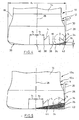
- Fig. 4 the engagement is shown with a hatched drawn workpiece section, as seen at 42. It can be seen that the infeed depth ap is relatively small, in the specific case 0.05 times d1. Only a small part of the corner cutting edge 26 therefore contributes to the removal. The end cutting edge 24 is very flat, so that very small kappa (setting angle) is obtained with a correspondingly low load on the cutting edge.
- Fig. 5 is the end mill 10a provided with approximately the same geometric properties as that of the FIGS. 1 to 4 , Identical parts are therefore provided with the same reference numerals.
- the difference to Fig. 4 is that in pockets for forming the cutting edges 18, 20 cutting elements 44 are soldered (In Fig. 5 only one element 44 is drawn.). It consists of a superhard material, such as CBN or PCD. However, nothing changes in the geometry of the cutting edge.
- the cutting edges 18, 20 in the region of the end cutting edge 24 have a Stirnfase 46, for example, with a width of 0.8 mm.
- the front clamping angle; denoted C for example, is 6 °.
- a first end free angle D is eg 8 ° and a second end free angle E is eg 16 °.
- the width of the chamfer is indicated at F.
- the cutting edge 24 has a protective chamfer 48 (edge breakage).
- the resulting chamfer angle H is 10 ° to 18 °, preferably 14 °.
- the chamfer width G is 0.06 to 0.12 mm, preferably 0.08 mm. While the rake angle C is positive, the edge break results in a negative one Rake angle in the lower area of the main cutting edge.
- Chamfer angle and width can be freely selected for different applications (materials).
Landscapes
- Engineering & Computer Science (AREA)
- Mechanical Engineering (AREA)
- Milling Processes (AREA)
- Disintegrating Or Milling (AREA)
- Diaphragms For Electromechanical Transducers (AREA)
- Processing Of Terminals (AREA)
- Nonmetal Cutting Devices (AREA)
Description
- Die Erfindung bezieht sich auf einen Stirnfräser nach dem Oberbegriff von Anspruch 1. Die Erfindung bezieht sich insbesondere auf einen Stirnfräser für die Schruppbearbeitung, z.B. im Gesenk- und Formenbau.
- Ein Stirnfräser der eingangs genannten Art ist aus
DE 100 52 963 A1 bekannt geworden. Er weist einen Schaft auf, der in Umfangsrichtung beabstandeter Taschen im Stirnbereich Schneidplatten aufnimmt. Jede Schneidplatte hat drei Schneidkantenabschnitte, die mit dem Werkstück in Eingriff sind. Am Stirnende ist eine bogenförmige untere Schneidkante vorgesehen, die zum Umfang hin in eine Eckschneidkante übergeht. Diese geht ihrerseits in eine Umfangsschneidkante über, die in einem Winkel zurückliegt zur Schaffung einer Freifläche. Mit dem Stirnfräser soll eine hohe Vorschubgeschwindigkeit erzielt werden bei möglichst glatten Werkzeugflächen. - Der Erfindung liegt die Aufgabe zugrunde, einen Stirnfräser zu schaffen, der eine hohe Vorschubgeschwindigkeit mit hoher Abtragsrate ermöglicht bei geringer Belastung der einzelnen Schneidkanten.
- Diese Aufgabe wird durch einen Stirnfräser mit den Merkmalen des Anspruchs 1 gelöst.
- Der erfindungsgemäße Stirnfräser ist insbesondere für die Schruppbearbeitung im Gesenk- und Formenbau geeignet. Schaftabschnitt und Werkzeugabschnitt sind einteilig aus Hartmetall geformt. Der Werkzeugabschnitt weist mindestens eine untere Schneidkante, eine daran sich anschließende Eckschneidkante sowie eine Umfangsschneidkante auf. Vorzugsweise sind diametral gegenüberliegend entsprechende Schneidkanten vorgesehen. Bei der Erfindung weist die untere Schneidkante einen Radius von 1 bis 2 mal eines Durchmesser d1 auf, und der Abstand der unteren Schneidkante von der Achse des Schaftes ist etwa 0,1 bis 0,2 mal dem Durchmesser d1, wobei der Durchmesser d1 der Durchmesser des Flugkreises ist, den eine Tangente achsparallel an der gerundeten Eckschneidkante beschreibt.
- Durch den sehr großen Radius der Stirnschneidkante kommt ein flacher Schnittbogen mit entsprechend kleinen Kappa-Werten (Einstellwinkel) mit dem Werkstück in Eingriff. Dadurch sinkt die Schnittkraft und somit die Belastung der einzelnen Schneidkantenabschnitte, was wiederum eine höhere Vorschubgeschwindigkeit und damit höhere Abtragsraten (Zerspanvolumen) ermöglicht.
- Die maximale Zustelltiefe ap beträgt nach einer weiteren Ausgestaltung der Erfindung vorzugsweise 0,05 d1, d.h. des bereits erwähnten Durchmessers. Der Radius der Eckschneidkante beträgt vorzugsweise 0,05 bis 0,07 d1. Dadurch gelangt nur ein kurzer Abschnitt der Eckschneidkante mit dem Werkzeug in Eingriff, so daß die Belastung in diesem Bereich minimiert ist.
- Die Umfangsschneidkante ist im Schnitt vorzugsweise eine Gerade, die um einen vorgegebenen Freiwinkel zurückspringt. Sie schneidet somit beim Nachsetzen über die Zustelltiefe nicht mit.
- Wenn nach einer weiteren Ausgestaltung der Erfindung der Mittelpunkt des Kreisbogens für die Stirnschneidkante einen seitlichen Abstand von der Schaftachse von etwa 0,1 bis 0,2 d1 aufweist, dann ergibt sich in der Mitte der Stirnseite des Fräsers ein Bereich, der bei der Zerspanung nicht mitwirkt.
- In der Endansicht sind die unteren oder Stimschneidkanten bogenförmig gekrümmt, und zwar in Drehrichtung gesehen nach hinten. Der sich hierbei ergebene Öffnungswinkel der Stimschneidkanten beträgt vorzugsweise 15°.
- Da es bei Überlastung des Werkzeugs leicht zum Bruch kommen kann, ist nach einer Ausgestaltung der Erfindung vorgesehen, daß der Schaftabschnitt eine im Durchmesser verjüngte Sollbruchstelle aufweist.
- Um auch die Möglichkeit einer Hartbearbeitung vorzusehen, schlägt eine weitere Ausgestaltung der Erfindung vor, daß untere Schneidkante und Eckschneidkante an einem Schneidenelement aus superhartem Schneidstoff ausgebildet sind, der an den Werkzeugschaft durch Hartlöten angebracht ist. Ein solcher superharter Schneidstoff ist z.B. CBN oder PKD.
- Wie schon erwähnt, ermöglicht das erfindungsgemäße Werkzeug hohe Zahnvorschübe aufgrund kleiner Zustelltiefen. Die Schnittkraft wird reduziert und somit auch die Belastung der einzelnen Schneidkantenabschnitte. Andererseits wird eine hohe Vorschubgeschwindigkeit mit hohen Abtragsraten erzielt.
- Ausführungsbeispiele der Erfindung werden nachfolgend anhand von Zeichnungen näher erläutert.
-
Fig. 1 zeigt in Seitenansicht und im Schnitt einen Stirnfräser nach der Erfindung. -
Fig. 1A zeigt die Gesamtseitenansicht des Stirnfräsers nachFig. 1 . -
Fig. 2 zeigt eine um 90° gegenüberFig. 1 verdrehte Seitenansicht des Stirnfräsers nachFig. 1 . -
Fig. 2A zeigt vergrößert die Verhältnisse an der unteren Schneidkante in Seitenansicht. -
Fig. 3 zeigt eine Stirnansicht der Stirnfräsers nachFig. 1 oder 2 . -
Fig. 4 zeigt vergrößert eine Seitenansicht des Stirnfräsers nach der Erfindung. -
Fig. 5 zeigt eine Seitenansicht einer modifizierten Ausführungsform des Stirnfräsers nach der Erfindung. - In den
Fign. 1 bis 4 ist der Stirnfräser allgemein mit 10 bezeichnet. Er ist einteilig aus Hartmetall geformt und weist einen Werkstückabschnitt 12 auf sowie einen Schaftabschnitt 14, der nur teilweise dargestellt ist. Der Schaftabschnitt ist zur Einspannung in das Futter einer Werkzeugmaschine ausgebildet. Zwischen dem Werkzeugabschnitt 12 und dem Schaftabschnitt 14 ist ein im Durchmesser reduzierter Übergang 16 geformt. Im Schaftabschnitt ist eine Sollbruchstelle 17 vorgesehen, die bei Überschreiten einer bestimmten Belastung wirksam wird. - Wie insbesondere aus
Fig. 3 hervorgeht, sind diametral gegenüberliegend Schneiden 18, 20 ausgebildet, die gegenüber der bei 22 angedeuteten Drehrichtung nach hinten gebogen sind mit einem Öffnungswinkel B von etwa 15°. Die Ausbildung der Schneidengeometrie soll nachfolgend anhand vonFig. 4 zunächst weiter erläutert werden. Dabei wird nur Bezug genommen auf die Schneide 18. Die Schneide 20 ist identisch ausgebildet. - Die Schneide 18 besteht aus einer unteren Schneidkante oder Stirnschneidkante 24, einer Eckschneidkante 26 und einer Umfangschneidkante 28. Letztere ist im Schnitt gerade und weicht gegenüber einer Tangente 30 an der kreisförmigen Eckschneidkante 26 um einen Freiwinkel a zurück. Die Tangente 30 beschreibt einen Flugkreis mit einem Durchmesser d1, auf den sich alle weiteren nachfolgend angegebenen Maße beziehen. Die Schneidkante 24 wird mit einem Radius von 1 bis 2 mal d1 gebildet. Im konkreten Fall ist der Radius r1 = 1,5 mal d1. Der Mittelpunkt des Kreisbogens liegt gegenüber der Werkzeugachse 28 versetzt, und zwar um einen Betrag von 0,2 bis 0,4 mal d1. Dieser Abstand a1 beträgt im konkreten Fall 0,125 mal d1. Der Radius der Eckschneidkante 26 beträgt im konkreten Fall r2 = 0,066 mal d1. Der Abstand des Tangentenpunktes 34 an der Eckschneidkante 26 zur Tangente 36 an die Stirnschneidkante 18 senkrecht zur Schaftachse 28 beträgt 0,08 bis 0,12 d1, im konkreten Fall 0,1 mal d1.
- Wie erkennbar, beginnt die wirksame Stirnschneidkante 24 im Abstand a1 im Punkt 38. Zur Schaftachse 28 hin erstreckt sich die Kante 24 nach einwärts und trägt somit zum Spanabtrag nicht mehr bei. Mittig ist sogar eine geringfügige Vertiefung 40 zu erkennen.
- In
Fig. 4 ist der Eingriff mit einem schraffiert gezeichneten Werkstückabschnitt dargestellt, wie bei 42 zu erkennen. Es ist zu sehen, daß die Zustelltiefe ap relativ gering ist, im konkreten Fall 0,05 mal d1. Nur ein kleiner Teil der Eckschneidkante 26 trägt daher zu dem Abtrag bei. Die Stirnschneidkante 24 ist sehr flach, so daß sehr kleines Kappa (Einstellwinkel) erhalten wird mit einer entsprechend geringen Belastung der Schneidkante. - Bei der Ausführungsform nach
Fig. 5 ist der Stirnfräser 10a mit annähernd den gleichen geometrischen Eigenschaften versehen wie der nach denFign. 1 bis 4 . Gleiche Teile werden daher mit gleichen Bezugszeichen versehen. Der Unterschied zuFig. 4 besteht darin, daß in Taschen zur Ausbildung der Schneiden 18, 20 Schneidenelemente 44 eingelötet sind (InFig. 5 ist nur ein Element 44 eingezeichnet.). Es besteht aus einem superharten Werkstoff, beispielsweise CBN oder PKD. An der Geometrie der Schneide ändert sich dabei jedoch nichts. - Aus den
Fign. 1 und 3 ist zu ersehen, daß die Schneiden 18, 20 im Bereich der Stirnschneidkante 24 eine Stirnfase 46 haben, z.B. mit einer Breite von 0,8 mm. Der Stirnspanwinkel; der mit C bezeichnet, beträgt z.B. 6°. Ein erster Stirnfreiwinkel D beträgt z.B. 8° und ein zweiter Stirnfreiwinkel E beträgt z.B. 16°. Die Breite der Stirnfase ist bei F angezeigt. - Aus
Fig. 2A ist zu erkennen, daß die Schneidkante 24 eine Schutzfase 48 (Kantenbruch) aufweist. Der sich ergebende Fasenwinkel H beträgt 10° bis 18°, vorzugsweise 14°. Die Fasenbreite G beträgt 0,06 bis 0,12 mm, vorzugsweise 0,08 mm. Während der Spanwinkel C positiv ist, ergibt sich durch den Kantenbruch ein negativer Spanwinkel im unteren Bereich der Hauptschneide. Fasenwinkel und -breite können für unterschiedliche Anwendungen (Werkstoffe) frei gewählt werden.
Claims (12)
- Stirnfräser mit einem Schaftabschnitt und einem Werkzeugabschnitt, wobei der Werkzeugabschnitt an dem Stirnende mindestens eine flache, bogenförmige, untere Schneidkante (24), eine gerundete Eckschneidkante (26) und eine Umfangsschneidkante (28) aufweist, dadurch gekennzeichnet, daß Schaftabschnitt (14) und Werkzeugabschnitt (12, 12a) einteilig ausgebildet sind, und daß die untere Schneidkante (24) einen Radius r1 von 1 bis 2 mal d1 aufweist und im Abstand von 0,1 bis 0,2 d1 zur Achse (28) des Schaftabschnitts beginnt, wobei d1 der Durchmesser des Flugkreises der achsparallelen Tangente (30) an die gerundete Eckschneidkante (26) ist.
- Stirnfräser nach Anspruch 1, dadurch gekennzeichnet, daß die Umfangsschneidkante (28) oberhalb des Tangentenpunkts (34) um einen vorgegebenen Freiwinkel a zurückspringt.
- Stirnfräser nach einem der Ansprüche 1 oder 2, dadurch gekennzeichnet, daß der Mittelpunkt des Kreisbogens der unteren Schneidkante (24) von der Schaftachse (28) einen Abstand a1 von 0,1 bis 0,2 d1 aufweist.
- Stirnfräser nach einem der Ansprüche 1 bis 3, dadurch gekennzeichnet, daß die maximale Zustelltiefe ap etwa 0,05 d1 beträgt.
- Stirnfräser nach einem der Ansprüche 1 bis 4, dadurch gekennzeichnet, daß der Radius r2 der Eckschneidkante (26) 0,05 bis 0,07 d1 beträgt.
- Stirnfräser nach Anspruch 4 und 5, dadurch gekennzeichnet, daß annähernd nur ein Viertel bis zu einem Drittel der Eckschneidkante (26) zur Zustelltiefe ap beiträgt.
- Stirnfräser nach einem der Ansprüche 1 bis 6, dadurch gekennzeichnet, daß die untere Schneidkante (24) in Stirnansicht gegenüber der Umlaufrichtung (22) zurückgekrümmt ist (Fig. 3).
- Stirnfräser nach Anspruch 7, dadurch gekennzeichnet, daß der Öffnungswinkel B der unteren Schneidkante (24) annähernd 15° beträgt.
- Stirnfräser nach einem der Ansprüche 1 bis 8, dadurch gekennzeichnet, daß der Schaftabschnitt (14) eine im Durchmesser verjüngte Sollbruchstelle (17) aufweist.
- Stirnfräser nach einem der Ansprüche 1 bis 9, dadurch gekennzeichnet, daß untere Schneidkante (24) und Eckschneidkante (26) an einem Schneidenelement (44) aus superhartem Schneidstoff ausgebildet sind, der durch Hartlötung am Werkzeugabschnitt (12) befestigt ist.
- Stirnfräser nach einem der Ansprüche 1 bis 10, dadurch gekennzeichnet, daß die untere Schneidkante (24) eine Fase (48) aufweist.
- Stirnfräser nach Anspruch 11, dadurch gekennzeichnet, daß der Fasenwinkel H 10° bis 18° und die Fasenbreite 0,06 bis 0,12 mm beträgt.
Priority Applications (1)
| Application Number | Priority Date | Filing Date | Title |
|---|---|---|---|
| PL04015346T PL1498203T5 (pl) | 2003-07-12 | 2004-06-30 | Frez czołowy |
Applications Claiming Priority (2)
| Application Number | Priority Date | Filing Date | Title |
|---|---|---|---|
| DE20310713U DE20310713U1 (de) | 2003-07-12 | 2003-07-12 | Stirnfräser |
| DE20310713U | 2003-07-12 |
Publications (4)
| Publication Number | Publication Date |
|---|---|
| EP1498203A2 EP1498203A2 (de) | 2005-01-19 |
| EP1498203A3 EP1498203A3 (de) | 2006-11-02 |
| EP1498203B1 EP1498203B1 (de) | 2008-03-19 |
| EP1498203B2 true EP1498203B2 (de) | 2014-12-10 |
Family
ID=28459274
Family Applications (1)
| Application Number | Title | Priority Date | Filing Date |
|---|---|---|---|
| EP04015346.2A Expired - Lifetime EP1498203B2 (de) | 2003-07-12 | 2004-06-30 | Stirnfräser |
Country Status (5)
| Country | Link |
|---|---|
| US (1) | US7125210B2 (de) |
| EP (1) | EP1498203B2 (de) |
| AT (1) | ATE389485T1 (de) |
| DE (2) | DE20310713U1 (de) |
| PL (1) | PL1498203T5 (de) |
Families Citing this family (38)
| Publication number | Priority date | Publication date | Assignee | Title |
|---|---|---|---|---|
| SE526105C2 (sv) * | 2003-02-06 | 2005-07-05 | Seco Tools Ab | Fräs med tre konvext krökta skäreggar betning |
| JP2007030074A (ja) * | 2005-07-25 | 2007-02-08 | Mitsubishi Materials Kobe Tools Corp | ラジアスエンドミル及び切削加工方法 |
| EP1820589B1 (de) * | 2005-10-18 | 2009-05-13 | OSG Corporation | Kugelfräser |
| EP1777027B1 (de) * | 2005-10-24 | 2008-05-28 | Fraisa Holding AG | Fräswerkzeug zum Schruppen von Werkstücken |
| US20070217874A1 (en) * | 2006-03-17 | 2007-09-20 | General Electric Company | Milling cutter |
| IL174775A (en) * | 2006-04-04 | 2013-06-27 | Hanita Metal Works Ltd | Milling face |
| FR2920327B1 (fr) * | 2007-08-30 | 2009-11-20 | Snecma | Fraise a rainurer pour usinage a grande avance et a faible profondeur de passe |
| US8585329B2 (en) * | 2007-11-07 | 2013-11-19 | Toyota Jidosha Kabushiki Kaisha | Ball end mill |
| EP2258504B1 (de) * | 2008-03-31 | 2017-10-04 | Mitsubishi Materials Corporation | Schaftfräser und schneideeinsatz dafür |
| WO2009123189A1 (ja) * | 2008-03-31 | 2009-10-08 | 三菱マテリアル株式会社 | ラジアスエンドミルおよび切削インサート |
| JP5013435B2 (ja) * | 2008-10-29 | 2012-08-29 | 住友電工ハードメタル株式会社 | ボールエンドミル |
| CA2785903A1 (en) * | 2009-12-22 | 2011-06-30 | Nuovo Pignone S.P.A. | Mill and method of use |
| JP5803647B2 (ja) * | 2011-02-16 | 2015-11-04 | 三菱日立ツール株式会社 | エンドミル |
| DE102011012140B4 (de) * | 2011-02-24 | 2020-07-09 | Kennametal Inc. | Fräser, insbesondere Kugelschaftfräser |
| JP5750741B2 (ja) * | 2011-04-28 | 2015-07-22 | 三菱日立ツール株式会社 | 刃先交換式ラジアスエンドミル |
| KR101498685B1 (ko) * | 2012-07-04 | 2015-03-05 | 이태건 | 면취용 커터 |
| KR101555040B1 (ko) * | 2012-07-04 | 2015-09-22 | 이태건 | 면취용 공구 |
| ITCO20120044A1 (it) * | 2012-09-20 | 2014-03-21 | Nuovo Pignone Srl | Fresa e metodo d'uso |
| US9868161B2 (en) * | 2012-10-10 | 2018-01-16 | Hitachi Tool Engineering, Ltd. | Ball-end mill and insert |
| US10265784B2 (en) * | 2012-10-29 | 2019-04-23 | Kyocera Corporation | Ball end mill |
| US9623491B2 (en) | 2013-06-11 | 2017-04-18 | Thomas M. Dieckilman | Beveling / chamfering tool—router head for metal |
| US9782843B2 (en) | 2013-06-21 | 2017-10-10 | Thomas M. Dieckilman | Beveling cutter having helical edged blades and discharge grooves |
| WO2015116398A1 (en) * | 2014-01-28 | 2015-08-06 | United Technologies Corporation | Compound fillet radii cutter |
| US9517515B2 (en) * | 2014-09-15 | 2016-12-13 | Iscar, Ltd. | End mill convex radial relief surface and corner having circular arc profile |
| KR102021271B1 (ko) * | 2015-11-16 | 2019-09-16 | 미츠비시 히타치 쓰루 가부시키가이샤 | 날끝 교환식 회전 절삭 공구 및 인서트 |
| JP6604437B2 (ja) * | 2016-06-27 | 2019-11-20 | 三菱日立ツール株式会社 | 切削インサート及び刃先交換式回転切削工具 |
| WO2018003948A1 (ja) * | 2016-06-30 | 2018-01-04 | 日本特殊陶業株式会社 | エンドミル本体及びラジアスエンドミル |
| IL249676B (en) | 2016-12-20 | 2021-08-31 | Hanita Metal Works Ltd | An end mill with differently rotated slot profiles |
| JP7006179B2 (ja) * | 2017-11-24 | 2022-01-24 | 株式会社Moldino | 切削インサート及び刃先交換式回転切削工具 |
| JP7265208B2 (ja) * | 2017-12-12 | 2023-04-26 | 株式会社Moldino | 切削インサート及び刃先交換式回転切削工具 |
| JP7089152B2 (ja) * | 2017-12-12 | 2022-06-22 | 株式会社Moldino | 切削インサート及び刃先交換式回転切削工具 |
| RU179047U1 (ru) * | 2018-02-05 | 2018-04-25 | Александр Владимирович Храмов | Фреза концевая |
| JP7075584B2 (ja) * | 2018-04-16 | 2022-05-26 | 三菱重工業株式会社 | ラジアスエンドミル及びこれを用いた工作機械、並びにラジアスエンドミルの設計方法及び加工方法 |
| JP7143186B2 (ja) * | 2018-11-12 | 2022-09-28 | 三菱重工業株式会社 | 部品製造方法、加工装置及び部品 |
| JP7139266B2 (ja) * | 2019-02-22 | 2022-09-20 | 三菱重工業株式会社 | エンドミル |
| JP7114508B2 (ja) * | 2019-02-22 | 2022-08-08 | 三菱重工業株式会社 | エンドミルの製造方法及び切削加工方法 |
| JP7163219B2 (ja) * | 2019-02-27 | 2022-10-31 | 三菱重工業株式会社 | エンドミル検査装置 |
| US11865629B2 (en) | 2021-11-04 | 2024-01-09 | Kennametal Inc. | Rotary cutting tool with high ramp angle capability |
Citations (3)
| Publication number | Priority date | Publication date | Assignee | Title |
|---|---|---|---|---|
| US4300862A (en) † | 1979-09-05 | 1981-11-17 | Dijet Industrial Co., Ltd. | End milling tool |
| US5087159A (en) † | 1990-09-20 | 1992-02-11 | A. S. Thomas, Inc. | Method of using end milling tool |
| JPH06126521A (ja) † | 1992-09-11 | 1994-05-10 | Wataru Aoki | エンドミル |
Family Cites Families (11)
| Publication number | Priority date | Publication date | Assignee | Title |
|---|---|---|---|---|
| FR2442684A2 (fr) * | 1978-08-25 | 1980-06-27 | Araf | Plaquette de coupe pour usinage rayonne de precision |
| JPH0753853Y2 (ja) * | 1988-07-11 | 1995-12-13 | 三菱マテリアル株式会社 | ボールエンドミル |
| US6158927A (en) * | 1996-06-17 | 2000-12-12 | Cole Carbide Industries, Inc. | Milling cutter |
| SE507542C2 (sv) * | 1996-12-04 | 1998-06-22 | Seco Tools Ab | Fräsverktyg samt skärdel till verktyget |
| JPH11156620A (ja) * | 1997-11-25 | 1999-06-15 | Hitachi Tool Eng Ltd | 円弧刃エンドミル |
| JP3971522B2 (ja) * | 1997-12-26 | 2007-09-05 | 日立ツール株式会社 | スローアウェイ式切削工具 |
| JP4540764B2 (ja) * | 1999-04-27 | 2010-09-08 | 株式会社タンガロイ | 切削工具 |
| JP3279292B2 (ja) * | 1999-08-02 | 2002-04-30 | 住友電気工業株式会社 | 刃先交換式回転切削工具 |
| JP2002292515A (ja) * | 2001-03-29 | 2002-10-08 | Hitachi Tool Engineering Ltd | 等高線切削用エンドミル |
| DE10225481A1 (de) * | 2002-06-10 | 2003-12-18 | Sandvik Ab | Fräser mit Wiper-Radius |
| SE526105C2 (sv) * | 2003-02-06 | 2005-07-05 | Seco Tools Ab | Fräs med tre konvext krökta skäreggar betning |
-
2003
- 2003-07-12 DE DE20310713U patent/DE20310713U1/de not_active Expired - Lifetime
-
2004
- 2004-06-30 AT AT04015346T patent/ATE389485T1/de active
- 2004-06-30 DE DE502004006547T patent/DE502004006547D1/de not_active Expired - Lifetime
- 2004-06-30 EP EP04015346.2A patent/EP1498203B2/de not_active Expired - Lifetime
- 2004-06-30 PL PL04015346T patent/PL1498203T5/pl unknown
- 2004-07-12 US US10/890,328 patent/US7125210B2/en not_active Expired - Fee Related
Patent Citations (3)
| Publication number | Priority date | Publication date | Assignee | Title |
|---|---|---|---|---|
| US4300862A (en) † | 1979-09-05 | 1981-11-17 | Dijet Industrial Co., Ltd. | End milling tool |
| US5087159A (en) † | 1990-09-20 | 1992-02-11 | A. S. Thomas, Inc. | Method of using end milling tool |
| JPH06126521A (ja) † | 1992-09-11 | 1994-05-10 | Wataru Aoki | エンドミル |
Also Published As
| Publication number | Publication date |
|---|---|
| EP1498203A2 (de) | 2005-01-19 |
| DE502004006547D1 (de) | 2008-04-30 |
| ATE389485T1 (de) | 2008-04-15 |
| EP1498203A3 (de) | 2006-11-02 |
| US20050025584A1 (en) | 2005-02-03 |
| PL1498203T3 (pl) | 2008-08-29 |
| DE20310713U1 (de) | 2003-09-18 |
| EP1498203B1 (de) | 2008-03-19 |
| PL1498203T5 (pl) | 2018-07-31 |
| US7125210B2 (en) | 2006-10-24 |
Similar Documents
| Publication | Publication Date | Title |
|---|---|---|
| EP1498203B2 (de) | Stirnfräser | |
| DE60204559T2 (de) | Bohreinsatzgeometrie mit spanspaltender kerbe | |
| EP2848343B1 (de) | Fräser mit Kordel aus einem speziellen Zahnprofil | |
| DE10325600B4 (de) | Schaftfräser | |
| EP3150315B1 (de) | Schaftfräser | |
| DE60131843T2 (de) | Fräser | |
| EP1894655B1 (de) | Fräswerkzeug zum spanenden Bearbeiten von Werkstücken | |
| EP2929966B1 (de) | Vollfräswerkzeug zur rotierenden Materialbearbeitung | |
| EP3791983A1 (de) | Fräswerkzeug | |
| DE69410889T2 (de) | Ein verbesserter frässchneideinsatz | |
| EP3132875B1 (de) | Fräswerkzeug | |
| EP2901961B1 (de) | Dentalinstrument | |
| EP2790861B1 (de) | Wendeschneidplatte und werkzeug für die spanende bearbeitung | |
| EP3030369B1 (de) | Trennfräser-schneideinsatz | |
| WO2006079317A1 (de) | Variabler schneidkantenabzug für bohrwerkzeuge | |
| DE202016102635U1 (de) | Schaftfräser | |
| EP0590408A1 (de) | Werkzeug zum Fräsen von Nuten und Falzen | |
| EP3741483A1 (de) | Wendeschneidplatte, schneidplattenhalter und schneidvorrichtung | |
| EP3150314B1 (de) | Schaftfräser | |
| DE102016109130B4 (de) | Schaftfräser | |
| DE202017103021U1 (de) | Schaftfräser | |
| EP2388095B2 (de) | Fräswerkzeug | |
| DE202017103022U1 (de) | Schaftfräser | |
| WO2004050296A1 (de) | Schneidplatte | |
| DE102005058536A1 (de) | Schneidwerkzeugsystem, insbesondere zum Verzahnen von Kegelrädern im Einzel-Teil-Verfahren |
Legal Events
| Date | Code | Title | Description |
|---|---|---|---|
| PUAI | Public reference made under article 153(3) epc to a published international application that has entered the european phase |
Free format text: ORIGINAL CODE: 0009012 |
|
| AK | Designated contracting states |
Kind code of ref document: A2 Designated state(s): AT BE BG CH CY CZ DE DK EE ES FI FR GB GR HU IE IT LI LU MC NL PL PT RO SE SI SK TR |
|
| AX | Request for extension of the european patent |
Extension state: AL HR LT LV MK |
|
| PUAL | Search report despatched |
Free format text: ORIGINAL CODE: 0009013 |
|
| AK | Designated contracting states |
Kind code of ref document: A3 Designated state(s): AT BE BG CH CY CZ DE DK EE ES FI FR GB GR HU IE IT LI LU MC NL PL PT RO SE SI SK TR |
|
| AX | Request for extension of the european patent |
Extension state: AL HR LT LV MK |
|
| 17P | Request for examination filed |
Effective date: 20061006 |
|
| AKX | Designation fees paid |
Designated state(s): AT BE BG CH CY CZ DE DK EE ES FI FR GB GR HU IE IT LI LU MC NL PL PT RO SE SI SK TR |
|
| GRAP | Despatch of communication of intention to grant a patent |
Free format text: ORIGINAL CODE: EPIDOSNIGR1 |
|
| GRAS | Grant fee paid |
Free format text: ORIGINAL CODE: EPIDOSNIGR3 |
|
| GRAA | (expected) grant |
Free format text: ORIGINAL CODE: 0009210 |
|
| AK | Designated contracting states |
Kind code of ref document: B1 Designated state(s): AT BE BG CH CY CZ DE DK EE ES FI FR GB GR HU IE IT LI LU MC NL PL PT RO SE SI SK TR |
|
| REG | Reference to a national code |
Ref country code: GB Ref legal event code: FG4D Free format text: NOT ENGLISH |
|
| REG | Reference to a national code |
Ref country code: CH Ref legal event code: EP |
|
| REF | Corresponds to: |
Ref document number: 502004006547 Country of ref document: DE Date of ref document: 20080430 Kind code of ref document: P |
|
| REG | Reference to a national code |
Ref country code: IE Ref legal event code: FG4D Free format text: LANGUAGE OF EP DOCUMENT: GERMAN |
|
| REG | Reference to a national code |
Ref country code: CH Ref legal event code: NV Representative=s name: ISLER & PEDRAZZINI AG |
|
| PG25 | Lapsed in a contracting state [announced via postgrant information from national office to epo] |
Ref country code: FI Free format text: LAPSE BECAUSE OF FAILURE TO SUBMIT A TRANSLATION OF THE DESCRIPTION OR TO PAY THE FEE WITHIN THE PRESCRIBED TIME-LIMIT Effective date: 20080319 |
|
| REG | Reference to a national code |
Ref country code: PL Ref legal event code: T3 |
|
| NLV1 | Nl: lapsed or annulled due to failure to fulfill the requirements of art. 29p and 29m of the patents act | ||
| PG25 | Lapsed in a contracting state [announced via postgrant information from national office to epo] |
Ref country code: SI Free format text: LAPSE BECAUSE OF FAILURE TO SUBMIT A TRANSLATION OF THE DESCRIPTION OR TO PAY THE FEE WITHIN THE PRESCRIBED TIME-LIMIT Effective date: 20080319 |
|
| ET | Fr: translation filed | ||
| REG | Reference to a national code |
Ref country code: IE Ref legal event code: FD4D |
|
| PG25 | Lapsed in a contracting state [announced via postgrant information from national office to epo] |
Ref country code: ES Free format text: LAPSE BECAUSE OF FAILURE TO SUBMIT A TRANSLATION OF THE DESCRIPTION OR TO PAY THE FEE WITHIN THE PRESCRIBED TIME-LIMIT Effective date: 20080630 Ref country code: SE Free format text: LAPSE BECAUSE OF FAILURE TO SUBMIT A TRANSLATION OF THE DESCRIPTION OR TO PAY THE FEE WITHIN THE PRESCRIBED TIME-LIMIT Effective date: 20080619 Ref country code: PT Free format text: LAPSE BECAUSE OF FAILURE TO SUBMIT A TRANSLATION OF THE DESCRIPTION OR TO PAY THE FEE WITHIN THE PRESCRIBED TIME-LIMIT Effective date: 20080826 Ref country code: SK Free format text: LAPSE BECAUSE OF FAILURE TO SUBMIT A TRANSLATION OF THE DESCRIPTION OR TO PAY THE FEE WITHIN THE PRESCRIBED TIME-LIMIT Effective date: 20080319 |
|
| PG25 | Lapsed in a contracting state [announced via postgrant information from national office to epo] |
Ref country code: NL Free format text: LAPSE BECAUSE OF FAILURE TO SUBMIT A TRANSLATION OF THE DESCRIPTION OR TO PAY THE FEE WITHIN THE PRESCRIBED TIME-LIMIT Effective date: 20080319 Ref country code: RO Free format text: LAPSE BECAUSE OF FAILURE TO SUBMIT A TRANSLATION OF THE DESCRIPTION OR TO PAY THE FEE WITHIN THE PRESCRIBED TIME-LIMIT Effective date: 20080319 |
|
| PLBI | Opposition filed |
Free format text: ORIGINAL CODE: 0009260 |
|
| BERE | Be: lapsed |
Owner name: FETTE G.M.B.H. Effective date: 20080630 |
|
| PLAX | Notice of opposition and request to file observation + time limit sent |
Free format text: ORIGINAL CODE: EPIDOSNOBS2 |
|
| 26 | Opposition filed |
Opponent name: SANDVIK INTELLECTUAL PROPERTY AB Effective date: 20081219 |
|
| PG25 | Lapsed in a contracting state [announced via postgrant information from national office to epo] |
Ref country code: MC Free format text: LAPSE BECAUSE OF NON-PAYMENT OF DUE FEES Effective date: 20080630 Ref country code: IE Free format text: LAPSE BECAUSE OF FAILURE TO SUBMIT A TRANSLATION OF THE DESCRIPTION OR TO PAY THE FEE WITHIN THE PRESCRIBED TIME-LIMIT Effective date: 20080319 Ref country code: DK Free format text: LAPSE BECAUSE OF FAILURE TO SUBMIT A TRANSLATION OF THE DESCRIPTION OR TO PAY THE FEE WITHIN THE PRESCRIBED TIME-LIMIT Effective date: 20080319 |
|
| GBPC | Gb: european patent ceased through non-payment of renewal fee |
Effective date: 20080630 |
|
| PG25 | Lapsed in a contracting state [announced via postgrant information from national office to epo] |
Ref country code: BE Free format text: LAPSE BECAUSE OF NON-PAYMENT OF DUE FEES Effective date: 20080630 |
|
| PG25 | Lapsed in a contracting state [announced via postgrant information from national office to epo] |
Ref country code: EE Free format text: LAPSE BECAUSE OF FAILURE TO SUBMIT A TRANSLATION OF THE DESCRIPTION OR TO PAY THE FEE WITHIN THE PRESCRIBED TIME-LIMIT Effective date: 20080319 Ref country code: BG Free format text: LAPSE BECAUSE OF FAILURE TO SUBMIT A TRANSLATION OF THE DESCRIPTION OR TO PAY THE FEE WITHIN THE PRESCRIBED TIME-LIMIT Effective date: 20080619 |
|
| PLAF | Information modified related to communication of a notice of opposition and request to file observations + time limit |
Free format text: ORIGINAL CODE: EPIDOSCOBS2 |
|
| PG25 | Lapsed in a contracting state [announced via postgrant information from national office to epo] |
Ref country code: GB Free format text: LAPSE BECAUSE OF NON-PAYMENT OF DUE FEES Effective date: 20080630 |
|
| PLBB | Reply of patent proprietor to notice(s) of opposition received |
Free format text: ORIGINAL CODE: EPIDOSNOBS3 |
|
| PG25 | Lapsed in a contracting state [announced via postgrant information from national office to epo] |
Ref country code: CY Free format text: LAPSE BECAUSE OF FAILURE TO SUBMIT A TRANSLATION OF THE DESCRIPTION OR TO PAY THE FEE WITHIN THE PRESCRIBED TIME-LIMIT Effective date: 20080319 |
|
| PG25 | Lapsed in a contracting state [announced via postgrant information from national office to epo] |
Ref country code: LU Free format text: LAPSE BECAUSE OF NON-PAYMENT OF DUE FEES Effective date: 20080630 Ref country code: HU Free format text: LAPSE BECAUSE OF FAILURE TO SUBMIT A TRANSLATION OF THE DESCRIPTION OR TO PAY THE FEE WITHIN THE PRESCRIBED TIME-LIMIT Effective date: 20080920 |
|
| PG25 | Lapsed in a contracting state [announced via postgrant information from national office to epo] |
Ref country code: TR Free format text: LAPSE BECAUSE OF FAILURE TO SUBMIT A TRANSLATION OF THE DESCRIPTION OR TO PAY THE FEE WITHIN THE PRESCRIBED TIME-LIMIT Effective date: 20080319 |
|
| PG25 | Lapsed in a contracting state [announced via postgrant information from national office to epo] |
Ref country code: GR Free format text: LAPSE BECAUSE OF FAILURE TO SUBMIT A TRANSLATION OF THE DESCRIPTION OR TO PAY THE FEE WITHIN THE PRESCRIBED TIME-LIMIT Effective date: 20080620 |
|
| APAH | Appeal reference modified |
Free format text: ORIGINAL CODE: EPIDOSCREFNO |
|
| APBM | Appeal reference recorded |
Free format text: ORIGINAL CODE: EPIDOSNREFNO |
|
| APBP | Date of receipt of notice of appeal recorded |
Free format text: ORIGINAL CODE: EPIDOSNNOA2O |
|
| APBQ | Date of receipt of statement of grounds of appeal recorded |
Free format text: ORIGINAL CODE: EPIDOSNNOA3O |
|
| REG | Reference to a national code |
Ref country code: DE Ref legal event code: R082 Ref document number: 502004006547 Country of ref document: DE Representative=s name: HAUCK PATENT- UND RECHTSANWAELTE, DE Effective date: 20110621 Ref country code: DE Ref legal event code: R081 Ref document number: 502004006547 Country of ref document: DE Owner name: LMT FETTE WERKZEUGTECHNIK GMBH CO. KG, DE Free format text: FORMER OWNER: FETTE GMBH, 21493 SCHWARZENBEK, DE Effective date: 20110621 Ref country code: DE Ref legal event code: R081 Ref document number: 502004006547 Country of ref document: DE Owner name: LMT FETTE WERKZEUGTECHNIK GMBH & CO. KG, DE Free format text: FORMER OWNER: FETTE GMBH, 21493 SCHWARZENBEK, DE Effective date: 20110621 Ref country code: DE Ref legal event code: R082 Ref document number: 502004006547 Country of ref document: DE Representative=s name: HAUCK PATENTANWALTSPARTNERSCHAFT MBB, DE Effective date: 20110621 |
|
| APBU | Appeal procedure closed |
Free format text: ORIGINAL CODE: EPIDOSNNOA9O |
|
| PUAH | Patent maintained in amended form |
Free format text: ORIGINAL CODE: 0009272 |
|
| STAA | Information on the status of an ep patent application or granted ep patent |
Free format text: STATUS: PATENT MAINTAINED AS AMENDED |
|
| RAP2 | Party data changed (patent owner data changed or rights of a patent transferred) |
Owner name: LMT FETTE WERKZEUGTECHNIK GMBH & CO. KG |
|
| 27A | Patent maintained in amended form |
Effective date: 20141210 |
|
| AK | Designated contracting states |
Kind code of ref document: B2 Designated state(s): AT BE BG CH CY CZ DE DK EE ES FI FR GB GR HU IE IT LI LU MC NL PL PT RO SE SI SK TR |
|
| REG | Reference to a national code |
Ref country code: DE Ref legal event code: R102 Ref document number: 502004006547 Country of ref document: DE |
|
| REG | Reference to a national code |
Ref country code: CH Ref legal event code: AELC |
|
| REG | Reference to a national code |
Ref country code: DE Ref legal event code: R102 Ref document number: 502004006547 Country of ref document: DE Effective date: 20141210 |
|
| REG | Reference to a national code |
Ref country code: FR Ref legal event code: PLFP Year of fee payment: 13 |
|
| REG | Reference to a national code |
Ref country code: FR Ref legal event code: PLFP Year of fee payment: 14 |
|
| PGFP | Annual fee paid to national office [announced via postgrant information from national office to epo] |
Ref country code: CH Payment date: 20170626 Year of fee payment: 14 Ref country code: CZ Payment date: 20170615 Year of fee payment: 14 |
|
| PGFP | Annual fee paid to national office [announced via postgrant information from national office to epo] |
Ref country code: PL Payment date: 20170602 Year of fee payment: 14 Ref country code: AT Payment date: 20170620 Year of fee payment: 14 |
|
| REG | Reference to a national code |
Ref country code: FR Ref legal event code: PLFP Year of fee payment: 15 |
|
| PG25 | Lapsed in a contracting state [announced via postgrant information from national office to epo] |
Ref country code: CZ Free format text: LAPSE BECAUSE OF NON-PAYMENT OF DUE FEES Effective date: 20180630 |
|
| REG | Reference to a national code |
Ref country code: CH Ref legal event code: PL |
|
| REG | Reference to a national code |
Ref country code: AT Ref legal event code: MM01 Ref document number: 389485 Country of ref document: AT Kind code of ref document: T Effective date: 20180630 |
|
| PG25 | Lapsed in a contracting state [announced via postgrant information from national office to epo] |
Ref country code: AT Free format text: LAPSE BECAUSE OF NON-PAYMENT OF DUE FEES Effective date: 20180630 Ref country code: LI Free format text: LAPSE BECAUSE OF NON-PAYMENT OF DUE FEES Effective date: 20180630 Ref country code: CH Free format text: LAPSE BECAUSE OF NON-PAYMENT OF DUE FEES Effective date: 20180630 |
|
| PG25 | Lapsed in a contracting state [announced via postgrant information from national office to epo] |
Ref country code: PL Free format text: LAPSE BECAUSE OF NON-PAYMENT OF DUE FEES Effective date: 20180630 |
|
| PGFP | Annual fee paid to national office [announced via postgrant information from national office to epo] |
Ref country code: FR Payment date: 20210621 Year of fee payment: 18 Ref country code: IT Payment date: 20210630 Year of fee payment: 18 |
|
| PG25 | Lapsed in a contracting state [announced via postgrant information from national office to epo] |
Ref country code: FR Free format text: LAPSE BECAUSE OF NON-PAYMENT OF DUE FEES Effective date: 20220630 |
|
| PG25 | Lapsed in a contracting state [announced via postgrant information from national office to epo] |
Ref country code: IT Free format text: LAPSE BECAUSE OF NON-PAYMENT OF DUE FEES Effective date: 20220630 |
|
| PGFP | Annual fee paid to national office [announced via postgrant information from national office to epo] |
Ref country code: DE Payment date: 20230810 Year of fee payment: 20 |
|
| REG | Reference to a national code |
Ref country code: DE Ref legal event code: R071 Ref document number: 502004006547 Country of ref document: DE |