EP1498201A1 - Mandrin de forage autoserrant - Google Patents
Mandrin de forage autoserrant Download PDFInfo
- Publication number
- EP1498201A1 EP1498201A1 EP04077044A EP04077044A EP1498201A1 EP 1498201 A1 EP1498201 A1 EP 1498201A1 EP 04077044 A EP04077044 A EP 04077044A EP 04077044 A EP04077044 A EP 04077044A EP 1498201 A1 EP1498201 A1 EP 1498201A1
- Authority
- EP
- European Patent Office
- Prior art keywords
- locking
- nut
- front sleeve
- jacket
- chuck body
- Prior art date
- Legal status (The legal status is an assumption and is not a legal conclusion. Google has not performed a legal analysis and makes no representation as to the accuracy of the status listed.)
- Withdrawn
Links
Images


Classifications
-
- B—PERFORMING OPERATIONS; TRANSPORTING
- B23—MACHINE TOOLS; METAL-WORKING NOT OTHERWISE PROVIDED FOR
- B23B—TURNING; BORING
- B23B31/00—Chucks; Expansion mandrels; Adaptations thereof for remote control
- B23B31/02—Chucks
- B23B31/10—Chucks characterised by the retaining or gripping devices or their immediate operating means
- B23B31/12—Chucks with simultaneously-acting jaws, whether or not also individually adjustable
- B23B31/1207—Chucks with simultaneously-acting jaws, whether or not also individually adjustable moving obliquely to the axis of the chuck in a plane containing this axis
- B23B31/123—Chucks with simultaneously-acting jaws, whether or not also individually adjustable moving obliquely to the axis of the chuck in a plane containing this axis with locking arrangements
-
- B—PERFORMING OPERATIONS; TRANSPORTING
- B23—MACHINE TOOLS; METAL-WORKING NOT OTHERWISE PROVIDED FOR
- B23B—TURNING; BORING
- B23B31/00—Chucks; Expansion mandrels; Adaptations thereof for remote control
- B23B31/02—Chucks
- B23B31/10—Chucks characterised by the retaining or gripping devices or their immediate operating means
- B23B31/12—Chucks with simultaneously-acting jaws, whether or not also individually adjustable
- B23B31/1207—Chucks with simultaneously-acting jaws, whether or not also individually adjustable moving obliquely to the axis of the chuck in a plane containing this axis
- B23B31/1238—Jaws movement actuated by a nut with conical screw-thread
-
- B—PERFORMING OPERATIONS; TRANSPORTING
- B23—MACHINE TOOLS; METAL-WORKING NOT OTHERWISE PROVIDED FOR
- B23B—TURNING; BORING
- B23B2231/00—Details of chucks, toolholder shanks or tool shanks
- B23B2231/38—Keyless chucks for hand tools
-
- Y—GENERAL TAGGING OF NEW TECHNOLOGICAL DEVELOPMENTS; GENERAL TAGGING OF CROSS-SECTIONAL TECHNOLOGIES SPANNING OVER SEVERAL SECTIONS OF THE IPC; TECHNICAL SUBJECTS COVERED BY FORMER USPC CROSS-REFERENCE ART COLLECTIONS [XRACs] AND DIGESTS
- Y10—TECHNICAL SUBJECTS COVERED BY FORMER USPC
- Y10T—TECHNICAL SUBJECTS COVERED BY FORMER US CLASSIFICATION
- Y10T279/00—Chucks or sockets
- Y10T279/17—Socket type
- Y10T279/17615—Obliquely guided reciprocating jaws
- Y10T279/17623—Threaded sleeve and jaw
- Y10T279/17632—Conical sleeve
-
- Y—GENERAL TAGGING OF NEW TECHNOLOGICAL DEVELOPMENTS; GENERAL TAGGING OF CROSS-SECTIONAL TECHNOLOGIES SPANNING OVER SEVERAL SECTIONS OF THE IPC; TECHNICAL SUBJECTS COVERED BY FORMER USPC CROSS-REFERENCE ART COLLECTIONS [XRACs] AND DIGESTS
- Y10—TECHNICAL SUBJECTS COVERED BY FORMER USPC
- Y10T—TECHNICAL SUBJECTS COVERED BY FORMER US CLASSIFICATION
- Y10T279/00—Chucks or sockets
- Y10T279/32—Means to prevent jaw loosening
Definitions
- the present invention relates generally to drill chuck for use with manual drill tools or with electric or pneumatic powered drivers. More particularly, it relates to a locking drill chuck.
- a conventional drill chuck typically comprises a chuck body, a plurality of jaws, a nut, and sleeves including a front sleeve and a rear sleeve.
- additional bearing and bearing spacer are provided to reduce frictions.
- the rear sleeve and the bearing spacer are fixed onto the chuck body respectively.
- the jaws usually three, are respectively inserted into three angled bores uniformly distributed around the chuck body of the drill chuck.
- the nut is fitted in a nut groove of the chuck body.
- the threads of the nut and the threads of the jaws together form a thread driving mechanism to drive the jaws into gripping relationship or loosening relationship.
- a nut jacket may be disposed at the outside of the nut and fixedly connected to the nut.
- the front sleeve is mounted around the nut jacket and connected to the nut jacket through keys formed on the inner circumference wall of the front sleeve, key slots corresponding to the keys of the front sleeve are formed on the nut jacket.
- a block cover fixed to the front portion of the chuck body is provided to prevent the front sleeve from undesirable moving.
- the front sleeve When the front sleeve is turned by hand, the front sleeve carries the nut jacket to turn accordingly, therefore the nut turns along with the nut jacket, which causes the jaws to move inwards or outwards along the angled bores in the chuck body due to the threads thereon, so the three jaws become fastened or released, therefore the handle of the drill tool is fastened by the jaws or released therefrom.
- the conventional drill chuck with the above-described structures has a tendency to become loosening due to vibration or impact while using, which results in low reliability and bad security of the drill chuck.
- an objective of the present invention is to provide a locking drill chuck with a simple and compact structures, high working reliability and convenience of operation, which overcomes the drawbacks of the foregoing conventional drill chucks.
- the present invention provides a locking drill chuck, which comprises a chuck body, a plurality of jaws (usually three), a nut, a nut jacket, a front sleeve, and a rear sleeve.
- a axial aperture is formed at the back end portion of the chuck body, which can be engaged with a driving shaft of a driving means, the rear sleeve is fixed onto the outer circumference of the chuck body, the three jaws are respectively and operatively inserted into three angled bores respectively defined in and equally distributed around the chuck body, the nut is threadingly engaged with the threads of the jaws inserted in the angled bores of the chuck body, the nut jacket is fixedly connected onto the nut.
- the locking drill chuck according to the present invention is characterized in that a toothed member fixed onto the front portion of the chuck body is provided, a plurality of elastic elements having a elastic positioning pawl, a elastic locking positioning pawl, and a locking detent are formed at the front end portion of the nut jacket, there are grooves formed in the inner circumference wall of the front sleeve, the positioning state of the elastic elements of the nut jacket can be controlled through the grooves of the front sleeve.
- the locking detents engage with ratchets of the toothed member to form a locking mechanism.
- the locking detents of the nut jacket directly engage with the ratchets of the toothed member on the front portion of the chuck body, therefore a unique stable locking function can be achieved.
- the locking drill chuck according to the present invention has a simple and compact structure, high working reliability and convenience of operation, it can be used for mounting and clamping all kinds of drill tools.
- the locking drill chuck includes a chuck body 1 , a rear sleeve 2 , a nut 3 , a plurality of jaws (there are three jaws in this embodiment) 4 , a nut jacket 5 , a front sleeve 6 , a bearing 7 , and a retaining spring 8 .
- the three jaws 4 are respectively and operatively inserted into three angled bores respectively defined in and equally distributed around the chuck body 1 , the nut 3 is fitted in a nut groove of the chuck body 1 , the threads of the nut 3 and the threads of the jaws 4 together form a thread driving mechanism to drive the jaws 4 move inwards or outwards along the angled bores in the chuck body 1 .
- the nut jacket 5 is fixed to the nut 3 , that is, they are fitted in the manner of interference fit to be incorporated with each other.
- the rear sleeve 2 is fixedly connected to the chuck body 1 to be incorporated with each other. All of the above-described structures are well known, so their detailed description are omitted.
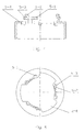
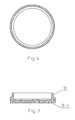
- the toothed member 9 As shown in Fig. 2, there is a toothed member 9 formed between the front sleeve 6 and the nut jacket 5 , the toothed member 9 has a cylinder shape and connected into the front portion of the chuck body 1 in the manner of interference fit.
- There are ratchets formed on the toothed member 9 more particularly, a plurality of angled teeth are formed in the inner circumference wall of the lower portion of the toothed member 9 as shown in Figs 6 and 7, which can engage with detents of elastic elements (which will be described hereinafter).
- a plurality of grooves are provided in the inner circumference wall of the front sleeve 6 , the grooves include first positioning grooves 6-1 , i.e.
- second positioning grooves 6-2 i.e. the positioning grooves for a fastened state of the front sleeve 6
- third positioning groove 6-3 i.e. the positioning grooves for locking of the front sleeve 6 .
- a plurality of elastic members are formed on the front end portion of the nut jacket 5, which is integral with the nut jacket 5.
- Each of the elastic members has elastic positioning pawl 5-1 , locking detent 5-2 , and elastic locking positioning pawl 5-3 .
- On the upper end portion of the nut jacket 5 there are key slots 5-4 formed in the radial direction, which are engaged with the keys of the front sleeve 6 respectively to transmit the torque to the nut jacket 5 and the nut 3 , as shown in Fig. 3.
- the front sleeve 6 and the nut jacket 5 can rotate with respect to each other within a predetermined angle.
- the nut jacket 5 of the locking drill chuck effects as two functions, one is to fixedly connect to the nut 3 to be incorporated with each other, the another function is to let the locking detents of the nut jacket 5 engage the teeth, i.e. ratchets, of the toothed member 9 directly, so that the unique locking function of the locking drill chuck can be achieved, therefore the locking drill chuck can be used in a reliable operating state.
- the toothed member 9 is fixedly connected to the front portion of the chuck body 1 , the locking detents 5-2 engage the teeth of the toothed member 9 , the front sleeve 6 is rotatable with respect to the nut jacket 5 within a predetermined circumferential gap, axial grooves that match the elastic positioning pawls 5-1 and elastic locking positioning pawls 5-3 are formed at the inner circumference wall of the small opening end of the front sleeve 6 .
- the front sleeve 6 carries the nut jacket 5 and further the nut 3 to rotate as the front sleeve 6 is turned, therefore the jaws 4 move forward to reach the drill tool to be fastened, meanwhile the elastic locking positioning pawls 5-3 that is integral with the elastic positioning pawls 5-1 are depressed, the locking detents 5-2 are in the state of non-locking and turned synchronously by the front sleeve 6 .
- the front sleeve 6 will turn once the force applied to the front sleeve 6 more than the elastic force of the elastic positioning pawls 5-1 of the nut jacket 5 , the elastic positioning pawls 5-1 disengages from the first positioning grooves 6-1 and moves to the second positioning grooves 6-2 of the front sleeve 6 , the elastic locking positioning pawls 5-3 moves from the non-locking grooves of the front sleeve 6 to the third grooves 6-3 , at the same time, driving keys of the front sleeve 6 move to another clamping side of the key slots of the nut jacket 5 , the locking detents 5-2 are released and come into engagement with the teeth of the toothed member 9 in the front portion of the chunk body 1 to form a locking state of
- the nut 3 With the increase of the force applied to the front sleeve 6 , the nut 3 will turn forward along with the nut jacket 5 when the force reaches to a certain degree, which causes the locking detents 5-2 in the locking state to slide and ticks from one teeth of the toothed member 9 to another teeth, the nut 3 moves until the input torque applied to the front sleeve 6 increase to a certain degree, thereby the locking detents 5-2 are locked in the one way teeth grooves of the toothed member 9 .
- the locking drill chuck can be used with high reliable locking state due to the engagement of the plurality of detents of the nut jacket 5 with the teeth of the toothed member 9 .
- the front sleeve 6 When loosening, the front sleeve 6 is turned in a reverse direction, the second positioning grooves 6-2 in the inner circumference wall of the front sleeve 6 carry the elastic positioning pawls 5-1 , meanwhile the elastic positioning pawls 5-2 at the opposite side of the pawls 5-1 of the nut jacket 5 are in locking state to prevent from loosening.
- the locking drill chuck according to the present invention has a simple and compact structure, high working stability, convenience of operation, and high reliability of self-locking capability. It can be used for all kinds of drill tools, especially used for impact drill tools.
Applications Claiming Priority (2)
| Application Number | Priority Date | Filing Date | Title |
|---|---|---|---|
| CN03269091U | 2003-07-17 | ||
| CN03269091.6U CN2633481Y (zh) | 2003-07-17 | 2003-07-17 | 锁紧式钻夹头 |
Publications (1)
| Publication Number | Publication Date |
|---|---|
| EP1498201A1 true EP1498201A1 (fr) | 2005-01-19 |
Family
ID=33459854
Family Applications (1)
| Application Number | Title | Priority Date | Filing Date |
|---|---|---|---|
| EP04077044A Withdrawn EP1498201A1 (fr) | 2003-07-17 | 2004-07-15 | Mandrin de forage autoserrant |
Country Status (3)
| Country | Link |
|---|---|
| US (1) | US7249770B2 (fr) |
| EP (1) | EP1498201A1 (fr) |
| CN (1) | CN2633481Y (fr) |
Cited By (2)
| Publication number | Priority date | Publication date | Assignee | Title |
|---|---|---|---|---|
| GB2426944A (en) * | 2005-06-09 | 2006-12-13 | Jacobs Chuck Mfg Co | Keyless chuck with ratchet tightening mechanism |
| US7249770B2 (en) * | 2003-07-17 | 2007-07-31 | Shandong Weida Machinery Co., Ltd. | Locking drill chuck |
Families Citing this family (15)
| Publication number | Priority date | Publication date | Assignee | Title |
|---|---|---|---|---|
| JP4294945B2 (ja) * | 2002-12-06 | 2009-07-15 | ユキワ精工株式会社 | チャック装置 |
| US20060261563A1 (en) * | 2003-03-25 | 2006-11-23 | Guimo Yang | Self-locking drill chuck |
| CN2602857Y (zh) * | 2003-03-25 | 2004-02-11 | 山东威达机械股份有限公司 | 自锁式钻夹头 |
| JP4616576B2 (ja) * | 2004-04-20 | 2011-01-19 | ユキワ精工株式会社 | チャック装置 |
| US7451990B2 (en) * | 2004-04-29 | 2008-11-18 | Jacobs Chuck Manufacturing Company | Chuck with torque indicator |
| CN2715890Y (zh) * | 2004-08-03 | 2005-08-10 | 山东威达机械股份有限公司 | 带响自锁式钻夹头 |
| US7837200B2 (en) | 2005-07-01 | 2010-11-23 | Jacobs Chuck Manufacturing Company | Chuck |
| CN100434212C (zh) * | 2006-07-11 | 2008-11-19 | 胡振钱 | 具有防冲击松动机构的无匙钻夹头 |
| WO2008064523A1 (fr) * | 2006-11-30 | 2008-06-05 | Zhenqian Hu | Mandrin de perceuse présentant une fonction anti-desserrage |
| US8057134B2 (en) | 2007-06-26 | 2011-11-15 | Techtronic Power Tools Technology Limited | Chuck assembly |
| US8075229B2 (en) * | 2007-06-26 | 2011-12-13 | Techtronic Power Tools Technology Limited | Multi-speed drill and chuck assembly |
| JP2011079113A (ja) * | 2009-10-09 | 2011-04-21 | Tenryu Saw Mfg Co Ltd | 円板状回転工具の取付け装置 |
| CN107138774B (zh) * | 2017-06-23 | 2023-11-28 | 浙江三鸥机械股份有限公司 | 一种自锁式钻夹头 |
| CN108581832A (zh) * | 2018-04-10 | 2018-09-28 | 浙江朝鸿机械有限公司 | 一种棘爪式内楔卡头 |
| CN109940200A (zh) * | 2019-04-28 | 2019-06-28 | 柳尧亭 | 离合装置、钻夹头、动力工具和钻夹头双向转动的方法 |
Citations (1)
| Publication number | Priority date | Publication date | Assignee | Title |
|---|---|---|---|---|
| US6390481B1 (en) * | 2000-03-10 | 2002-05-21 | Power Tool Holders Incorporated | Locking chuck |
Family Cites Families (11)
| Publication number | Priority date | Publication date | Assignee | Title |
|---|---|---|---|---|
| DE4438991C5 (de) * | 1994-10-31 | 2009-07-30 | Röhm Gmbh | Bohrfutter |
| EP0785041B1 (fr) * | 1996-01-17 | 2001-02-28 | Röhm GmbH | Mandrin porte-foret |
| WO1998040182A1 (fr) * | 1997-03-12 | 1998-09-17 | Shandong Weida Machine Tool Tools Group Corporation | Mandrin de serrage manuel |
| US6572310B2 (en) * | 2000-12-08 | 2003-06-03 | Power Tool Holders Incorporated | Self-cleaning drill chuck |
| CN1217762C (zh) * | 2001-06-10 | 2005-09-07 | 山东威达机械股份有限公司 | 自锁钻夹头 |
| CN1220569C (zh) * | 2001-06-10 | 2005-09-28 | 山东威达机械股份有限公司 | 自紧钻夹头 |
| CN2582790Y (zh) * | 2002-11-25 | 2003-10-29 | 山东威达机械股份有限公司 | 自锁钻夹头 |
| CN2633481Y (zh) * | 2003-07-17 | 2004-08-18 | 山东威达机械股份有限公司 | 锁紧式钻夹头 |
| US20050087937A1 (en) * | 2003-10-22 | 2005-04-28 | Wenhua Zhou | Lock type manually tightened chuck |
| CN2715890Y (zh) * | 2004-08-03 | 2005-08-10 | 山东威达机械股份有限公司 | 带响自锁式钻夹头 |
| US7000926B1 (en) * | 2004-10-29 | 2006-02-21 | Zhe Jiang San Ou Machinery Co.Ltd | Manually tightened drill chuck |
-
2003
- 2003-07-17 CN CN03269091.6U patent/CN2633481Y/zh not_active Expired - Fee Related
-
2004
- 2004-07-15 EP EP04077044A patent/EP1498201A1/fr not_active Withdrawn
- 2004-07-16 US US10/892,976 patent/US7249770B2/en active Active
Patent Citations (1)
| Publication number | Priority date | Publication date | Assignee | Title |
|---|---|---|---|---|
| US6390481B1 (en) * | 2000-03-10 | 2002-05-21 | Power Tool Holders Incorporated | Locking chuck |
Cited By (10)
| Publication number | Priority date | Publication date | Assignee | Title |
|---|---|---|---|---|
| US7249770B2 (en) * | 2003-07-17 | 2007-07-31 | Shandong Weida Machinery Co., Ltd. | Locking drill chuck |
| GB2426944A (en) * | 2005-06-09 | 2006-12-13 | Jacobs Chuck Mfg Co | Keyless chuck with ratchet tightening mechanism |
| US7472913B2 (en) | 2005-06-09 | 2009-01-06 | Jacobs Chuck Manufacturing Company | Drill chuck |
| US7748719B2 (en) | 2005-06-09 | 2010-07-06 | Jacobs Chuck Manufacturing Company | Drill chuck |
| GB2426944B (en) * | 2005-06-09 | 2010-09-22 | Jacobs Chuck Mfg Co | Drill chuck |
| US7997587B2 (en) | 2005-06-09 | 2011-08-16 | Jacobs Chuck Manufacturing Company | Drill chuck |
| US8191902B2 (en) | 2005-06-09 | 2012-06-05 | Jacobs Chuck Manufacturing Company | Drill chuck |
| US8511692B2 (en) | 2005-06-09 | 2013-08-20 | Jacobs Chuck Manufacturing Company | Drill chuck |
| US8695991B2 (en) | 2005-06-09 | 2014-04-15 | Apex Brands, Inc. | Drill chuck |
| US9221105B2 (en) | 2005-06-09 | 2015-12-29 | Apex Brands, Inc. | Drill chuck |
Also Published As
| Publication number | Publication date |
|---|---|
| US7249770B2 (en) | 2007-07-31 |
| US20050023776A1 (en) | 2005-02-03 |
| CN2633481Y (zh) | 2004-08-18 |
Similar Documents
| Publication | Publication Date | Title |
|---|---|---|
| US7249770B2 (en) | Locking drill chuck | |
| US7481608B2 (en) | Rotatable chuck | |
| US7124839B2 (en) | Impact driver having an external mechanism which operation mode can be selectively switched between impact and drill modes | |
| US7128324B2 (en) | Hammerlock chuck | |
| US7478979B2 (en) | Rotatable chuck | |
| EP1834735B1 (fr) | Outil électrique à limitation de couple | |
| US6418821B1 (en) | Working tool | |
| US7757374B2 (en) | Keyless chuck with automatic and manual locking | |
| US7296803B2 (en) | Chuck | |
| US7125021B2 (en) | Self-locking drill chuck | |
| US6843485B2 (en) | Chuck device | |
| US20230045384A1 (en) | Attachment mechanism for a power tool | |
| US20060027979A1 (en) | Lockable chuck | |
| EP2087958B1 (fr) | Mandrin auto-bloquant | |
| EP1324847A1 (fr) | Mandrin et entrainement mecanique a ensemble interface ameliore | |
| EP1989023B1 (fr) | Mecanisme d'entrainement a cliquet tridirectionnel | |
| US7520512B2 (en) | Drill chuck | |
| JP2001105333A (ja) | 作業工具用ソケット | |
| US20070000356A1 (en) | Ratcheting device | |
| US4008636A (en) | Ratchet wrench | |
| WO2003037568A1 (fr) | Cle | |
| CN113766987A (zh) | 具有锁定离合器的夹头 | |
| JPH02172604A (ja) | 締め付け具 |
Legal Events
| Date | Code | Title | Description |
|---|---|---|---|
| PUAI | Public reference made under article 153(3) epc to a published international application that has entered the european phase |
Free format text: ORIGINAL CODE: 0009012 |
|
| AK | Designated contracting states |
Kind code of ref document: A1 Designated state(s): AT BE BG CH CY CZ DE DK EE ES FI FR GB GR HU IE IT LI LU MC NL PL PT RO SE SI SK TR |
|
| AX | Request for extension of the european patent |
Extension state: AL HR LT LV MK |
|
| AKX | Designation fees paid | ||
| 17P | Request for examination filed |
Effective date: 20050705 |
|
| RBV | Designated contracting states (corrected) |
Designated state(s): AT BE BG CH CY CZ DE DK EE ES FI FR GB GR HU IE IT LI LU MC NL PL PT RO SE SI SK TR |
|
| REG | Reference to a national code |
Ref country code: DE Ref legal event code: 8566 |
|
| 17Q | First examination report despatched |
Effective date: 20070115 |
|
| STAA | Information on the status of an ep patent application or granted ep patent |
Free format text: STATUS: THE APPLICATION IS DEEMED TO BE WITHDRAWN |
|
| 18D | Application deemed to be withdrawn |
Effective date: 20080201 |