EP1497034B1 - A self-cleaning spray nozzle - Google Patents
A self-cleaning spray nozzle Download PDFInfo
- Publication number
- EP1497034B1 EP1497034B1 EP03767489A EP03767489A EP1497034B1 EP 1497034 B1 EP1497034 B1 EP 1497034B1 EP 03767489 A EP03767489 A EP 03767489A EP 03767489 A EP03767489 A EP 03767489A EP 1497034 B1 EP1497034 B1 EP 1497034B1
- Authority
- EP
- European Patent Office
- Prior art keywords
- spray nozzle
- carrier
- temperature
- composition
- tube
- Prior art date
- Legal status (The legal status is an assumption and is not a legal conclusion. Google has not performed a legal analysis and makes no representation as to the accuracy of the status listed.)
- Expired - Lifetime
Links
Images


Classifications
-
- B—PERFORMING OPERATIONS; TRANSPORTING
- B05—SPRAYING OR ATOMISING IN GENERAL; APPLYING FLUENT MATERIALS TO SURFACES, IN GENERAL
- B05B—SPRAYING APPARATUS; ATOMISING APPARATUS; NOZZLES
- B05B7/00—Spraying apparatus for discharge of liquids or other fluent materials from two or more sources, e.g. of liquid and air, of powder and gas
- B05B7/02—Spray pistols; Apparatus for discharge
- B05B7/12—Spray pistols; Apparatus for discharge designed to control volume of flow, e.g. with adjustable passages
- B05B7/1209—Spray pistols; Apparatus for discharge designed to control volume of flow, e.g. with adjustable passages the controlling means for each liquid or other fluent material being manual and interdependent
-
- B—PERFORMING OPERATIONS; TRANSPORTING
- B05—SPRAYING OR ATOMISING IN GENERAL; APPLYING FLUENT MATERIALS TO SURFACES, IN GENERAL
- B05B—SPRAYING APPARATUS; ATOMISING APPARATUS; NOZZLES
- B05B15/00—Details of spraying plant or spraying apparatus not otherwise provided for; Accessories
- B05B15/50—Arrangements for cleaning; Arrangements for preventing deposits, drying-out or blockage; Arrangements for detecting improper discharge caused by the presence of foreign matter
- B05B15/55—Arrangements for cleaning; Arrangements for preventing deposits, drying-out or blockage; Arrangements for detecting improper discharge caused by the presence of foreign matter using cleaning fluids
-
- B—PERFORMING OPERATIONS; TRANSPORTING
- B05—SPRAYING OR ATOMISING IN GENERAL; APPLYING FLUENT MATERIALS TO SURFACES, IN GENERAL
- B05B—SPRAYING APPARATUS; ATOMISING APPARATUS; NOZZLES
- B05B7/00—Spraying apparatus for discharge of liquids or other fluent materials from two or more sources, e.g. of liquid and air, of powder and gas
- B05B7/02—Spray pistols; Apparatus for discharge
- B05B7/04—Spray pistols; Apparatus for discharge with arrangements for mixing liquids or other fluent materials before discharge
- B05B7/0416—Spray pistols; Apparatus for discharge with arrangements for mixing liquids or other fluent materials before discharge with arrangements for mixing one gas and one liquid
- B05B7/0441—Spray pistols; Apparatus for discharge with arrangements for mixing liquids or other fluent materials before discharge with arrangements for mixing one gas and one liquid with one inner conduit of liquid surrounded by an external conduit of gas upstream the mixing chamber
- B05B7/0475—Spray pistols; Apparatus for discharge with arrangements for mixing liquids or other fluent materials before discharge with arrangements for mixing one gas and one liquid with one inner conduit of liquid surrounded by an external conduit of gas upstream the mixing chamber with means for deflecting the peripheral gas flow towards the central liquid flow
-
- B—PERFORMING OPERATIONS; TRANSPORTING
- B05—SPRAYING OR ATOMISING IN GENERAL; APPLYING FLUENT MATERIALS TO SURFACES, IN GENERAL
- B05B—SPRAYING APPARATUS; ATOMISING APPARATUS; NOZZLES
- B05B7/00—Spraying apparatus for discharge of liquids or other fluent materials from two or more sources, e.g. of liquid and air, of powder and gas
- B05B7/02—Spray pistols; Apparatus for discharge
- B05B7/06—Spray pistols; Apparatus for discharge with at least one outlet orifice surrounding another approximately in the same plane
- B05B7/062—Spray pistols; Apparatus for discharge with at least one outlet orifice surrounding another approximately in the same plane with only one liquid outlet and at least one gas outlet
- B05B7/066—Spray pistols; Apparatus for discharge with at least one outlet orifice surrounding another approximately in the same plane with only one liquid outlet and at least one gas outlet with an inner liquid outlet surrounded by at least one annular gas outlet
Definitions
- the present invention relates to a self-cleaning spray nozzle and in particular to a self-cleaning spray nozzle for use in an apparatus for the preparation of a particulate material by a controlled agglomeration method, i.e. a method for controlled growth of particle size.
- the apparatus is especially suitable for use in the preparation of pharmaceutical compositions containing a therapeutically and/or prophylactically active substance which has a relatively low aqueous solubility and/or which is subject to chemical decomposition.
- the controlled agglomeration method is disclosed in International Patent Application No. PCT/DK02/00472 assigned to the present Applicant.
- the method enables preparation of pharmaceutical compositions for oral use that release the active substance from the composition in a suitable manner to enable an absorption of the active substance into the circulatory system.
- a controlled agglomeration process may for example be carried out in a high or low shear mixer or in a fluid bed.
- a carrier or a carrier composition is sprayed on a second composition, which is loaded into the mixer or the fluid bed.
- the carrier or the carrier composition is heated to a temperature above the melting point of the carrier and/or the carrier composition while the second composition is not subjected to any heating and thus, stays at ambient temperature.
- the difference in temperature between the carrier and the second composition makes the carrier solidify rapidly which in turn leads to a controlled growth of the particle size.
- the inventors have found that by employing such conditions it is possible to control the agglomeration process so that the growth in particle size is controlled.
- carrier is used as an abbreviation of the term “carrier composition”.
- a carrier composition comprises one or more carriers, optionally together with one or more other ingredients.
- the carrier composition may comprise a mixture of hydrophilic and/or hydrophobic carriers and/or surfactants.
- the carrier composition may also comprise one or more therapeutically and/or prophylactically active substances and/or one or more pharmaceutically acceptable excipients.
- DE 27 46 489 discloses a device and method for manufacture of microcapsules with liquid or solid filling by spray drying. Different parameters of the device are fixed providing a limited range of use.
- WO 03/051505 discloses a spray unit coating for coating of particles, the spray unit having a core with a central pipe for the transfer of particles and two side pipes for the transfer of coating solution.
- the spray nozzle should neither be susceptible to depositions of fluidised particles, carrier droplets, nor solidified carrier particles.
- a spray nozzle comprising a central tube with a central passage for supply of a liquid, the passage terminating in an orifice for discharge of the liquid, a second tube surrounding the central tube whereby a first passage is defined between the central tube and the second tube for supply of primary air, a nozzle cone positioned at the end of the second tube and defining the outer periphery of a first discharge gap of the first passage, causing air supplied through the first passage to be mixed with the liquid to provide a liquid/air spray, a third tube surrounding the second tube whereby a second passage is defined between the second and the third tube for supply of secondary air, and a jacket positioned at the end of the third tube and defining the outer periphery of a second discharge gap of the second passage.
- an apparatus for controlled agglomeration, comprising the spray nozzle according to the present invention, and a fluid bed for fluidisation of a second composition.
- the spray nozzle may be mounted at the top of the fluid bed, at the side of the fluid bed or at the bottom of the fluid bed as is well known in the art.
- the fluid bed may e.g. be a roto fluid bed, a Wurster fluid bed, a Kugel coater, a Pharma Steel Phast fluid bed, etc.
- an apparatus comprising the spray nozzle and an intensive mixer for mixing of the second composition.
- the intensive mixer may be a high shear mixer, a low shear mixer, a horizontal mixer, a vertical mixer etc.
- an apparatus comprising the spray nozzle mounted in a spray dryer, e.g. mounted at the top of the spray dryer or mounted at the bottom of the spray dryer.
- the second composition may have a temperature of at the most a temperature corresponding to a melting point of a carrier, such as a temperature of at least about 2 °C, at least about 5 °C or at least about 10 °C lower than the melting point of the carrier.
- the spray nozzle is mounted for spraying a first composition comprising the carrier in liquid form, on the second composition fluidised in the fluid bed or mixed in the intensive mixer, or the spray nozzle is mounted for spray drying the first composition in a spray dryer.
- a temperature and pressure controlled tank containing the first composition is connected to the central passage for supply of the first composition at a temperature above the melting point of the carrier. Further, a first temperature controlled pressurised air supply that is connected to the first passage for supplying temperature controlled primary air to the spray nozzle, and a second temperature controlled pressurised air supply that is connected to the second passage for supplying temperature controlled secondary air to the spray nozzle.
- the spray nozzle according to the present invention is situated in a complex air flow that may transport particles or droplets of the first composition and particles of the second composition to surfaces of the spray nozzle.
- the temperature controlled secondary air supplied from the second discharge gap of the spray nozzle inhibits and substantially prevents deposition of such particles on the surfaces of the spray nozzle.
- the spray nozzle sustains spraying throughout the required process time.
- the spray angle may further be controlled by appropriate adjustment of the secondary airflow.
- the secondary airflow may be utilised to increase the pressure at the orifice whereby the spray angle of the spray cone is decreased.
- the spray angle may be set to be less than 20°, preferably less than 15°, more preferred less than 10°, even more preferred less than 5°. A low value of the spray cone is preferred minimising the amount of sprayed material impinging on container walls.
- the spray nozzle is well suited for spraying a high temperature melt in any environment.
- the advantageous cleaning effect of the secondary air is caused by the secondary airflow as such in combination with heating by the secondary air of the surfaces.
- the optimum temperature range is related to the melting point of the carrier.
- the carrier may have a melting point of about 5 °C or more such as, e.g., about 10 °C or more, about 20°C or more or about 25 °C or more.
- the temperature of the secondary air must be sufficiently low to cool the surface of the nozzle tip to the lower end of the melting temperature range of the carrier. If the temperature is higher, adhesion of liquid droplets might result in deposits of solid second composition material. If the temperature is lower, liquid droplets might solidify and act as seeding for build up of deposits.
- proper atomisation of the first composition requires that the primary air temperature at the nozzle orifice exceeds or at least corresponds to the melting temperature of the carrier. Because of the rapid temperature drop with distance to the nozzle orifice, a high temperature of the primary air is preferred. The upper temperature limit is defined by the boiling point of the carrier. However, the primary air heats the nozzle and thereby the outer surfaces of the nozzle, and therefore the heat insulation properties of the nozzle influence the maximum obtainable primary air temperature.
- the sizes of the nozzle orifice and the first and second discharge gaps and their mutual positions are selected for optimum spray formation and self-cleaning.
- the spray angle of the formed spray cone is selected to a low value so that the spray does not impinge on container walls.
- the first discharge gap may be generally concentric with the orifice, and positioned at a distance upstream in relation to the orifice.
- the second discharge gap may be generally concentric with the first discharge gap and positioned at a distance upstream in relation to the first discharge gap.
- the diameter of the nozzle orifice may be between 0,1 mm and 3 mm, preferably between 0,5 mm and 2 mm.
- the width of the first discharge gap may be less than 3 mm, preferably between 0,1 mm and 0,4 mm.
- the width of the second discharge gap may be less than 3 mm, preferably between 0,1 mm and 0,4 mm.
- the spray nozzle comprises a nozzle tip comprising the orifice and a part of the central passage.
- the nozzle tip may be removably positioned in the spray nozzle facilitating maintenance, such as cleaning and sterilization.
- the spray nozzle comprises a central tube, the interior of which defines the central passage.
- the central tube may be made of stainless steel, such as acid resisting steel, e.g. AISI 316, or duplex steel, e.g. SAF 2205, etc.
- the central tube is a flexible hose for easy instalment of the hose in the spray nozzle.
- the hose may be made of a heat-resistant plastic, such as PTFE, silicone, PVC, polyethylene, Teflon ®, polyetheretherketone (PEEK), fluorerscent, etc, and one end of the hose may be provided with a thread for fastening of the hose to the nozzle tip.
- the central tube is constructed with a Teflon ® inner liner reinforced with a protective cover, e.g. a stainless steel cover, or a flexible cover, such as a braided cover of stainless steel, or a plastic cover.
- the central tube is removably positioned in the spray nozzle and may be discarded after use whereby cleaning and sterilization of the spray nozzle is facilitated.
- the central tube and the nozzle tip form a unit that is removably positioned in the spray nozzle and may be discarded after use whereby cleaning and sterilization of the spray nozzle is facilitated. Cumbersome and time consuming cleaning of the central tube and nozzle tip between batch productions is hereby completely eliminated.
- the spray nozzle may comprise a second tube surrounding the central tube, the first passage being defined between the central tube and the second tube.
- the second tube is made of stainless steel, such as AISI 316 or SAF 2205.
- the spray nozzle may comprise a third tube surrounding the second tube, the second passage being defined between the second and the third tube.
- the third tube is made of stainless steel, such as AISI 316 or SAF 2205.
- a nozzle cone may be provided that is positioned at the end of the second tube, defining the periphery of the first discharge gap.
- the nozzle cone is made of plastic, such as polycarbonate, or nylon, etc. More preferred, the nozzle cone is made of stainless steel, such as AISI 316 or SAF 2205.
- the nozzle cone may be adjustably positioned at the end of the second tube for adjustment of the size of the first discharge gap for optimum spray formation. Further, the nozzle cone may be removably attached to the second tube for easy maintenance and repair of the spray nozzle.
- the nozzle cone may comprise a thread for engagement with a corresponding thread provided at the second tube.
- the position of the first discharge gap in relation to the nozzle orifice may be adjusted by rotation of the nozzle cone in relation to the second tube, the thread pitch determining the positional adjustment as a function of the angle of rotation.
- the positional change of the first discharge gap also changes the width of the first discharge gap.
- a scale may be provided on the second tube and a mark on the nozzle cone, or vice versa, so that a desired first discharge gap width may be set by appropriate positioning of the marker in relation to the scale by corresponding rotation of the nozzle cone.
- a jacket may be provided that is positioned at the end of the third tube and define the periphery of the second discharge gap. Further, the jacket may be adjustably positioned at the end of the third tube for adjustment of the size of the second discharge gap for optimum self-cleaning performance. Further, the jacket may be removably attached to the third tube for easy maintenance and repair of the spray nozzle.
- the nozzle jacket may comprise a thread for engagement with a corresponding thread provided at the third tube.
- the position of the second discharge gap in relation to the first discharge gap may be adjusted by rotation of the nozzle jacket in relation to the third tube, the thread pitch determining the positional adjustment as a function of the angle of rotation.
- the positional change of the second discharge gap also changes the width of the second discharge gap.
- a scale may be provided on the third tube and a mark on the nozzle jacket, or vice versa, so that a desired second discharge gap width may be set by appropriate positioning of the marker in relation to the scale by corresponding rotation of the nozzle jacket.
- the jacket is tapered towards the second discharge gap so that during spraying the jacket substantially does not present any horizontal surfaces whereby deposition of substance on the spray nozzle is further minimised.
- the jacket may be made of stainless steel, such as AISI 316 or SAF 2205.
- the jacket is made of a hardened plastic material, such as Peek, etc to obtain a heat stable, non-sticky jacket that does not absorb moisture.
- different parts of the spray nozzle that are movably attached to each other, e.g. in a threaded engagement, as for example the nozzle cone and the second tube, are made of different types of stainless steel, such as AISI 316 and SAF 2205, respectively, to avoid reaming of the materials by moving of the parts in relation to each other.
- the spray nozzle may be provided with a teflon coated surface, e.g. the jacket may be teflon coated, the nozzle cone may be teflon coated, etc, for further inhibition of deposition of particles on the respective surfaces.
- the spray nozzle may be angled or bend so that it comprises a first part that extends along a first axis, and a second part extending along a second axis that forms an angle ⁇ with the first axis.
- the angle ⁇ may be approximately equal to 90°, or less than 90°, such as approximately equal to 60° facilitating positioning of the spray nozzle in a shear mixer, or a fluid bed, etc.
- a member may be provided in the nozzle cone, the member having apertures or channels for passage of the primary air.
- the longitudinal axes of the apertures or channels may form an angle with a longitudinal axis of the second tube whereby a swirling flow is induced in the primary airflow.
- the swirling motion of the flow creates a vortex and a region of relatively low pressure whereby the spray angle is increased.
- the apparatus enables incorporation in a solid material of a high load of a carrier of a type that, e.g. due to its solubility properties, enables a high load of therapeutically and/or prophylactically active substances with a relatively low aqueous solubility.
- the carrier is normally solid or semi-solid and normally it has a sticky, oily or waxy character.
- the carrier may also be fluid at room temperature or even at temperature below 5 °C and in such cases it is contemplated that the apparatus is operated by employment of cooling of the second composition.
- the particulate material obtained by the novel apparatus has excellent properties with respect to flowability, bulk density, compactability and thus, it is suitable for use in the preparation of e.g. tablets.
- the particulate material may have a high load of a carrier of substantially sticky character the particulate material prepared has minimal, if any, adherence to tablet punches and/or dies during manufacture of tablets.
- the carrier is of a type which has a melting point of at least about 25 °C such as, e.g., at least about 30 °C at least about 35 °C or at least about 40 °C.
- the melting point may not be too high, thus, the carrier normally has a melting point of at the most about 300 °C such as, e.g., at the most about 250 °C, at the most about 200 °C, at the most about 150 °C or at the most about 100 °C. If the melting point is higher then it becomes very difficult to ensure maintenance of a sufficient high temperature during the delivery of the carrier to the spraying equipment necessary to provide the melted carrier in the form of a spray.
- a relatively high temperature may promote e.g. oxidation or other kind of degradation of the substance.
- the melting point is determined by DSC (Differential Scanning Calorimetry).
- the melting point is determined as the temperature at which the linear increase of the DSC curve intersects the temperature axis (see Fig. 6 for further details).
- Suitable carriers are generally substances, which are used in the manufacture of pharmaceuticals as so-called melt binders or solid solvents (in the form of solid dosage form), or as co-solvents or ingredients in pharmaceuticals for topical use.
- the carrier may be hydrophilic, hydrophobic and/or they may have surface-active properties.
- hydrophilic and/or hydrophobic carriers are suitable for use in the manufacture of a pharmaceutical composition comprising a therapeutically and/or prophylactically active substance that has a relatively low aqueous solubility and/or when the release of the active substance from the pharmaceutical composition is designed to be immediate or non-modified.
- Hydrophobic carriers are normally used in the manufacture of a modified release pharmaceutical composition.
- a suitable carrier examples include a hydrophilic carrier, a hydrophobic carrier, a surfactant or mixtures thereof.
- a suitable hydrophilic carrier is selected from the group consisting of: polyether glycols such as, e.g., polyethylene glycols, polypropylene glycols; polyoxyethylenes; polyoxypropylenes; poloxamers and mixtures thereof, or it may be selected from the group consisting of: xylitol, sorbitol, potassium sodium tartrate, sucrose tribehenate, glucose, rhamnose, lactitol, behenic acid, hydroquinon monomethyl ether, sodium acetate, ethyl fumarate, myristic acid, citric acid, Gelucire 50/13, other Gelucire types such as, e.g., Gelucire 44/14 etc., Gelucire 50/10, Gelucire 62/05, Sucro-ester 7, Sucro-ester 11, Sucro-ester 15, maltose, mannitol and mixtures thereof.
- polyether glycols such as, e.g., polyethylene glycols, polypropylene glyco
- a hydrophobic carrier for use in an apparatus of the invention may be selected from the group consisting of: straight chain saturated hydrocarbons, sorbitan esters, paraffins; fats and oils such as e.g., cacao butter, beef tallow, lard, polyether glycol esters; higher fatty acid such as, e.g.
- stearic acid myristic acid, palmitic acid, higher alcohols such as, e.g., cetanol, stearyl alcohol, low melting point waxes such as, e.g., glyceryl monostearate, hydrogenated tallow, myristyl alcohol, stearyl alcohol, substituted and/or unsubstituted monoglycerides, substituted and/or unsubstituted diglycerides, substituted and/or unsubstituted triglycerides, yellow beeswax, white beeswax, carnauba wax, castor wax, japan wax, acetylate monoglycerides; NVP polymers, PVP polymers, acrylic polymers, or a mixture thereof.
- alcohols such as, e.g., cetanol, stearyl alcohol, low melting point waxes such as, e.g., glyceryl monostearate, hydrogenated tallow, myristyl
- the carrier is a polyethylene glycol having an average molecular weight in a range of from about 400 to about 35,000 such as, e.g., from about 800 to about 35,000, from about 1,000 to about 35,000 such as, e.g., polyethylene glycol 1,000, polyethylene glycol 2,000, polyethylene glycol 3,000, polyethylene glycol 4,000, polyethylene glycol 5,000, polyethylene glycol 6000, polyethylene glycol 7,000, polyethylene glycol 8,000, polyethylene glycol 9,000 polyethylene glycol 10,000, polyethylene glycol 15,000, polyethylene glycol 20,000, or polyethylene glycol 35,000.
- polyethylene glycol may be employed with a molecular weight from about 35,000 to about 100,000.
- the carrier is polyethylene oxide having a molecular weight of from about 2,000 to about 7,000,000 such as, e.g. from about 2,000 to about 100,000, from about 5,000 to about 75,000, from about 10,000 to about 60,000, from about 15,000 to about 50,000, from about 20,000 to about 40,000, from about 100,000 to about 7,000,000 such as, e.g., from about 100,000 to about 1,000,000, from about 100,000 to about 600,000, from about 100,000 to about 400,000 or from about 100,000 to about 300,000.
- the carrier is a poloxamer such as, e.g. Poloxamer 188, Poloxamer 237, Poloxamer 338 or Poloxamer 407 or other block copolymers of ethylene oxide and propylene oxide such as the Pluronic® and/or Tetronic® series.
- Suitable block copolymers of the Pluronic® series include polymers having a molecular weight of about 3,000 or more such as, e.g. from about 4,000 to about 20,000 and/or a viscosity (Brookfield) from about 200 to about 4,000 cps such as, e.g., from about 250 to about 3,000 cps.
- Suitable examples include Pluronic® F38, P65, P68LF, P75, F77, P84, P85, F87, F88, F98, P103, P104, P105, F108, P123, F123, F127, 10R8, 17R8, 25R5, 25R8 etc.
- Suitable block copolymers of the Tetronic® series include polymers having a molecular weight of about 8,000 or more such as, e.g., from about 9,000 to about 35,000 and/or a viscosity (Brookfield) of from about 500 to about 45,000 cps such as, e.g., from about 600 to about 40,000. The viscosities given above are determined at 60 °C for substances that are pastes at room temperature and at 77 °C for substances that are solids at room temperature.
- the carrier may also be a sorbitan ester such as, e.g., sorbitan di-isostearate, sorbitan dioleate, sorbitan monolaurate, sorbitan monoisostearate, sorbitan monooleate, sorbitan monopalmitate, sorbitan monostearate, sorbitan sesqui-isostearate, sorbitan sesquioleate, sorbitan sesquistearate, sorbitan tri-isostearate, sorbitan trioleate, sorbitan tristearate or mixtures thereof.
- sorbitan ester such as, e.g., sorbitan di-isostearate, sorbitan dioleate, sorbitan monolaurate, sorbitan monoisostearate, sorbitan monooleate, sorbitan monopalmitate, sorbitan monostearate, sorbitan sesqui-isostearate, sorbitan sesquiole
- the carrier composition may of course comprise a mixture of different carriers such as, e.g., a mixture of hydrophilic and/or hydrophobic carriers.
- the carrier is a surfactant or a substance having surface-active properties. It is contemplated that such substances are involved in the wetting of e.g. slightly soluble active substance and thus, contributes to improved solubility characteristics of the active substance.
- surfactants are given in the following. In order to be suitable for use as a carrier, the criteria with respect to melting point and/or viscosity discussed herein must be fulfilled. However, the list below encompasses surfactants in general, because surfactants may also be added to the carrier composition in the form of pharmaceutically acceptable excipients.
- Suitable excipients for use in a carrier composition are surfactants such as, e.g., hydrophobic and/or hydrophilic surfactants as those disclosed in WO 00/50007 in the name of Lipocine, Inc. Examples on suitable surfactants are
- the concentration of the surfactant(s) is normally in a range of from about 0,1 -75% w/w such as, e.g., from about 0.1 to about 20% w/w, from about 0.1 to about 15% w/w, from about 0.5 to about 10% w/w, or alternatively, when applicable as a carrier or a part of the carrier composition from about 20 to about 75% w/w such as, e.g. from about 25 to about 70% w/w, from about 30 to about 60% w/w.
- Suitable excipients in a carrier composition may be solvents or semi-solid excipients like, e.g. propylene glycol, polyglycolised glycerides including Gelucire 44/14, complex fatty materials of plant origin including theobroma oil, carnauba wax, vegetable oils like e.g. almond oil, coconut oil, corn oil, cottonseed oil, sesame oil, soya oil, olive oil, castor oil, palm kernels oil, peanut oil, rape oil, grape seed oil etc., hydrogenated vegetable oils such as, e.g.
- solvents or semi-solid excipients like, e.g. propylene glycol, polyglycolised glycerides including Gelucire 44/14, complex fatty materials of plant origin including theobroma oil, carnauba wax, vegetable oils like e.g. almond oil, coconut oil, corn oil, cottonseed oil, sesame oil, soya oil, olive oil, castor oil, palm kernels oil, peanut
- additives in the carrier composition may be antioxidants like e.g. ascorbic acid, ascorbyl palmitate, butylated hydroxyanisole, butylated hydroxytoluene, hypophosphorous acid, monothioglycerol, potassium metabisulfite, propyl gallate, sodium formaldehylde sulfoxylate, sodium metabisulfite, sodium thiosulfate, sulfur dioxide, tocopherol, tocopherol acetate, tocopherol hemisuccinate, TPGS or other tocopherol derivatives, etc.
- the carrier composition may also contain e.g. stabilising agents.
- the concentration of an antioxidant and/or a stabilizing agent in the carrier composition is normally from about 0.1 % w/w to about 5% w/w.
- the requirements with respect to the melting point mentioned above normally also apply to the carrier composition, especially in those cases where a minor amount of water is included in the carrier composition.
- the carrier composition when the carrier composition is heated, the carrier composition may be in the form of two or more phases (e.g. two distinct liquid phases or a liquid phase comprising e.g. an active substance dispersed therein).
- the melting point is not a true melting point but merely a heating point where the carrier composition becomes in a liquid form, which is suitable for use in a spraying device. Often such a heating point will for practical purposes correspond to the melting point of the carrier itself.
- the total concentration of carrier(s) in the carrier composition is normally in a range of from about 5 to about 100% w/w such as, e.g., from about 10 to about 99.5% w/w, from about 15 to about 99% w/w, from about 15 to about 98% w/w, from about 15 to about 97% w/w, from about 20 to about 95% w/w such as at least about 25% w/w, at least about 30% w/w, at least about 35% w/w, at least about 40% w/w, at least about 45% w/w, at least about 50% w/w, at least about 55% w/w, at least about 60% w/w, at least about 65% w/w, at least about 70% w/w, at least about 75% w/w, at least about 80% w/w, at least about 85% w/w, at least about 90% w/w, at least about 95% w/w or at least about 98% w/w.
- the carrier is brought on liquid form by heating the carrier and/or the carrier composition to a temperature, which causes the carrier, and/or the carrier composition to melt, and the carrier in liquid form (i.e. as a solution or a dispersion) is sprayed on the second composition.
- the carrier in melted or liquidized form is sprayed on a second composition.
- the carrier should have a suitable viscosity. If the viscosity is too high, the carrier or carrier composition will be too "thick" and will have a tendency of adhering to the nozzle, which may result in that the delivery through the nozzle is stopped.
- a viscosity of the carrier and/or the carrier composition is suitably if the viscosity (Brookfield DV-III) is at the most about 800 mPas at a temperature of at the most 100 °C such as, e.g., at the most 700, at the most 600, at the most 500 mPas. In those cases where the melting point of the carrier is more than about 80 °C, the viscosity values mentioned above are at a temperature of about 40 °C above the melting point.
- the concentration of the carrier is from about 5 to about 95% w/w such as, e.g. from about 5 to about 90% w/w, from about 5 to about 85% w/w, from about 5 to about 80% w/w, from about 10 to about 75% w/w, from about 15 to about 75% w/w, from about 20 to abut 75% w/w, from about 25% to about 75% w/w, from about 30% to about 75% w/w. from about 35% to about 75% w/w, from about 25% to about 70% w/w, from about 30% to about 70% w/w, from about 35% to abut 70 % w/w. from about 40% to about 70% w/w, from about 45% to about 65% w/w or from about 45% to about 60% w/w.
- the concentration of the carrier in the particulate material obtained by an apparatus of the invention is from about 5 to about 95% v/v such as, e.g.
- a therapeutically and/or prophylactically active substance in the carrier or in the carrier composition.
- Suitable therapeutically and/or prophylactically active substances are discussed below.
- an apparatus it is not necessary to employ water or an aqueous medium e.g. together with a binder in order to build up agglomerates of a suitable size.
- the agglomeration suitably takes place under water-free or substantially water-free conditions.
- the apparatus is also very useful when active substances or other ingredients are employed which are susceptible to water (e.g. degradation under aqueous conditions).
- water or an aqueous medium may of course be incorporated in the carrier composition.
- the carrier composition normally is essentially non-aqueous, water may be present to a certain extent and then the concentration of water in the carrier composition is the most about 20% w/w water such as at the most about 15% w/w, at the most abut 10% w/w, at the most about 5% w/w or at the most about 2.5% w/w.
- the particulate material obtained by an apparatus according to the invention comprises a therapeutically and/or prophylactically active substance.
- the particulate matter may also or alternatively comprise a cosmetically active substance (i.e. a substance that is employed in cosmetic compositions).
- the active substance may be included in the carrier composition and/or in the second composition.
- a therapeutically and/or prophylactically active substance includes any biologically and/or physiologically active substance that has a function on an animal such as, e.g. a mammal like a human.
- the term includes drug substances, hormones, genes or gene sequences, antigen- comprising material, proteins, peptides, nutrients like e.g. vitamins, minerals, lipids and carbohydrates and mixtures thereof.
- the term includes substances that have utility in the treatment and/or preventing of diseases or disorders affecting animals or humans, or in the regulation of any animal or human physiological condition.
- the term also includes any biologically active substance which, when administered in an effective amount, has an effect on living cells or organisms.
- an apparatus according to the invention is especially suitable for use for the preparation of particulate material comprising an active substance that has an aqueous solubility at 25 °C and pH of 7.4 of at the most about 3 mg/ml such as, e.g., at the most about 2 mg/ml, at the most about 1 mg/ml, at the most about 750 ⁇ g/ml, at the most about 500 ML/ml, at the most about 250 ML/ml, at the most about 100 ML/ml, at the most about 50 ML/ml, at the most about 25 ML/ml, at the most about 20 ML/ml or at the most about 10 ML/ml.
- solubility of the active substance may be much lower such as, e.g., at the most about 1 ML/ml, at the most about 100 ng/ml, at the most about 75 ng/ml such as about 50 ng/ml.
- an apparatus according to the invention may advantageously be operated without employment of water or an aqueous medium.
- the apparatus is especially suitable for use for active substances that are degraded, decomposed or otherwise influenced by water.
- active substances suitable for use in a particulate material according to the invention are in principle any active substance such as, e.g. freely water soluble as well as more slightly or insoluble active substances.
- active substances suitable for use are e.g. antibacterial substances, antihistamines and decongestants, anti-inflammatory agents, antiparasitics, antivirals, local anesthetics, antifungals, amoebicidals or trichomonocidal agents, analgesics, antianxiety agents, anticlotting agents, antiarthritics, antiasthmatics, antiarthritic, anticoagulants, anticonvulsants, antidepressants, antidiabetics, antiglaucoma agents, antimalarials, antimicrobials, antineoplastics, antiobesity agents, antipsychotics, antihypertensives, antitussives, auto-immune disorder agents, anti-impotence agents, anti-Parkinsonism agents, anti-Alzheim
- Anti-inflammatory drugs like e.g. ibuprofen, indometacin, naproxen, nalophine;
- Anti-Parkinsonism agents like e.g. bromocriptine, biperidin, benzhexol, benztropine etc.
- Antidepressants like e.g. imipramine, nortriptyline, pritiptyline, etc.
- Antibiotics like e.g. clindamycin, erythomycin, fusidic acid, gentamicin, mupirocine, amfomycin, neomycin, metronidazol, sulphamethizole, bacitracin, framycetin, polymyxin B, acitromycin etc,
- Antifungal agents like e.g. miconazol, ketoconaxole, clotrimazole, amphotericin B, nystatin, mepyramin, econazol, fluconazol, flucytocine, griseofulvin, bifonazole, amorofine, mycostatin, itrconazole, terbenafine, terconazole, tolnaftate etc.
- Antimicrobial agents like e.g. metronidazol, tetracyclines, oxytetracylines, peniciilins etc.
- Antiemetics like e.g. metoclopramide, droperidol, haloperidol, promethazine etc.
- Antihistamines like e.g. chlorpheniramine, terfenadine, triprolidine etc.
- Antimigraine agents like e.g. dihydroergotamine, ergotamine, pizofylline etc.
- Coronary, cerebral or peripheral vasodilators like e.g. nifedipine, diltiazem etc.
- Antianginals such as, e.g., glyceryl nitrate, isosorbide dinitrate, molsidomine, verapamil etc.
- Calcium channel blockers like e.g. verapamil, nifedipine, diltiazem, nicardipine etc.
- Hormonal agents like e.g. estradiol, estron, estriol, polyestradiol, polyestriol, dienestrol, diethylstilbestrol, progesterone, dihydroprogesterone, cyprosterone, danazol, testosterone etc.
- Contraceptive agents like e.g. ethinyl estradiol, lynestrenol, etynodiol, norethisterone, mestranol, norgestrel, levonorgestrel, desodestrel, medroxyprogesterone etc.
- Antithrombotic agents like e.g. heparin, warfarin etc.
- Diuretics like e.g. hydrochlorothiazide, flunarizine, minoxidil etc.
- Antihypertensive agents like e.g. propanolol, metoprolol, clonidine, pindolol etc.
- Corticosteroids like e.g. beclomethasone, betamethasone, betamethasone-17-valerate, betamethasone-dipropionate, clobetasol, clobetasol-17-butyrate, clobetasol-propionate, desonide, desoxymethasone, dexamethasone, diflucortolone, flumethasone, flumethasone-pivalte, fluocinolone acetonide,fluocinoide, hydrocortisone, hydrocortisone-17-butyrate, hydrocortisonebuteprate,methylprednisolone, triamcinolone acetonide, hacinonide, fluprednide acetate, alklometasone-dipropionate, fluocortolone, fluticason-propionte, mometasone-furate, desoxymethasone, diflurason-diacetate, halquinol,
- Dermatological agents like e.g. nitrofurantoin, dithranol, clioquinol, hydroxyquinoline, isotretionin, methoxsalen, methotrexate, tretionin, trioxalen, salicylic acid, penicillamine etc.
- Steroids like e.g. estradiol, progesterone, norethindrone, levonorgestrel, ethynodiol, levonorgestrol, norgestimate, gestanin, desogestrel, 3-keton-desogesterel, demegestone, promethoestrol, testosterone, spironolactone and esters thereof etc.
- Nitro compounds like e.g. amyl nitrates, nitroglycerine and isosorbide nitrate etc.
- Opioids like e.g. morphine, buprenorphine, oxymorphone, hydromorphone, codeine, tramadol etc.
- Prostaglandins such as, e.g., a member of the PGA, PGB, PGE or PGF series such as, e.g. minoprostol, dinoproston, carboprost, eneprostil etc.
- Peptides like e.g. growth hormone releasing factors, growth factors (e.g. epidermal growth factor (EGF), nerve growth factor (NGF), TGF, PDGF, insulin growth factor (IGF), fibroblast growth factor (aFGF, bFGF etc.), somatostatin, calcitonin, insulin, vasopressin, interferons, IL-2 etc., urokinase, serratiopeptidase, superoxide dismutase, thyrotropin releasing hormone, lutenizing hormone releasing hormone (LH-RH), corticotrophin releasing hormone, growth hormone releasing hormone (GHRH), oxytocin, erythropoietin (EPO), colony stimulating factor (CSF) etc.
- growth factors e.g. epidermal growth factor (EGF), nerve growth factor (NGF), TGF, PDGF, insulin growth factor (IGF), fibroblast growth factor (aFGF, bFGF etc.
- the amount of active substance incorporated in a particulate material may be selected according to known principles of pharmaceutical formulation.
- the dosage of the active substance present in a particulate material according to the invention depends inter alia on the specific drug substance, the age and condition of the patient and of the disease to be treated.
- a particulate material according to the invention may comprise a cosmetically active ingredient and/or a food ingredient.
- a cosmetically active ingredient and/or a food ingredient.
- Specific examples include vitamins, minerals, vegetable oils, hydrogenated vegetable oils, etc.
- the carrier or carrier composition is sprayed on a second composition.
- the second composition should initially have a temperature which is at least about 10 °C such as, e.g., at least about 15 °C, at least about 20 °C, at least about 25 °C, or at least about 30 °C below the melting point of the carrier or carrier composition (or, as discussed above, the heating point of the carrier composition).
- a temperature difference of at least about 10 °C it is not always necessary.
- the second composition may have a temperature of at the most a temperature corresponding to the melting point of the carrier and/or of the carrier composition such as, e.g., a temperature of at least about 2 °C, at least about 5 °C.
- a temperature corresponding to the melting point of the carrier and/or of the carrier composition such as, e.g., a temperature of at least about 2 °C, at least about 5 °C.
- No external heating of the second composition is normally employed in the apparatus according to the invention, but in some cases it may be advantageous to employ a cooling via the inlet air.
- the temperature of the second composition may increase to a minor extent due to the working of the composition. However, the temperature must (or will) not be higher than at the most the melting point of the carrier or carrier composition such as, e.g.
- an apparatus of the invention can be carried out without any heating of the second composition, i.e. it can be carried out at ambient or room temperature (i.e. normally in a range of from about 20 °C to about 25 °C).
- melt granulation methods involve external heating of the material that is to be granulated (or agglomerated) together with a melt binder.
- the second composition comprises pharmaceutically and/or cosmetically acceptable excipients and, furthermore, a therapeutically and/or prophylactically active substance may be present in the second composition.
- pharmaceutically acceptable excipient and “cosmetically acceptable excipient” are intended to denote any material, which is inert in the sense that it substantially does not have any therapeutic and/or prophylactic effect per se .
- Such an excipient may be added with the purpose of making it possible to obtain a pharmaceutical and/or cosmetic composition, which has acceptable technical properties.
- excipients for use in a second composition examples include fillers, diluents, disintegrants, binders, lubricants etc. or mixture thereof.
- suitable excipients for use in a second composition include fillers, diluents, disintegrants, binders, lubricants etc. or mixture thereof.
- the choice of excipients is normally made taken such different uses into considerations.
- Other pharmaceutically acceptable excipients for use in a second composition are e.g. acidifying agents, alkalizing agents, preservatives, antioxidants, buffering agents, chelating agents, coloring agents, complexing agents, emulsifying and/or solubilizing agents, flavours and perfumes, humectants, sweetening agents, wetting agents etc.
- suitable fillers, diluents and/or binders include lactose (e.g. spray-dried tagatose, lactose, ⁇ -lactose, ⁇ -lactose, Tabletose®, various grades of Pharmatose®, Microtose® or Fast-Floc®), microcrystalline cellulose (various grades of Avicel®, Elcema®, Vivacel®, Ming Tai® or Solka-Floc®), hydroxypropylcellulose, L-hydroxypropylcellulose (low substituted), hydroxypropyl methylcellulose (HPMC) (e.g. Methocel E, F and K, Metolose SH of Shin-Etsu, Ltd, such as, e.g.
- lactose e.g. spray-dried tagatose, lactose, ⁇ -lactose, ⁇ -lactose, Tabletose®, various grades of Pharmatose®, Microtose® or Fast-
- methylcellulose polymers such as, e.g., Methocel A, Methocel A4C, Methocel A15C, Methocel A4M), hydroxyethylcellulose, sodium carboxymethylcellulose, carboxymethylene, carboxymethylhydroxyethylcellulose and other cellulose derivatives, sucrose, agarose, sorbitol, mannitol, dextrins, maltodextrins, starches or modified starches (including potato starch, maize starch and rice starch), calcium phosphate (e.g. basic calcium phosphate, calcium hydrogen phosphate, dicalcium phosphate hydrate), calcium sulfate, calcium carbon
- diluents are e.g. calcium carbonate, dibasic calcium phosphate, tribasic calcium phosphate, calcium sulfate, microcrystalline cellulose, powdered cellulose, dextrans, dextrin, dextrose, fructose, kaolin, lactose, mannitol, sorbitol, starch, pregelatinized starch, sucrose, sugar etc.
- disintegrants are e.g. alginic acid or alginates , microcrystalline cellulose, hydroxypropyl cellulose and other cellulose derivatives, croscarmellose sodium, crospovidone, polacrillin potassium, sodium starch glycolate, starch, pregelatinized starch, carboxymethyl starch (e.g. Primogel® and Explotab®) etc.
- binders are e.g. acacia, alginic acid, agar, calcium carrageenan, sodium carboxymethylcellulose, microcrystalline cellulose, dextrin, ethylcellulose, gelatin, liquid glucose, guar gum, hydroxypropyl methylcellulose, methylcellulose, pectin, PEG, povidone, pregelatinized starch etc.
- Glidants and lubricants may also be included in the second composition.
- examples include stearic acid, magnesium stearate, calcium stearate or other metallic stearate, talc, waxes and glycerides, light mineral oil, PEG, glyceryl behenate, colloidal silica, hydrogenated vegetable oils, corn starch, sodium stearyl fumarate, polyethylene glycols, alkyl sulfates, sodium benzoate, sodium acetate etc.
- excipients which may be included in the second composition (and/or in the carrier composition) are e.g. colouring agents, taste-masking agents, pH-adjusting agents, solubilizing agents, stabilising agents, wetting agents, surface active agents, antioxidants, agents for modified release etc.
- a magnesium aluminometasilicate in the particulate material. It may be a part of the second composition or it may be added subsequently in order to facilitate a further processing of the particulate material (e.g. to prepare solid dosage forms like capsules or tablet).
- Magnesium aluminometasilicate is sold under the name Neusilin and is obtainable from Fuji Chemical Industries. Neusilin is normally used in order to improve filling capacity and compression property of powders and granules when added. Neusilin is also believed to reduce weight variation and to improve hardness and disintegration of tablets. Finally, Neusilin has an adsorption capability, which makes it suitable for use when processing waxy materials like oil extracts and waxes into pharmaceutical composition. Especially Neusilin UFL2 and US2 are said to be suitable for such a use.
- the invention relates to an apparatus, wherein the second composition comprises magnesium aluminosilicate and/or magnesium aluminometasilicate such as, e.g. Neusilin S1, Neusilin FH2, Neusilin US2, Neusilin UFL2 or the like.
- suitable substances are contemplated to be bentonite, kaolin, magnesium trisilicate, montmorillonite and/or saponite.
- the second composition comprises magnesium aluminosilicate and/or magnesium aluminometasilicate such as, e.g., Neusilin
- the particulate material obtained has an content of carrier of at least about 30% v/v such as, e.g., at least about 40% v/v, at least about 50% v/v, at least about 60% v/v, at least about 70% v/v, at least about 75% v/v, at least about 80% v/v, at least about 85% v/v or at least about 90% v/v.
- Neusilin magnesium aluminometasilicate
- An apparatus may comprise a high or low shear mixer or a fluid bed.
- a first composition comprising the carrier is sprayed with the spray nozzle on the second composition, which is loaded into the mixer or the fluid bed.
- the carrier is heated to a temperature above the melting point of the carrier and/or the carrier composition.
- the second composition is not subjected to any heating and has normally ambient temperature. The difference in temperature between the carrier and the second composition makes the carrier solidify rapidly which in turn leads to a controlled growth of the particle size.
- controlled agglomeration is intended to mean that the increase in mean geometric diameter of a material is a linear or approximated linear function of the carrier concentration in the carrier composition (see Fig. 2). Controlled agglomeration is also present if a geometric weight mean diameter d gw that is less than or equal to 500 ⁇ m is obtained when a carrier composition containing 20% carrier has been added to a second composition.
- the geometric weight mean diameter may be determined by employment of a method of laser diffraction dispersing the particulate material obtained (or the starting material) in air. The measurements were performed at 1 bar dispersive pressure in Sympatec Helos equipment, which records the distribution of the equivalent spherical diameter. This distribution is fitted to a lognormal volume-size distribution.
- geometric weight mean diameter means the mean diameter of the lognormal volume-size distribution.
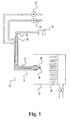
- Fig. 1 schematically illustrates a preferred embodiment of an apparatus 40 for controlled agglomeration according to the present invention.
- the illustrated apparatus 40 comprises a spray nozzle 10 according to the present invention.
- the apparatus 40 further comprises a fluid bed 42 for fluidisation of a second composition 44 at ambient temperature.
- the spray nozzle 10 is mounted above the fluid bed 42 for spraying a first composition 46 comprising the carrier 48 in liquid form on the second composition 44 fluidised in the fluid bed 42.
- a temperature and pressure controlled tank 50 of the apparatus 40 contains the first composition 46 and is connected to the central tube 26 with the central passage 12 for supply of the first composition 46 at a temperature above the melting point of the carrier 48.
- Temperature controlled primary air is supplied to the spray nozzle 10 from a first temperature controlled pressurised air supply 52 that is connected to the second tube 28.
- Temperature controlled secondary air is supplied to the spray nozzle 10 from a second temperature controlled pressurised air supply 54 that is connected to the third tube 30.
- agglomeration makes it possible to obtain a particulate material that has a very high load of carrier(s) - much higher than described when conventional methods like e.g. melt granulation is employed.
- a high load of carrier has shown to be of importance especially when particulate material is prepared containing a slightly water-soluble, sparingly water soluble or insoluble active substances.
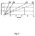
- Fig. 3 is a theoretically calculated curve showing the relationship between obtainable dose and drug solubility in a carrier composition at different carrier concentrations in the particulate material assuming a total composition weight of 500 mg. It is seen that the dose can be increased by a factor of about 3.5 by increasing the concentration of carrier from 20% to 70%.
- Another granulation method which makes use of the same temperature of the binder and the material to be granulated, is a conventional granulation process, which is performed either by a wet or a dry granulation process.
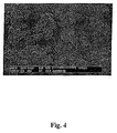
- FIG. 4 shows a particulate material prepared by an apparatus according to the present invention.
- PEG 6000 is used as a carrier and lactose is used as the second composition.
- Fig. 4 shows that the primary particles of lactose are agglomerated by immersion in the droplets of PEG 6000 or by coalescence between larger agglomerates. The agglomerates are partly coated with PEG 6000. The probability of agglomerate growth by coalescence is reduced by rapidly solidifying PEG due to the product temperature being kept at a minimum of 10 °C below the melting point of PEG.
- Fig. 5 shows that the particulate material has larger agglomerates with surplus of liquefied PEG at the surface of the agglomerates increasing the probability of agglomerate growth by coalescence at elevated product temperature.
- the particulate material obtained by an apparatus of the invention has a geometric weight mean diameter d gw of ⁇ 10 ⁇ m such as, e.g., ⁇ 20 ⁇ m, from about 20 to about 2000, from about 30 to about 2000, from about 50 to about 2000, from about 60 to about 2000, from about 75 to about 2000 such as, e.g. from about 100 to about 1500 ⁇ m, from about 100 to about 1000 ⁇ m or from about 100 to about 700 ⁇ m.
- the geometric weight mean diameter d gw is at the most about 400 ⁇ m or at the most 300 ⁇ m such as, e.g., from about 50 to about 400 ⁇ m such as, e.g., from about 50 to about 350 ⁇ m, from about 50 to about 300 ⁇ m, from about 50 to about 250 ⁇ m or from about 100 to about 300 ⁇ m.
- a particulate material has good tabletting properties including good flowability and compactability. It has no or minimal adherence to the tabletting equipment either in itself or after addition of the normal amount of lubricants. It is an excellent alternative for incorporation of active substances with very low water solubility and/or with a very low bioavailability, or active substances, which are subject to degradation in the presence of water (the process may be carried out without any water).
- a particulate material of the invention is excellent for a further processing into e.g. tablets.
- tablets are normally easier and cheaper to produce and tablets are often preferred by the patient.
- a tablet formulation is relatively easy to adjust to specific requirements, e.g. with respect to release of the active substance, size etc.
- the particulate material obtained by an apparatus according to the invention may be used as such, or it may be further processed to the manufacture of a pharmaceutical and/or a cosmetic composition by addition of one or more suitable pharmaceutically and/or cosmetically acceptable excipients. Furthermore, the particulate material obtained may be provided with a coating to obtain coated particles, granules or pellets. Suitable coatings may be employed in order to obtain composition for immediate or modified release of the active substance and the coating employed is normally selected from the group consisting of film-coatings (for immediate or modified release) and enteric coatings or other kinds of modified release coatings, protective coatings or anti-adhesive coatings
- the particulate material obtained by an apparatus of the invention is especially suitable for further processing into tablets.
- the material possesses suitable properties for tabletting purposes, cf. below, but in some cases it may be suitable to add further therapeutically and/or prophylactically active substances and/or excipients to the particulate material before the manufacture of tablets.
- a suitable release pattern can be designed in order to obtain a relatively fast release of an active substance followed by a modified (i.e. often prolonged) release of the same or a different active substance.
- a particulate material obtained by an apparatus of the invention is suitable for use in the manufacture of tablets obtained by direct compression. Furthermore, the particulate material may in itself be employed as a binding agent for use in dry granulation processes.
- a particulate material obtained by an apparatus according to the invention may be employed in any kind of pharmaceutical compositions in which the use of a solid particulate material is applicable.
- relevant pharmaceutical compositions are e.g. solid, semi-solid, fluid or liquid composition or compositions in the form of a spray.
- the particulate material may also be incorporated in a suitable drug delivery device such as, e.g. a transdermal plaster, a device for vaginal use or an implant.
- Solid compositions include powders, and compositions in dosage unit form such as, e.g. tablets, capsules, sachets, plasters, powders for injection etc.
- Semi-solid compositions include compositions like ointments, creams, lotions, suppositories, vagitories, gels, hydrogels, soaps, etc.
- Fluid or liquid compositions include solutions, dispersions such as, e.g., emulsions, suspension, mixtures, syrups, etc.
- the spray nozzle 10 comprises a central tube 26 defining a central passage 12 for supply of liquid to a nozzle tip 13.
- the central tube 26 is a flexible hose comprising a Teflon ® inner liner reinforced with a protective plastic cover.
- the hose 26 is attached to the nozzle tip 13.
- the hose 26 and the nozzle tip 13 form a unit that is removably attached to the spray nozzle 10 so that this unit may be removed and discarded and substituted by a new unit between batch processing whereby simple cleaning and sterilization of the spray nozzle is achieved.
- the nozzle tip 13 comprises a part of the central passage 12, the passage terminating in a nozzle orifice 14 for discharge of the liquid.
- the central tube 26 is surrounded by a second tube 28 whereby a first passage 16 generally surrounding and concentric with the central passage 12 for supply of primary air is defined between the central tube 26 and the second tube 28.
- the second tube 28 is terminated in a nozzle cone 32 at the end of the second tube 28 whereby a part of the first passage 16 is defined between the nozzle tip 13 and the nozzle cone 32.
- the first discharge gap 18 is formed between the nozzle cone 32 and the nozzle tip 13 at the end of the nozzle cone 32 proximate to the orifice 14.
- a thread 19 is provided for engagement with a corresponding thread provided inside the nozzle cone 32.
- the nozzle cone 32 is removably attached to the second tube 28 in threaded engagement. The size of the first discharge gap 18 may be adjusted by rotation of the nozzle cone 32.
- the second tube 28 is surrounded by a third tube 30 whereby a second passage 22 surrounding and concentric with the first passage 16 for supply of secondary air is defined between the second tube 28 and the third tube 30.
- a jacket 34 is provided at the end of the third tube 30 whereby a part of the second passage 22 is defined between the nozzle cone 32 and the jacket 34.
- a second discharge gap 24 generally concentric with the first discharge gap 18 is defined between the jacket 34 and the nozzle cone 32 at a distance upstream in relation to the first discharge gap 18.
- a thread 31 is provided for engagement with a corresponding thread in the nozzle jacket 34.
- the jacket 34 is attached to the third tube 30 in threaded engagement. The size of the second discharge gap 24 may be adjusted by rotation of the jacket.
- Temperature controlled air supplied through the second passage 22 prevents deposition of material on the outer surface of the spray nozzle 10 adjacent the orifice 14.
- the tubes 28, 30, the nozzle tip 13 and the nozzle cone 32 are made of different types stainless steel, e.g. AISI 316 and SAF 2205. It is important that parts in movable engagement with each other, e.g. the first tube 28 and the nozzle cone 32, be made of different types of stainless steel to prevent reaming.
- the jacket 34 is tapered towards the second discharge gap so that during spraying the jacket 34 substantially does not present any horizontal surfaces whereby deposition of substance on the spray nozzle is further minimised.
- surfaces of the spray nozzle may be coated, e.g. with teflon, especially in the vicinity of the orifice 14 for further inhibition of deposition of material at the spray nozzle 10 that might clog the spray nozzle and prevent further operation without cleaning.
- Fig. 7b Two embodiments of the nozzle tip 13 are illustrated in Fig. 7b with a member 15 having apertures or channels 17 for passage of the primary air.
- the channels 17 lead the primary air straight through the member 15 without changing the direction of the primary airflow.
- the longitudinal axes of the apertures or channels 17 form an angle with a longitudinal axis of the central tube whereby a swirling flow is induced in the primary airflow.
- the swirling motion of the flow creates a vortex and a region of relatively low pressure whereby the spray angle is increased.
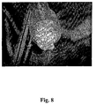
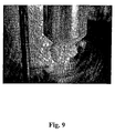
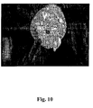
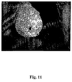
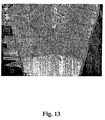
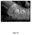
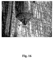
- Figs. 8-16 photographs of depositions on the spray nozzle 10 after operation in a controlled agglomeration apparatus at various operating temperatures of the primary air and the secondary air.
- FIGs. 8-12 PEG 3000 having a melting temperature in the range 48 - 54 °C was sprayed on the second composition.
- Figs. 8 and 9 show the spray nozzle after operation with an atomiser air temperature setting at 100 °C and a secondary air temperature setting at 60 °C. As seen in Figs. 8 and 9, material was deposited on the spray nozzle, and atomisation was interrupted. At these conditions, but without the first and second composition, the temperature at the spray nozzle was measured to be 48 °C, i. e. at the lower end of the melting range of PEG 3000. This is believed to cause solidification of the melted carrier at the tip of the nozzle.
- Fig. 10 shows the spray nozzle after operation with an atomiser air temperature setting at 140 °C and a secondary air temperature setting at 80 °C.
- material was deposited on the spray nozzle, however atomisation was not interrupted.
- the temperature at the spray nozzle was measured to be 59 °C, i. e. above the melting range of PEG 3000. It is believed that the nozzle surface temperature is too high causing adhesion of the melted carrier to the tip of the nozzle.
- Figs. 11 and 12 show the spray nozzle after operation with an atomiser air temperature setting at 140 °C and a secondary air temperature setting at 60 °C.
- material was deposited on the spray nozzle, however atomisation was not interrupted.
- the temperature at the spray nozzle was measured to be 58 °C, i. e. above the melting range of PEG 3000. It is believed that the nozzle surface temperature is too high causing adhesion of the melted carrier to the tip of the nozzle.
- Fig. 13 shows the spray nozzle after operation with an atomiser air temperature setting at 140 °C and a secondary air temperature setting at 100 °C.
- material was deposited on the spray nozzle, however atomisation was not interrupted.
- the temperature at the spray nozzle was measured to be 59 °C. Adhesion is probably caused by liquid droplets acting as seeds for further adhesion of solid particles.
- Fig. 14 shows the spray nozzle after operation with an atomiser air temperature setting at 140 °C and a secondary air temperature setting at 70 °C.
- material was deposited on the spray nozzle, and atomisation was very poor.
- the temperature at the spray nozzle was measured to be 52 °C, i. e. below the melting range of PEG 6000. It is believed that solidified liquid droplets and adhesion of solid particles of the second composition cause material deposition.
- Fig. 15 shows the spray nozzle after operation with an atomiser air temperature setting at 140 °C and a secondary air temperature setting at 40 °C. As seen in Fig. 15, a lot of material was deposited on the spray nozzle, and atomisation could not be achieved.
- Fig. 16 shows the spray nozzle after operation with an atomiser air temperature setting at 140 °C and a secondary air temperature setting at 80 °C. As seen in Fig. 16, very little material was deposited on the spray nozzle, and reliable atomisation was achieved. At these conditions, but without the first and second composition, the temperature at the spray nozzle was measured to be 54 °C, i. e. close to the lower limit of the melting range of PEG 6000.
- proper atomisation of the first composition requires that the atomising temperature at the nozzle orifice exceeds or at least correspond to the melting temperature of the carrier. Further, the atomisation airflow must be sufficient for atomisation of the first composition.
- the temperature of the secondary air must be sufficiently low to cool the surface of the nozzle tip to the lower end of the melting temperature range of the carrier. If the temperature is higher, adhesion of liquid droplets might result in deposits of solid second composition material. If the temperature is lower, liquid droplets might solidify and act as seeding for build up of deposits.
- the secondary airflow should be sufficient to create a heating zone around the nozzle and reduce the deposits of solid particles around the orifice in the counter current airflow of the fluid bed.
- the example illustrates the preparation of a particulate material comprising a relatively large amount of a carrier.
- the particulate material obtained exhibits good flowability, good compactability and possesses excellent tabletting properties.
- the particulate material allow the preparation of e.g. tablets and in spite of the relatively large load of carrier the tablets display minimal, if any, adherence (sticking) to tablet punches and/or dies during compression.
- the tablets obtained have acceptable properties with respect to disintegration, weight variation and hardness.
- Fluid bed Strea-1 (from Aeromatic-Fielder) mounted with a spray nozzle according to the present invention with an orifice of 0.8 mm.
- the composition has a carrier concentration of 45.6% w/w.
- the composition has a carrier concentration of 29.6% w/w.
- Lactose (or for composition 1.2 calcium hydrogen phosphate anhydrous) was fluidised at appropriate inlet airflow.
- the inlet air was not heated.
- PEG 6000 was melted using an electrically heated pressure tank. The temperature was kept at a temperature at about 85 °C, i.e. above the melting point of PEG 6000. The melt was pumped from the tank to the nozzle through a heated tube. In the tube, the temperature was kept at 80 °C. The pressure in the tank determined the flow rate of the melt.
- the nozzle was heated to keep the droplets in a liquefied stage by means of heating the atomizer air delivered through the top-spray nozzle.
- composition 1.1 and 1.2 appear as free flowing granular products with a mean granule size of approx. 300-500 ⁇ m.
- Controlled agglomeration is obtained by keeping the product temperature at minimum10 °C below melting point of the carrier reducing the probability of agglomeration due to coalescence. Controlled agglomeration is characterised by gradual increase in mean granule size (geometric weight mean diameter d gw ) as function of applied amount of carrier. In contrast, uncontrolled agglomeration shows rapidly increasing granule size. As a proof of concept the granule growth pattern are compared corresponding to the following conditions:
- Fluid bed Strea-1 mounted with a spray nozzle according to the present invention.
- Fig. 17 is a photograph of a preferred embodiment of a spray nozzle according to the present invention, operating with a low spray angle of approximately 5°.
Landscapes
- Medicinal Preparation (AREA)
- Detergent Compositions (AREA)
- Nozzles (AREA)
- Glanulating (AREA)
Applications Claiming Priority (3)
| Application Number | Priority Date | Filing Date | Title |
|---|---|---|---|
| DKPA200201987 | 2002-12-20 | ||
| DK200201987 | 2002-12-20 | ||
| PCT/DK2003/000932 WO2004056487A1 (en) | 2002-12-20 | 2003-12-22 | A self-cleaning spray nozzle |
Publications (2)
| Publication Number | Publication Date |
|---|---|
| EP1497034A1 EP1497034A1 (en) | 2005-01-19 |
| EP1497034B1 true EP1497034B1 (en) | 2006-07-12 |
Family
ID=32668629
Family Applications (1)
| Application Number | Title | Priority Date | Filing Date |
|---|---|---|---|
| EP03767489A Expired - Lifetime EP1497034B1 (en) | 2002-12-20 | 2003-12-22 | A self-cleaning spray nozzle |
Country Status (11)
| Country | Link |
|---|---|
| US (1) | US7252247B2 (enExample) |
| EP (1) | EP1497034B1 (enExample) |
| JP (1) | JP4330539B2 (enExample) |
| CN (1) | CN100415383C (enExample) |
| AT (1) | ATE332756T1 (enExample) |
| AU (1) | AU2003291973A1 (enExample) |
| CA (1) | CA2511150C (enExample) |
| DE (1) | DE60306760T2 (enExample) |
| DK (1) | DK1497034T3 (enExample) |
| ES (1) | ES2268434T3 (enExample) |
| WO (1) | WO2004056487A1 (enExample) |
Cited By (6)
| Publication number | Priority date | Publication date | Assignee | Title |
|---|---|---|---|---|
| WO2020212025A1 (de) | 2019-04-18 | 2020-10-22 | Glatt Gesellschaft Mit Beschränkter Haftung | Selbstreinigende düse |
| WO2020212026A1 (de) | 2019-04-18 | 2020-10-22 | Glatt Gesellschaft Mit Beschränkter Haftung | Selbstreinigende düse |
| WO2020212023A1 (de) * | 2019-04-18 | 2020-10-22 | Glatt Gesellschaft Mit Beschränkter Haftung | VERSCHLIEßBARE DÜSE |
| WO2020212024A1 (de) | 2019-04-18 | 2020-10-22 | Glatt Gesellschaft Mit Beschränkter Haftung | Verfahren zur steuerung des volumenstroms einer düse |
| WO2020212027A1 (de) | 2019-04-18 | 2020-10-22 | Glatt Gesellschaft Mit Beschränkter Haftung | Verfahren zur überwachung eines düsenmundstücks auf ablagerungen an einer düse |
| DE102020213179A1 (de) | 2020-10-19 | 2022-04-21 | Glatt Gesellschaft Mit Beschränkter Haftung | Düse zum Versprühen von Stoffen und Verfahren zur Steuerung oder Regelung der Düse |
Families Citing this family (36)
| Publication number | Priority date | Publication date | Assignee | Title |
|---|---|---|---|---|
| WO2005032525A1 (en) * | 2003-10-03 | 2005-04-14 | Lifecycle Pharma A/S | A method for preparing modified release pharmaceutical compositions |
| JP4171007B2 (ja) * | 2005-07-06 | 2008-10-22 | 本田技研工業株式会社 | 塗布ガンの洗浄方法 |
| DE102005048489A1 (de) * | 2005-10-07 | 2007-04-19 | Dieter Prof. Dr.-Ing. Wurz | Zweistoffdüse mit Ringspaltzerstäubung |
| JP2007160262A (ja) * | 2005-12-15 | 2007-06-28 | Fuji Paudal Co Ltd | 流動層装置 |
| CN100391652C (zh) * | 2006-10-10 | 2008-06-04 | 陈华 | 具有在线自动排污功能的喷嘴装置 |
| JP5333892B2 (ja) * | 2007-06-11 | 2013-11-06 | 株式会社リコー | 造粒・コーティング方法および装置、並びにその方法を用いた電子写真用キャリアのコーティング方法および電子写真用キャリア |
| US8408480B2 (en) * | 2008-04-25 | 2013-04-02 | Confluent Surgical, Inc. | Self-cleaning spray tip |
| US8033483B2 (en) | 2008-04-25 | 2011-10-11 | Confluent Surgical Inc. | Silicone spray tip |
| US8210453B2 (en) | 2008-09-12 | 2012-07-03 | Confluent Surgical, Inc. | Spray applicator |
| CH699808A1 (de) * | 2008-10-30 | 2010-04-30 | Medmix Systems Ag | Sprühkopf und Sprühvorrichtung mit einem solchen Sprühkopf. |
| WO2011038460A1 (en) * | 2009-10-01 | 2011-04-07 | Spray Nozzel Engineering Pty. Limited | Improved spray nozzle surfaces |
| KR101187802B1 (ko) | 2010-04-30 | 2012-10-16 | 한국과학기술원 | 에어로졸 분사 장치 |
| CN101884962B (zh) * | 2010-07-09 | 2013-05-08 | 中冶京诚工程技术有限公司 | 不堵塞、无气阻的锥面气雾喷嘴及锥面气雾形成方法 |
| JP2012035235A (ja) * | 2010-08-11 | 2012-02-23 | Chugai Ro Co Ltd | 噴霧装置および粉体製造装置 |
| JP2012223724A (ja) * | 2011-04-21 | 2012-11-15 | Ihi Corp | 塗装用スプレーガン及び塗装装置 |
| US10290381B2 (en) | 2011-12-30 | 2019-05-14 | Ge-Hitachi Nuclear Energy Americas Llc | Method and apparatus for a high-temperature deposition solution injector |
| US10309430B2 (en) | 2012-08-10 | 2019-06-04 | Confluent Surgical, Inc. | Pneumatic actuation assembly |
| US9761336B2 (en) | 2012-12-20 | 2017-09-12 | Ge-Hitachi Nuclear Energy Americas Llc | Insulated solution injector, system including the same, and method of injecting using the same |
| DE102014100605A1 (de) * | 2014-01-21 | 2015-07-23 | Paperchine Gmbh | Düsenanordnung mit selbstreinigender Frontfläche |
| WO2015153828A1 (en) | 2014-04-04 | 2015-10-08 | Hyperbranch Medical Technology, Inc. | Extended tip spray applicator for two-component surgical selant, and methods of use thereof |
| CN103964560A (zh) * | 2014-05-26 | 2014-08-06 | 英尼奥斯欧洲股份公司 | 用于酸添加的进口喷嘴 |
| CN104069976B (zh) * | 2014-06-11 | 2016-08-24 | 华南理工大学 | 一种可清除喷嘴挂胶的雾化喷嘴 |
| DE102015114202A1 (de) | 2015-07-17 | 2017-01-19 | Sms Group Gmbh | Sprühkopf zur Kühlschmierung mindestens eines Gesenks einer Umformmaschine sowie Verfahren zur Herstellung eines derartigen Sprühkopfs |
| US10515729B2 (en) * | 2015-11-04 | 2019-12-24 | Ge-Hitachi Nuclear Energy Americas Llc | Insulated solution injector including an insulating liner, system including the same, and method of injecting using the same |
| EP3439612B1 (de) * | 2016-04-05 | 2020-04-01 | Jan Franck | Vorrichtung und verfahren zur dosierung von wirkstoffen für die zubereitung von medikamenten |
| DE102017100438B4 (de) * | 2017-01-11 | 2024-12-12 | Sms Group Gmbh | Zweistoffdüse, Sprühkopf sowie Verfahren zum Zerstäuben eines Gemisches aus Sprühmittel und Sprühluft mittels einer Zweistoffdüse |
| JP2018130224A (ja) * | 2017-02-14 | 2018-08-23 | 株式会社フェザーグラス | 吸入装置 |
| CN208098453U (zh) * | 2017-10-25 | 2018-11-16 | 惠科股份有限公司 | 清洁装置和镀膜设备 |
| CN108580076A (zh) * | 2018-04-28 | 2018-09-28 | 北京航天发射技术研究所 | 一种内雾化喷嘴及使用该内雾化喷嘴的内雾化喷头 |
| DE102018111083A1 (de) * | 2018-05-08 | 2019-11-14 | Broetje-Automation Gmbh | Zerstäubereinheit eines Minimalmengenschmiersystems |
| CN108644600A (zh) * | 2018-05-18 | 2018-10-12 | 东莞安默琳机械制造技术有限公司 | 微量润滑喷嘴 |
| JP7147523B2 (ja) * | 2018-12-06 | 2022-10-05 | 三生医薬株式会社 | 造粒方法 |
| CN110369169B (zh) * | 2019-06-21 | 2021-04-20 | 汇专科技集团股份有限公司 | 雾化喷嘴及雾化装置 |
| KR102388407B1 (ko) | 2019-07-02 | 2022-04-21 | 세메스 주식회사 | 노즐 장치, 기판 처리 장치 및 방법 |
| CN110404486B (zh) * | 2019-07-05 | 2024-04-02 | 金华职业技术学院 | 一种凝胶小球的制备方法 |
| DE102021107482A1 (de) | 2021-03-25 | 2022-09-29 | Verein zur Förderung von Innovationen durch Forschung, Entwicklung und Technologietransfer e.V. (Verein INNOVENT e.V.) | Zerstäuberdüse |
Family Cites Families (16)
| Publication number | Priority date | Publication date | Assignee | Title |
|---|---|---|---|---|
| US2712961A (en) * | 1950-12-21 | 1955-07-12 | Research Corp | Spray device |
| FR1125303A (fr) | 1954-05-27 | 1956-10-29 | Brûleur à huile à alimentation sous pression, notamment pour le chauffage des fours | |
| US3746253A (en) * | 1970-09-21 | 1973-07-17 | Walberg & Co A | Coating system |
| US3929291A (en) * | 1973-05-24 | 1975-12-30 | Pfrengle Otto | Spray mixing nozzle |
| US4347984A (en) * | 1974-04-01 | 1982-09-07 | Ppg Industries, Inc. | Electrostatic spray coating apparatus |
| US4036434A (en) * | 1974-07-15 | 1977-07-19 | Aerojet-General Corporation | Fluid delivery nozzle with fluid purged face |
| DE2746489C2 (de) * | 1977-10-15 | 1982-12-30 | Hans Dr. 3300 Braunschweig Junginger | Verfahren zum Herstellen von Mikrokapseln mit Flüssigkeits- und/oder mit Feststoff-Füllungen durch Sprühtrocknung unter Verwendung einer Dreifachdüse |
| NL8303000A (nl) * | 1983-08-27 | 1985-03-18 | Unie Van Kunstmestfab Bv | Werkwijze voor het bereiden van granules. |
| US5697553A (en) * | 1995-03-03 | 1997-12-16 | Parker-Hannifin Corporation | Streaked spray nozzle for enhanced air/fuel mixing |
| CN2259230Y (zh) * | 1996-04-03 | 1997-08-13 | 吴道洪 | 两相流高效液体雾化器 |
| US5884846A (en) * | 1996-09-19 | 1999-03-23 | Tan; Hsiaoming Sherman | Pneumatic concentric nebulizer with adjustable and capillaries |
| AU2705600A (en) * | 1998-10-01 | 2000-05-01 | University Of Akron, The | Process and apparatus for the production of nanofibers |
| CN2442755Y (zh) * | 2000-09-14 | 2001-08-15 | 黄条祥 | 可替换的喷枪喷嘴头结构 |
| DE10116051B4 (de) | 2001-03-30 | 2009-01-15 | Glatt Ingenieurtechnik Gmbh | Sprühdüse für Wirbelschichtanlagen |
| GB0130131D0 (en) | 2001-12-17 | 2002-02-06 | Glaxo Group Ltd | Novel process and apparatus |
| ITMI20012693A1 (it) * | 2001-12-19 | 2003-06-19 | Zambon Spa | Unita' di spruzzo di uno spray dryer |
-
2003
- 2003-12-22 AT AT03767489T patent/ATE332756T1/de active
- 2003-12-22 WO PCT/DK2003/000932 patent/WO2004056487A1/en not_active Ceased
- 2003-12-22 ES ES03767489T patent/ES2268434T3/es not_active Expired - Lifetime
- 2003-12-22 CA CA2511150A patent/CA2511150C/en not_active Expired - Lifetime
- 2003-12-22 EP EP03767489A patent/EP1497034B1/en not_active Expired - Lifetime
- 2003-12-22 DE DE60306760T patent/DE60306760T2/de not_active Expired - Lifetime
- 2003-12-22 CN CNB2003801068798A patent/CN100415383C/zh not_active Expired - Lifetime
- 2003-12-22 US US10/519,992 patent/US7252247B2/en not_active Expired - Lifetime
- 2003-12-22 JP JP2004561101A patent/JP4330539B2/ja not_active Expired - Lifetime
- 2003-12-22 DK DK03767489T patent/DK1497034T3/da active
- 2003-12-22 AU AU2003291973A patent/AU2003291973A1/en not_active Abandoned
Cited By (10)
| Publication number | Priority date | Publication date | Assignee | Title |
|---|---|---|---|---|
| WO2020212025A1 (de) | 2019-04-18 | 2020-10-22 | Glatt Gesellschaft Mit Beschränkter Haftung | Selbstreinigende düse |
| WO2020212026A1 (de) | 2019-04-18 | 2020-10-22 | Glatt Gesellschaft Mit Beschränkter Haftung | Selbstreinigende düse |
| WO2020212023A1 (de) * | 2019-04-18 | 2020-10-22 | Glatt Gesellschaft Mit Beschränkter Haftung | VERSCHLIEßBARE DÜSE |
| WO2020212024A1 (de) | 2019-04-18 | 2020-10-22 | Glatt Gesellschaft Mit Beschränkter Haftung | Verfahren zur steuerung des volumenstroms einer düse |
| WO2020212027A1 (de) | 2019-04-18 | 2020-10-22 | Glatt Gesellschaft Mit Beschränkter Haftung | Verfahren zur überwachung eines düsenmundstücks auf ablagerungen an einer düse |
| US11878315B2 (en) | 2019-04-18 | 2024-01-23 | Glatt Gesellschaft Mit Beschränkter Haftung | Closeable nozzle |
| US11931757B2 (en) | 2019-04-18 | 2024-03-19 | Glatt Gesellschaft Mit Beschränkter Haftung | Method for monitoring a nozzle mouthpiece for placing on a nozzle |
| US12295915B2 (en) | 2019-04-18 | 2025-05-13 | Glatt Gesellschaft Mit Beschränkter Haftung | Method for controlling the volume flow rate from a nozzle |
| DE102020213179A1 (de) | 2020-10-19 | 2022-04-21 | Glatt Gesellschaft Mit Beschränkter Haftung | Düse zum Versprühen von Stoffen und Verfahren zur Steuerung oder Regelung der Düse |
| WO2022084034A1 (de) | 2020-10-19 | 2022-04-28 | Glatt Gesellschaft Mit Beschränkter Haftung | Düse zum versprühen von stoffen und verfahren zur steuerung oder regelung der düse |
Also Published As
| Publication number | Publication date |
|---|---|
| DK1497034T3 (da) | 2006-11-13 |
| CA2511150C (en) | 2010-07-06 |
| AU2003291973A1 (en) | 2004-07-14 |
| JP4330539B2 (ja) | 2009-09-16 |
| EP1497034A1 (en) | 2005-01-19 |
| JP2006510476A (ja) | 2006-03-30 |
| ATE332756T1 (de) | 2006-08-15 |
| DE60306760T2 (de) | 2007-08-16 |
| US20050242209A1 (en) | 2005-11-03 |
| CA2511150A1 (en) | 2004-07-08 |
| DE60306760D1 (de) | 2006-08-24 |
| CN1729059A (zh) | 2006-02-01 |
| CN100415383C (zh) | 2008-09-03 |
| WO2004056487A1 (en) | 2004-07-08 |
| ES2268434T3 (es) | 2007-03-16 |
| US7252247B2 (en) | 2007-08-07 |
Similar Documents
| Publication | Publication Date | Title |
|---|---|---|
| EP1497034B1 (en) | A self-cleaning spray nozzle | |
| US7217431B2 (en) | Controlled agglomeration | |
| AU2002325192A1 (en) | Controlled agglomeration | |
| CA2572180C (en) | Porous tablets as carriers for liquid formulations | |
| US20070122482A1 (en) | Method for preparing modified release pharmaceutical compositions | |
| CA2634160A1 (en) | Disintegrating loadable tablets | |
| WO2004062643A1 (en) | Dry dispersions | |
| WO2004073689A1 (en) | Use of a silica or silica derivative as a sorption material | |
| CN1758901B (zh) | 硅石或硅石衍生物作为吸附材料的用途 | |
| HK1147945A (en) | Controlled agglomeration |
Legal Events
| Date | Code | Title | Description |
|---|---|---|---|
| PUAI | Public reference made under article 153(3) epc to a published international application that has entered the european phase |
Free format text: ORIGINAL CODE: 0009012 |
|
| 17P | Request for examination filed |
Effective date: 20041112 |
|
| AK | Designated contracting states |
Kind code of ref document: A1 Designated state(s): AT BE BG CH CY CZ DE DK EE ES FI FR GB GR HU IE IT LI LU MC NL PT RO SE SI SK TR |
|
| AX | Request for extension of the european patent |
Extension state: AL LT LV MK |
|
| 17Q | First examination report despatched |
Effective date: 20050404 |
|
| GRAP | Despatch of communication of intention to grant a patent |
Free format text: ORIGINAL CODE: EPIDOSNIGR1 |
|
| DAX | Request for extension of the european patent (deleted) | ||
| GRAS | Grant fee paid |
Free format text: ORIGINAL CODE: EPIDOSNIGR3 |
|
| GRAA | (expected) grant |
Free format text: ORIGINAL CODE: 0009210 |
|
| AK | Designated contracting states |
Kind code of ref document: B1 Designated state(s): AT BE BG CH CY CZ DE DK EE ES FI FR GB GR HU IE IT LI LU MC NL PT RO SE SI SK TR |
|
| PG25 | Lapsed in a contracting state [announced via postgrant information from national office to epo] |
Ref country code: IT Free format text: LAPSE BECAUSE OF FAILURE TO SUBMIT A TRANSLATION OF THE DESCRIPTION OR TO PAY THE FEE WITHIN THE PRESCRIBED TIME-LIMIT;WARNING: LAPSES OF ITALIAN PATENTS WITH EFFECTIVE DATE BEFORE 2007 MAY HAVE OCCURRED AT ANY TIME BEFORE 2007. THE CORRECT EFFECTIVE DATE MAY BE DIFFERENT FROM THE ONE RECORDED. Effective date: 20060712 Ref country code: SI Free format text: LAPSE BECAUSE OF FAILURE TO SUBMIT A TRANSLATION OF THE DESCRIPTION OR TO PAY THE FEE WITHIN THE PRESCRIBED TIME-LIMIT Effective date: 20060712 Ref country code: FI Free format text: LAPSE BECAUSE OF FAILURE TO SUBMIT A TRANSLATION OF THE DESCRIPTION OR TO PAY THE FEE WITHIN THE PRESCRIBED TIME-LIMIT Effective date: 20060712 Ref country code: CZ Free format text: LAPSE BECAUSE OF FAILURE TO SUBMIT A TRANSLATION OF THE DESCRIPTION OR TO PAY THE FEE WITHIN THE PRESCRIBED TIME-LIMIT Effective date: 20060712 Ref country code: RO Free format text: LAPSE BECAUSE OF FAILURE TO SUBMIT A TRANSLATION OF THE DESCRIPTION OR TO PAY THE FEE WITHIN THE PRESCRIBED TIME-LIMIT Effective date: 20060712 Ref country code: SK Free format text: LAPSE BECAUSE OF FAILURE TO SUBMIT A TRANSLATION OF THE DESCRIPTION OR TO PAY THE FEE WITHIN THE PRESCRIBED TIME-LIMIT Effective date: 20060712 |
|
| REG | Reference to a national code |
Ref country code: GB Ref legal event code: FG4D |
|
| REG | Reference to a national code |
Ref country code: CH Ref legal event code: EP |
|
| REG | Reference to a national code |
Ref country code: IE Ref legal event code: FG4D |
|
| REF | Corresponds to: |
Ref document number: 60306760 Country of ref document: DE Date of ref document: 20060824 Kind code of ref document: P |
|
| PG25 | Lapsed in a contracting state [announced via postgrant information from national office to epo] |
Ref country code: BG Free format text: LAPSE BECAUSE OF FAILURE TO SUBMIT A TRANSLATION OF THE DESCRIPTION OR TO PAY THE FEE WITHIN THE PRESCRIBED TIME-LIMIT Effective date: 20061012 Ref country code: SE Free format text: LAPSE BECAUSE OF FAILURE TO SUBMIT A TRANSLATION OF THE DESCRIPTION OR TO PAY THE FEE WITHIN THE PRESCRIBED TIME-LIMIT Effective date: 20061012 |
|
| REG | Reference to a national code |
Ref country code: CH Ref legal event code: NV Representative=s name: PETER RUTZ |
|
| REG | Reference to a national code |
Ref country code: DK Ref legal event code: T3 |
|
| PG25 | Lapsed in a contracting state [announced via postgrant information from national office to epo] |
Ref country code: PT Free format text: LAPSE BECAUSE OF FAILURE TO SUBMIT A TRANSLATION OF THE DESCRIPTION OR TO PAY THE FEE WITHIN THE PRESCRIBED TIME-LIMIT Effective date: 20061212 |
|
| PG25 | Lapsed in a contracting state [announced via postgrant information from national office to epo] |
Ref country code: MC Free format text: LAPSE BECAUSE OF NON-PAYMENT OF DUE FEES Effective date: 20061231 |
|
| ET | Fr: translation filed | ||
| REG | Reference to a national code |
Ref country code: ES Ref legal event code: FG2A Ref document number: 2268434 Country of ref document: ES Kind code of ref document: T3 |
|
| PLBE | No opposition filed within time limit |
Free format text: ORIGINAL CODE: 0009261 |
|
| STAA | Information on the status of an ep patent application or granted ep patent |
Free format text: STATUS: NO OPPOSITION FILED WITHIN TIME LIMIT |
|
| 26N | No opposition filed |
Effective date: 20070413 |
|
| PG25 | Lapsed in a contracting state [announced via postgrant information from national office to epo] |
Ref country code: GR Free format text: LAPSE BECAUSE OF FAILURE TO SUBMIT A TRANSLATION OF THE DESCRIPTION OR TO PAY THE FEE WITHIN THE PRESCRIBED TIME-LIMIT Effective date: 20061013 |
|
| PG25 | Lapsed in a contracting state [announced via postgrant information from national office to epo] |
Ref country code: EE Free format text: LAPSE BECAUSE OF FAILURE TO SUBMIT A TRANSLATION OF THE DESCRIPTION OR TO PAY THE FEE WITHIN THE PRESCRIBED TIME-LIMIT Effective date: 20060712 |
|
| PG25 | Lapsed in a contracting state [announced via postgrant information from national office to epo] |
Ref country code: HU Free format text: LAPSE BECAUSE OF FAILURE TO SUBMIT A TRANSLATION OF THE DESCRIPTION OR TO PAY THE FEE WITHIN THE PRESCRIBED TIME-LIMIT Effective date: 20070113 Ref country code: TR Free format text: LAPSE BECAUSE OF FAILURE TO SUBMIT A TRANSLATION OF THE DESCRIPTION OR TO PAY THE FEE WITHIN THE PRESCRIBED TIME-LIMIT Effective date: 20060712 |
|
| PG25 | Lapsed in a contracting state [announced via postgrant information from national office to epo] |
Ref country code: CY Free format text: LAPSE BECAUSE OF FAILURE TO SUBMIT A TRANSLATION OF THE DESCRIPTION OR TO PAY THE FEE WITHIN THE PRESCRIBED TIME-LIMIT Effective date: 20060712 |
|
| REG | Reference to a national code |
Ref country code: FR Ref legal event code: PLFP Year of fee payment: 13 |
|
| REG | Reference to a national code |
Ref country code: FR Ref legal event code: PLFP Year of fee payment: 14 |
|
| REG | Reference to a national code |
Ref country code: FR Ref legal event code: PLFP Year of fee payment: 15 |
|
| REG | Reference to a national code |
Ref country code: CH Ref legal event code: PCAR Free format text: NEW ADDRESS: ALPENSTRASSE 14 POSTFACH 7627, 6302 ZUG (CH) |
|
| PGFP | Annual fee paid to national office [announced via postgrant information from national office to epo] |
Ref country code: NL Payment date: 20221114 Year of fee payment: 20 Ref country code: LU Payment date: 20221216 Year of fee payment: 20 Ref country code: IE Payment date: 20221011 Year of fee payment: 20 Ref country code: GB Payment date: 20221103 Year of fee payment: 20 Ref country code: FR Payment date: 20221110 Year of fee payment: 20 Ref country code: DK Payment date: 20221213 Year of fee payment: 20 Ref country code: DE Payment date: 20221025 Year of fee payment: 20 Ref country code: AT Payment date: 20221125 Year of fee payment: 20 |
|
| PGFP | Annual fee paid to national office [announced via postgrant information from national office to epo] |
Ref country code: BE Payment date: 20221118 Year of fee payment: 20 |
|
| PGFP | Annual fee paid to national office [announced via postgrant information from national office to epo] |
Ref country code: ES Payment date: 20230110 Year of fee payment: 20 Ref country code: CH Payment date: 20230101 Year of fee payment: 20 |
|
| REG | Reference to a national code |
Ref country code: DE Ref legal event code: R071 Ref document number: 60306760 Country of ref document: DE |
|
| REG | Reference to a national code |
Ref country code: NL Ref legal event code: MK Effective date: 20231221 |
|
| REG | Reference to a national code |
Ref country code: CH Ref legal event code: PL |
|
| REG | Reference to a national code |
Ref country code: ES Ref legal event code: FD2A Effective date: 20240102 Ref country code: DK Ref legal event code: EUP Expiry date: 20231222 |
|
| REG | Reference to a national code |
Ref country code: GB Ref legal event code: PE20 Expiry date: 20231221 |
|
| PG25 | Lapsed in a contracting state [announced via postgrant information from national office to epo] |
Ref country code: GB Free format text: LAPSE BECAUSE OF EXPIRATION OF PROTECTION Effective date: 20231221 |
|
| REG | Reference to a national code |
Ref country code: BE Ref legal event code: MK Effective date: 20231222 |
|
| PG25 | Lapsed in a contracting state [announced via postgrant information from national office to epo] |
Ref country code: ES Free format text: LAPSE BECAUSE OF EXPIRATION OF PROTECTION Effective date: 20231223 |
|
| PG25 | Lapsed in a contracting state [announced via postgrant information from national office to epo] |
Ref country code: GB Free format text: LAPSE BECAUSE OF EXPIRATION OF PROTECTION Effective date: 20231221 Ref country code: ES Free format text: LAPSE BECAUSE OF EXPIRATION OF PROTECTION Effective date: 20231223 |
|
| REG | Reference to a national code |
Ref country code: IE Ref legal event code: MK9A |
|
| REG | Reference to a national code |
Ref country code: AT Ref legal event code: MK07 Ref document number: 332756 Country of ref document: AT Kind code of ref document: T Effective date: 20231222 |
|
| PG25 | Lapsed in a contracting state [announced via postgrant information from national office to epo] |
Ref country code: IE Free format text: LAPSE BECAUSE OF EXPIRATION OF PROTECTION Effective date: 20231222 |
|
| PG25 | Lapsed in a contracting state [announced via postgrant information from national office to epo] |
Ref country code: IE Free format text: LAPSE BECAUSE OF EXPIRATION OF PROTECTION Effective date: 20231222 |