EP1496239A2 - Sammelbehälter für ein Kraftstoffdampfsystem - Google Patents
Sammelbehälter für ein Kraftstoffdampfsystem Download PDFInfo
- Publication number
- EP1496239A2 EP1496239A2 EP04460022A EP04460022A EP1496239A2 EP 1496239 A2 EP1496239 A2 EP 1496239A2 EP 04460022 A EP04460022 A EP 04460022A EP 04460022 A EP04460022 A EP 04460022A EP 1496239 A2 EP1496239 A2 EP 1496239A2
- Authority
- EP
- European Patent Office
- Prior art keywords
- valve
- canister
- adsorbing
- vapour
- perforated plate
- Prior art date
- Legal status (The legal status is an assumption and is not a legal conclusion. Google has not performed a legal analysis and makes no representation as to the accuracy of the status listed.)
- Withdrawn
Links
- 239000000446 fuel Substances 0.000 title claims abstract description 46
- 239000003463 adsorbent Substances 0.000 claims abstract description 14
- 239000002828 fuel tank Substances 0.000 claims abstract description 14
- 238000002485 combustion reaction Methods 0.000 claims abstract description 9
- 230000009471 action Effects 0.000 claims abstract description 5
- 238000003780 insertion Methods 0.000 claims abstract description 4
- 230000037431 insertion Effects 0.000 claims abstract description 4
- 238000005192 partition Methods 0.000 claims description 25
- OKTJSMMVPCPJKN-UHFFFAOYSA-N Carbon Chemical compound [C] OKTJSMMVPCPJKN-UHFFFAOYSA-N 0.000 description 11
- 238000001179 sorption measurement Methods 0.000 description 8
- 238000001914 filtration Methods 0.000 description 5
- 230000002349 favourable effect Effects 0.000 description 4
- OKTJSMMVPCPJKN-BJUDXGSMSA-N carbon-11 Chemical class [11C] OKTJSMMVPCPJKN-BJUDXGSMSA-N 0.000 description 3
- 230000007423 decrease Effects 0.000 description 3
- 229930195733 hydrocarbon Natural products 0.000 description 3
- 150000002430 hydrocarbons Chemical class 0.000 description 3
- 230000000274 adsorptive effect Effects 0.000 description 2
- 239000003245 coal Substances 0.000 description 2
- 230000006835 compression Effects 0.000 description 2
- 238000007906 compression Methods 0.000 description 2
- 238000010276 construction Methods 0.000 description 2
- 239000000945 filler Substances 0.000 description 2
- 239000000463 material Substances 0.000 description 2
- 238000006386 neutralization reaction Methods 0.000 description 2
- 238000000638 solvent extraction Methods 0.000 description 2
- 241000405070 Percophidae Species 0.000 description 1
- 230000033228 biological regulation Effects 0.000 description 1
- 239000003795 chemical substances by application Substances 0.000 description 1
- 238000010586 diagram Methods 0.000 description 1
- 238000007599 discharging Methods 0.000 description 1
- 238000002474 experimental method Methods 0.000 description 1
- 238000000034 method Methods 0.000 description 1
- 230000035515 penetration Effects 0.000 description 1
- 230000008569 process Effects 0.000 description 1
- 238000011084 recovery Methods 0.000 description 1
- 230000009467 reduction Effects 0.000 description 1
- 230000004044 response Effects 0.000 description 1
- 230000006641 stabilisation Effects 0.000 description 1
- 238000011105 stabilization Methods 0.000 description 1
Images



Classifications
-
- B—PERFORMING OPERATIONS; TRANSPORTING
- B01—PHYSICAL OR CHEMICAL PROCESSES OR APPARATUS IN GENERAL
- B01D—SEPARATION
- B01D53/00—Separation of gases or vapours; Recovering vapours of volatile solvents from gases; Chemical or biological purification of waste gases, e.g. engine exhaust gases, smoke, fumes, flue gases, aerosols
- B01D53/02—Separation of gases or vapours; Recovering vapours of volatile solvents from gases; Chemical or biological purification of waste gases, e.g. engine exhaust gases, smoke, fumes, flue gases, aerosols by adsorption, e.g. preparative gas chromatography
- B01D53/04—Separation of gases or vapours; Recovering vapours of volatile solvents from gases; Chemical or biological purification of waste gases, e.g. engine exhaust gases, smoke, fumes, flue gases, aerosols by adsorption, e.g. preparative gas chromatography with stationary adsorbents
- B01D53/0407—Constructional details of adsorbing systems
- B01D53/0415—Beds in cartridges
-
- B—PERFORMING OPERATIONS; TRANSPORTING
- B01—PHYSICAL OR CHEMICAL PROCESSES OR APPARATUS IN GENERAL
- B01D—SEPARATION
- B01D53/00—Separation of gases or vapours; Recovering vapours of volatile solvents from gases; Chemical or biological purification of waste gases, e.g. engine exhaust gases, smoke, fumes, flue gases, aerosols
- B01D53/02—Separation of gases or vapours; Recovering vapours of volatile solvents from gases; Chemical or biological purification of waste gases, e.g. engine exhaust gases, smoke, fumes, flue gases, aerosols by adsorption, e.g. preparative gas chromatography
- B01D53/04—Separation of gases or vapours; Recovering vapours of volatile solvents from gases; Chemical or biological purification of waste gases, e.g. engine exhaust gases, smoke, fumes, flue gases, aerosols by adsorption, e.g. preparative gas chromatography with stationary adsorbents
- B01D53/0407—Constructional details of adsorbing systems
- B01D53/0446—Means for feeding or distributing gases
-
- F—MECHANICAL ENGINEERING; LIGHTING; HEATING; WEAPONS; BLASTING
- F02—COMBUSTION ENGINES; HOT-GAS OR COMBUSTION-PRODUCT ENGINE PLANTS
- F02M—SUPPLYING COMBUSTION ENGINES IN GENERAL WITH COMBUSTIBLE MIXTURES OR CONSTITUENTS THEREOF
- F02M25/00—Engine-pertinent apparatus for adding non-fuel substances or small quantities of secondary fuel to combustion-air, main fuel or fuel-air mixture
- F02M25/08—Engine-pertinent apparatus for adding non-fuel substances or small quantities of secondary fuel to combustion-air, main fuel or fuel-air mixture adding fuel vapours drawn from engine fuel reservoir
- F02M25/0854—Details of the absorption canister
-
- B—PERFORMING OPERATIONS; TRANSPORTING
- B01—PHYSICAL OR CHEMICAL PROCESSES OR APPARATUS IN GENERAL
- B01D—SEPARATION
- B01D2253/00—Adsorbents used in seperation treatment of gases and vapours
- B01D2253/10—Inorganic adsorbents
- B01D2253/102—Carbon
-
- B—PERFORMING OPERATIONS; TRANSPORTING
- B01—PHYSICAL OR CHEMICAL PROCESSES OR APPARATUS IN GENERAL
- B01D—SEPARATION
- B01D2257/00—Components to be removed
- B01D2257/70—Organic compounds not provided for in groups B01D2257/00 - B01D2257/602
- B01D2257/702—Hydrocarbons
-
- B—PERFORMING OPERATIONS; TRANSPORTING
- B01—PHYSICAL OR CHEMICAL PROCESSES OR APPARATUS IN GENERAL
- B01D—SEPARATION
- B01D2258/00—Sources of waste gases
- B01D2258/01—Engine exhaust gases
-
- B—PERFORMING OPERATIONS; TRANSPORTING
- B01—PHYSICAL OR CHEMICAL PROCESSES OR APPARATUS IN GENERAL
- B01D—SEPARATION
- B01D2259/00—Type of treatment
- B01D2259/40—Further details for adsorption processes and devices
- B01D2259/40007—Controlling pressure or temperature swing adsorption
- B01D2259/40009—Controlling pressure or temperature swing adsorption using sensors or gas analysers
-
- B—PERFORMING OPERATIONS; TRANSPORTING
- B01—PHYSICAL OR CHEMICAL PROCESSES OR APPARATUS IN GENERAL
- B01D—SEPARATION
- B01D2259/00—Type of treatment
- B01D2259/45—Gas separation or purification devices adapted for specific applications
- B01D2259/4516—Gas separation or purification devices adapted for specific applications for fuel vapour recovery systems
-
- B—PERFORMING OPERATIONS; TRANSPORTING
- B01—PHYSICAL OR CHEMICAL PROCESSES OR APPARATUS IN GENERAL
- B01D—SEPARATION
- B01D2259/00—Type of treatment
- B01D2259/45—Gas separation or purification devices adapted for specific applications
- B01D2259/4566—Gas separation or purification devices adapted for specific applications for use in transportation means
Definitions
- the invention relates to a canister of an evaporated fuel processing system of an internal combustion engine, that enables both controlled discharge of evaporated fuel into the atmosphere, as well as neutralization of light hydrocarbons contained in evaporated fuel.
- a conventional canister of an evaporated fuel processing system is disclosed e.g. in the patent US 2002/0078931.
- the canister houses a plurality of serially connected adsorbing chambers.
- the first adsorbing chamber is connected to a fuel tank and to an intake pipe of an internal combustion engine and the last one, outlet adsorbing chamber comprises an atmospheric port.
- the fuel vapours after entering into the canister from the fuel tank, are captured by the adsorbent included in the chambers.
- activated carbon is used as the chamber-filling agent.
- the vapours After the start of the engine the vapours are inducted by negative pressure of the intake pipe and then burnt inside the combustion chamber. Once adsorptive capability of the first chamber is exhausted, the vapours pass through to successive adsorbing chambers, and after exceeding adsorptive capabilities of the outlet chamber they are discharged into the atmosphere.
- the emission of evaporated fuel into the atmosphere must be as low as possible.
- the height of adsorbing chambers should be relatively large, as compared with diameters thereof.
- the outlet adsorbing chambers is frequently divided by a partition, thus defining the outer and the inner adsorbing layer. Such a partition produces an additional restraint against vapour flow causing redistribution thereof within the entire volume of the adsorbent below the partition.
- the canisters of the above construction may fail meeting the second requirement that is demanded, which is adsorption of fuel vapour that arises while tank refuelling ( onboard refueling vapor recovery - ORVR), where the low resistance to vapour flow is required due to much higher rates of evaporated fuel flow.
- the activated carbon in the adsorbing outlet chamber generates high flow resistance, which may lead to unfavourable behaviour of the canister during tank refuelling.
- resistance of the canister may even make the refuelling impossible, as the fuel vapour sensor, installed in a pump gun, cuts the fuel flow out. Resistance to fuel vapour flow is even higher for canisters with a partition installed inside the adsorbing outlet chamber.
- the aim of the presented invention is to provide a canister of an evaporated fuel processing system, which would be free of aforementioned disadvantages, and would make it possible to obtain different operational characteristics of the canister adsorption, depending on the intensity of the fuel vapour flow and hence to meet the related emission standards.
- a canister of an evaporated fuel processing system having a housing, inside of which a number of serially connected adsorbing chambers is placed, where the first adsorbing chamber is connected to a fuel tank and to an intake pipe of an internal combustion engine and the last, outlet adsorbing chamber comprises an atmospheric port, where inside the outlet adsorbing chamber across a vapours flow path at least one perforated plate is placed.
- the canister is characterised in that, the perforated plate comprises at least one vapour channel with a valve, inserted inside the outlet adsorbing chamber for a distance less or equal to the thickness of adsorbent layer behind the perforated plate, wherein the valve remains closed when no flow of evaporated fuel through the perforated plate occurs.
- the perforated plate has form of partition with holes; such a partition divides the adsorption outlet chamber to the inner and the outer adsorbing layer.
- valve in the vapour channel is a pressure-controlled direct action valve that opens when the flow restrictions along the adsorbent layer at the lowest distance of the vapour channel insertion exceeds the valve opening pressure.
- valve in the vapour channel is a poppet valve, a duckbill valve, a flapper vale or an umbrella valve.
- valve in the vapour channel is a solenoid valve, actuated by an external signal.
- the external signal that enables opening the valve is advantageously produced by a sensor disposed in a fuel tank.
- the canister according to the present invention is distinguished by particularly good operational characteristic. If flow of evaporated fuel through the canister is low, the entire amount of the adsorbing agent is involved in adsorption process, whereas at high fuel vapour flow, e.g. during tank refuelling (ORVR), the valve opens and stabilization of pressure is reached. The evaporated fuel passes through the vapour channel and the thinner layer of the adsorbent over the vapour channel until the flow rate decreases, which results in valve closing.
- ORVR tank refuelling
- the canister according to the present invention enables meeting both the requirements of emission standards, as well as the ORVR regulations, which was extremely difficult for known constructions of canisters.
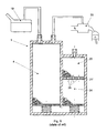
- the canister 1 of an evaporated fuel processing system comprises a housing 2, divided by the wall 3 into two adsorbing chambers 4 and 5 filled with activated carbon.
- the activated carbon 11 a is hold between filtering covers 7 and 8 being permeable for evaporated fuel.
- the squeezing strength is exerted by the perforated plate 9 and the compression spring 10.
- the activated carbon 11 b and 11c in the adsorbing outlet chamber 5 is held between filtering layers 12 and 13 being permeable for evaporated fuel by means of the perforated plate 14 and the compression spring 15.
- Filtering covers 8 and 13 protect orifices in perforated plates 9 and 14 from clogging by activated carbon, as well as prevent penetration of activated coal into the channel 6 below the plates.
- the first adsorption channel 4 is connected with the fuel tank 19 by means of the inlet port 16 and with the intake pipe 20 of an internal combustion engine by means of the outlet port 17.
- the adsorption outlet chamber 5 is discharged to the surrounding atmosphere through the atmospheric port 18.
- the first adsorbing chamber 4 is connected in series with the adsorbing outlet chamber 5 by means of the channel 6 that runs under the wall 3.
- the filtering covers 7 and 12 protect corresponding orifices 16, 17 and 18 from clogging.
- Evaporated fuel which is released from the fuel tank 19, enters the canister 1 through the inlet port 16 and diffuse in the first adsorbing chamber 4 where neutralization of light hydrocarbons is carried out.
- the fuel vapours, collected in the canister are inducted by negative pressure of the intake pipe 20 and then burnt inside the combustion chamber.
- the canister shown in Fig. 1 comprises a partition 21 with holes 28, dividing the adsorbing outlet chamber 5, hence two layers of the adsorbent are defined: the inner layer 24 and the outer layer 25 of thickness H. Filtering covers 22 and 23 protect the holes 28 in the partition 21 from clogging by the activated carbon (cf. drawing Fig. 9).
- the partition 21 serves also as additional restrain for a vapour flow into the outer layer 25 of the adsorbing outlet chamber 5 and brings about redistribution thereof within the entire volume of the activated carbon 11 a and 11 b. As a result, the entire activated coal inside the canister 1 is involved in adsorption of hydrocarbons from fuel vapour.
- the vapour channel 26 inserted inside a depth h into the outer layer 25 is formed in the partition 21.
- the vapour channel 26 comprises a pressure-controlled direct action valve. According to the present embodiment of the invention it has a form of the poppet valve 27a (shown in Fig. 3), which has a closing component 29a mounted on the stem 30a.
- the valve 27a remains closed due to action of the spring 31, which leans against appropriate projections inside the vapour channel 26.
- the valve 27a opens when flow rate reaches a predetermined value, when restrictions of the adsorbent layer along the distance h leads to pressure growth below the partition that exceeds the opening pressure of the valve.
- the vapour channel 26 with the valve is inserted into the outer layer 25 to a certain depth h, the vapour bypasses a part of adsorbent over the partition 21, thus the flow resistance is lower.
- the opening pressure of the valve 27a is adjusted proportionally to the depth h of the vapour channel 26 insertion.
- valve remains open at high flow rates; decrease of the flow rate results in reducing of flow resistance and finally in valve closing.
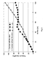
- the Fig. 2 shows the measured, experimental relationship of pressure drop (flow resistance) vs. flow rate of the air stream flowing through the canister according to the present invention (curve 1, drawing Fig. 1) compared to a conventional canister with a partition (curve 2, drawing Fig. 9).
- pressure drop is substantially proportional to the flow rate of the evaporated fuel and at defined flow rate, for a conventional canister, refuelling the vehicle can be even impossible.
- the critical value of flow resistance depends on a number of factors, which include, among others, a capacity of a fuel tank and a shape of a filler neck.
- FIG. 4 to Fig. 6 present other embodiments of the valve, mounted in the partition 21.
- the valve 27b in the drawing Fig. 4 is a flapper valve.
- the elastic closing element 29b made of plastic material is mounted on a tongue 30b attached to an orifice in the vapour channel wall 26.
- the valve 27c in the drawing Fig. 5 is a rather simple valve of duckbill type.
- the valve is made of plastic material and mounted to an orifice in the partition 21.
- Fig. 6 shows the valve 27d, which is of umbrella type.
- the closing element 29d of the valve along with its stem 30d is mounted in an appropriate orifice in the partition 21.
- the drawing Fig. 7 presents another embodiment of a canister according to the present invention.
- the adsorbing outlet chamber 5 has no partition and the vapour channel is defined in the perforated plate 14 over the spring 15.
- valve in the vapour channel is a solenoid valve 27e, connected to the control circuit 32, which actuates the valve and opens it depending on pressure of an evaporated fuel inside the fuel tank 19.
- the pressure value is measured by means of a gauge or sensor 33.
- the drawing Fig. 9 illustrates one more embodiment of a canister, which includes the partition 21 with two vapour channels 26a and 26b of depths h and h1 respectively.
- the presented embodiment comprises two flapper valves, one per each channel, with different values of opening pressure, wherein opening pressure of the valve in the shortest vapour channel 26a is the lowest. Thanks to that, the valve in the vapour channel 26a opens first and the valve in the vapour channel 26b operates as a safety valve, i.e. it opens only in case if reduction of flow resistance, caused by opening the valve in the vapour channel 26a, proves to be insufficient.
Landscapes
- Chemical & Material Sciences (AREA)
- Engineering & Computer Science (AREA)
- Analytical Chemistry (AREA)
- General Chemical & Material Sciences (AREA)
- Oil, Petroleum & Natural Gas (AREA)
- Chemical Kinetics & Catalysis (AREA)
- Combustion & Propulsion (AREA)
- Mechanical Engineering (AREA)
- General Engineering & Computer Science (AREA)
- Supplying Secondary Fuel Or The Like To Fuel, Air Or Fuel-Air Mixtures (AREA)
Applications Claiming Priority (2)
| Application Number | Priority Date | Filing Date | Title |
|---|---|---|---|
| PL03361212A PL361212A1 (en) | 2003-07-11 | 2003-07-11 | Absorber in the fuel vapour evacuation system |
| PL36121203 | 2003-07-11 |
Publications (2)
| Publication Number | Publication Date |
|---|---|
| EP1496239A2 true EP1496239A2 (de) | 2005-01-12 |
| EP1496239A3 EP1496239A3 (de) | 2007-10-31 |
Family
ID=33448595
Family Applications (1)
| Application Number | Title | Priority Date | Filing Date |
|---|---|---|---|
| EP04460022A Withdrawn EP1496239A3 (de) | 2003-07-11 | 2004-06-03 | Sammelbehälter für ein Kraftstoffdampfsystem |
Country Status (3)
| Country | Link |
|---|---|
| US (1) | US6874483B2 (de) |
| EP (1) | EP1496239A3 (de) |
| PL (1) | PL361212A1 (de) |
Cited By (2)
| Publication number | Priority date | Publication date | Assignee | Title |
|---|---|---|---|---|
| EP1788230A1 (de) | 2005-11-19 | 2007-05-23 | Delphi Technologies, Inc. | Sammelbehälter für ein Kraftstoffdampfbehandlungssystem mit einem monolithisch hergestellten Block aus Aktivkohle und Verfahren zur Herstellung derselben |
| CN103573479A (zh) * | 2012-08-08 | 2014-02-12 | 株式会社马勒滤清系统 | 罐 |
Families Citing this family (19)
| Publication number | Priority date | Publication date | Assignee | Title |
|---|---|---|---|---|
| DE102004054114A1 (de) * | 2003-12-30 | 2005-08-04 | Hyundai Motor Co. | Speicher eines Fahrzeuges |
| JP2007002709A (ja) * | 2005-06-23 | 2007-01-11 | Mahle Filter Systems Japan Corp | 活性炭及びそれを用いた蒸発燃料処理装置 |
| US7566358B2 (en) * | 2005-10-05 | 2009-07-28 | Veeder-Root Company | Fuel storage tank pressure management system and method employing a carbon canister |
| JP4718311B2 (ja) * | 2005-11-30 | 2011-07-06 | 株式会社マーレ フィルターシステムズ | キャニスタ |
| JP4522967B2 (ja) * | 2006-03-31 | 2010-08-11 | 愛三工業株式会社 | キャニスタ |
| US7900607B2 (en) * | 2007-12-20 | 2011-03-08 | Kautex Textron Gmbh & Co. Kg | Fuel vapor storage and recovery apparatus |
| JP5227214B2 (ja) * | 2009-02-19 | 2013-07-03 | 株式会社クボタ | 作業車 |
| DE102009048134B4 (de) * | 2009-10-02 | 2016-03-24 | Audi Ag | Filtereinrichtung, Kraftfahrzeug und Verfahren zum Betreiben einer Filtereinrichtung |
| US8257473B2 (en) * | 2010-07-08 | 2012-09-04 | Airsep Corporation | Sieve bed |
| KR101251052B1 (ko) * | 2010-12-06 | 2013-04-05 | 현대자동차주식회사 | 이중 공기 유동경로를 가진 캐니스터 |
| JP6017167B2 (ja) * | 2012-04-06 | 2016-10-26 | 愛三工業株式会社 | トラップキャニスタ |
| US9518538B2 (en) * | 2012-10-05 | 2016-12-13 | Ford Global Technologies, Llc | Variable restriction fuel vapor canister |
| US9359977B2 (en) * | 2013-02-20 | 2016-06-07 | Stant Usa Corp. | Fuel vapor recovery canister |
| WO2015111704A1 (ja) * | 2014-01-23 | 2015-07-30 | フタバ産業株式会社 | グリッド、及び、このグリッドを用いたキャニスタ |
| US9790898B2 (en) | 2015-04-30 | 2017-10-17 | Ford Global Technologies, Llc | Systems and methods for determining fuel vapor canister capacity |
| JP6544114B2 (ja) * | 2015-07-27 | 2019-07-17 | 浜名湖電装株式会社 | 逆止弁装置及び蒸発燃料供給システム |
| DE102016106920B4 (de) * | 2016-04-14 | 2022-09-29 | Dr. Ing. H.C. F. Porsche Aktiengesellschaft | Filtereinrichtung für ein Kraftfahrzeug |
| JP7608319B2 (ja) | 2021-11-26 | 2025-01-06 | 愛三工業株式会社 | キャニスタ |
| US12161965B2 (en) | 2022-08-25 | 2024-12-10 | Phinia Jersey Holdngs Llc | Volume compensating device for adsorbent fill compensation in an evaporative emissions canister |
Citations (1)
| Publication number | Priority date | Publication date | Assignee | Title |
|---|---|---|---|---|
| US20020078931A1 (en) | 2000-12-25 | 2002-06-27 | Aisan Kogyo Kabushiki Kaisha | Canister |
Family Cites Families (8)
| Publication number | Priority date | Publication date | Assignee | Title |
|---|---|---|---|---|
| JPS6055706B2 (ja) * | 1979-11-09 | 1985-12-06 | 株式会社日本自動車部品総合研究所 | 車両用燃料蒸発防止装置 |
| JP3319108B2 (ja) * | 1993-10-05 | 2002-08-26 | 株式会社デンソー | 自動車用キャニスタ |
| JPH07293364A (ja) * | 1994-04-27 | 1995-11-07 | Aisan Ind Co Ltd | キャニスタ |
| JP3465393B2 (ja) * | 1995-01-06 | 2003-11-10 | トヨタ自動車株式会社 | 内燃機関用蒸発燃料処理装置 |
| JPH09203353A (ja) * | 1996-01-26 | 1997-08-05 | Aisan Ind Co Ltd | 車両用キャニスタ |
| US5718209A (en) * | 1996-12-09 | 1998-02-17 | General Motors Corporation | Fuel vapor storage canister |
| JP3727224B2 (ja) * | 2000-05-15 | 2005-12-14 | 愛三工業株式会社 | キャニスタ |
| US6537354B2 (en) * | 2001-07-31 | 2003-03-25 | Delphi Technologies, Inc. | Valve assembly for vapor canister |
-
2003
- 2003-07-11 PL PL03361212A patent/PL361212A1/xx unknown
-
2004
- 2004-06-03 EP EP04460022A patent/EP1496239A3/de not_active Withdrawn
- 2004-07-09 US US10/888,078 patent/US6874483B2/en not_active Expired - Fee Related
Patent Citations (1)
| Publication number | Priority date | Publication date | Assignee | Title |
|---|---|---|---|---|
| US20020078931A1 (en) | 2000-12-25 | 2002-06-27 | Aisan Kogyo Kabushiki Kaisha | Canister |
Cited By (3)
| Publication number | Priority date | Publication date | Assignee | Title |
|---|---|---|---|---|
| EP1788230A1 (de) | 2005-11-19 | 2007-05-23 | Delphi Technologies, Inc. | Sammelbehälter für ein Kraftstoffdampfbehandlungssystem mit einem monolithisch hergestellten Block aus Aktivkohle und Verfahren zur Herstellung derselben |
| CN103573479A (zh) * | 2012-08-08 | 2014-02-12 | 株式会社马勒滤清系统 | 罐 |
| CN103573479B (zh) * | 2012-08-08 | 2016-03-02 | 株式会社马勒滤清系统 | 罐 |
Also Published As
| Publication number | Publication date |
|---|---|
| PL361212A1 (en) | 2005-01-24 |
| US20050022796A1 (en) | 2005-02-03 |
| EP1496239A3 (de) | 2007-10-31 |
| US6874483B2 (en) | 2005-04-05 |
Similar Documents
| Publication | Publication Date | Title |
|---|---|---|
| US6874483B2 (en) | Canister of an evaporated fuel processing system | |
| US8888901B2 (en) | Fuel vapor treating apparatus | |
| US5632251A (en) | Engine fuel vapor treating apparatus | |
| US6772741B1 (en) | High vacuum purge arrangement for vapor canisters | |
| US5868120A (en) | Fuel vapor management system for motor vehicles | |
| USRE34518E (en) | Vacuum actuated tank vapor vent valve | |
| US5460136A (en) | Evaporative fuel-adsorbing device and evaporative emission control system including same | |
| US7047952B1 (en) | Canister | |
| US5456236A (en) | Evaporative emission control system for internal combustion engines | |
| EP0955459A2 (de) | Luftsteuerventileinheit für Brennstoffdampfsammelbehälter | |
| US6269802B1 (en) | Fuel tank | |
| US4085721A (en) | Evaporation purge control device | |
| US5373830A (en) | Breather for an internal combustion engine fuel tank | |
| JPH08232781A (ja) | 内燃機関の蒸発燃料制御装置 | |
| US20020078931A1 (en) | Canister | |
| KR100986062B1 (ko) | 차량용 연료증발가스 재순환 장치 | |
| CN111065811B (zh) | 带有电促动的蒸汽分离器排气阀的充填形成装置 | |
| US10138848B2 (en) | Canister | |
| JPH09112373A (ja) | 蒸発燃料処理装置 | |
| JP2002235610A (ja) | 自動車用キャニスタ | |
| KR101251052B1 (ko) | 이중 공기 유동경로를 가진 캐니스터 | |
| US20130183207A1 (en) | Treatment Apparatus for Evaporated Fuel | |
| US5361743A (en) | Breather for an internal combustion engine fuel tank | |
| US20150075380A1 (en) | Activated-carbon filter with storage volume for a fuel tank | |
| KR100774244B1 (ko) | 자동차의 연료탱크내 연료증발가스에 함유된 액상연료제거장치 |
Legal Events
| Date | Code | Title | Description |
|---|---|---|---|
| PUAI | Public reference made under article 153(3) epc to a published international application that has entered the european phase |
Free format text: ORIGINAL CODE: 0009012 |
|
| AK | Designated contracting states |
Kind code of ref document: A2 Designated state(s): AT BE BG CH CY CZ DE DK EE ES FI FR GB GR HU IE IT LI LU MC NL PL PT RO SE SI SK TR |
|
| AX | Request for extension of the european patent |
Extension state: AL HR LT LV MK |
|
| PUAL | Search report despatched |
Free format text: ORIGINAL CODE: 0009013 |
|
| AK | Designated contracting states |
Kind code of ref document: A3 Designated state(s): AT BE BG CH CY CZ DE DK EE ES FI FR GB GR HU IE IT LI LU MC NL PL PT RO SE SI SK TR |
|
| AX | Request for extension of the european patent |
Extension state: AL HR LT LV MK |
|
| 17P | Request for examination filed |
Effective date: 20080502 |
|
| AKX | Designation fees paid |
Designated state(s): AT BE BG CH CY CZ DE DK EE ES FI FR GB GR HU IE IT LI LU MC NL PL PT RO SE SI SK TR |
|
| GRAP | Despatch of communication of intention to grant a patent |
Free format text: ORIGINAL CODE: EPIDOSNIGR1 |
|
| STAA | Information on the status of an ep patent application or granted ep patent |
Free format text: STATUS: THE APPLICATION IS DEEMED TO BE WITHDRAWN |
|
| 18D | Application deemed to be withdrawn |
Effective date: 20110917 |