EP1495910B1 - Leuchtelement mit einem Leuchtmittel - Google Patents
Leuchtelement mit einem Leuchtmittel Download PDFInfo
- Publication number
- EP1495910B1 EP1495910B1 EP04015568A EP04015568A EP1495910B1 EP 1495910 B1 EP1495910 B1 EP 1495910B1 EP 04015568 A EP04015568 A EP 04015568A EP 04015568 A EP04015568 A EP 04015568A EP 1495910 B1 EP1495910 B1 EP 1495910B1
- Authority
- EP
- European Patent Office
- Prior art keywords
- light
- emitting element
- emitting
- lens body
- element according
- Prior art date
- Legal status (The legal status is an assumption and is not a legal conclusion. Google has not performed a legal analysis and makes no representation as to the accuracy of the status listed.)
- Expired - Lifetime
Links
- 238000005286 illumination Methods 0.000 title 1
- 229920003023 plastic Polymers 0.000 claims description 5
- 229920001296 polysiloxane Polymers 0.000 claims description 5
- 239000000463 material Substances 0.000 claims description 2
- 239000013307 optical fiber Substances 0.000 description 5
- WWTBZEKOSBFBEM-SPWPXUSOSA-N (2s)-2-[[2-benzyl-3-[hydroxy-[(1r)-2-phenyl-1-(phenylmethoxycarbonylamino)ethyl]phosphoryl]propanoyl]amino]-3-(1h-indol-3-yl)propanoic acid Chemical compound N([C@@H](CC=1C2=CC=CC=C2NC=1)C(=O)O)C(=O)C(CP(O)(=O)[C@H](CC=1C=CC=CC=1)NC(=O)OCC=1C=CC=CC=1)CC1=CC=CC=C1 WWTBZEKOSBFBEM-SPWPXUSOSA-N 0.000 description 2
- 229940126208 compound 22 Drugs 0.000 description 2
- 238000000465 moulding Methods 0.000 description 2
- 238000010137 moulding (plastic) Methods 0.000 description 2
- 239000004033 plastic Substances 0.000 description 2
- 238000004382 potting Methods 0.000 description 2
- 239000000853 adhesive Substances 0.000 description 1
- 230000001070 adhesive effect Effects 0.000 description 1
- 230000008878 coupling Effects 0.000 description 1
- 238000010168 coupling process Methods 0.000 description 1
- 238000005859 coupling reaction Methods 0.000 description 1
- 230000007547 defect Effects 0.000 description 1
- 230000001419 dependent effect Effects 0.000 description 1
- 238000012986 modification Methods 0.000 description 1
- 230000004048 modification Effects 0.000 description 1
- 230000003287 optical effect Effects 0.000 description 1
- 230000000149 penetrating effect Effects 0.000 description 1
- 239000004417 polycarbonate Substances 0.000 description 1
- 229920000515 polycarbonate Polymers 0.000 description 1
- 239000007787 solid Substances 0.000 description 1
- 230000001629 suppression Effects 0.000 description 1
- 230000007704 transition Effects 0.000 description 1
Images

Classifications
-
- G—PHYSICS
- G02—OPTICS
- G02B—OPTICAL ELEMENTS, SYSTEMS OR APPARATUS
- G02B6/00—Light guides; Structural details of arrangements comprising light guides and other optical elements, e.g. couplings
- G02B6/0001—Light guides; Structural details of arrangements comprising light guides and other optical elements, e.g. couplings specially adapted for lighting devices or systems
- G02B6/0005—Light guides; Structural details of arrangements comprising light guides and other optical elements, e.g. couplings specially adapted for lighting devices or systems the light guides being of the fibre type
- G02B6/0006—Coupling light into the fibre
-
- B—PERFORMING OPERATIONS; TRANSPORTING
- B60—VEHICLES IN GENERAL
- B60Q—ARRANGEMENT OF SIGNALLING OR LIGHTING DEVICES, THE MOUNTING OR SUPPORTING THEREOF OR CIRCUITS THEREFOR, FOR VEHICLES IN GENERAL
- B60Q3/00—Arrangement of lighting devices for vehicle interiors; Lighting devices specially adapted for vehicle interiors
- B60Q3/40—Arrangement of lighting devices for vehicle interiors; Lighting devices specially adapted for vehicle interiors specially adapted for specific vehicle types
- B60Q3/41—Arrangement of lighting devices for vehicle interiors; Lighting devices specially adapted for vehicle interiors specially adapted for specific vehicle types for mass transit vehicles, e.g. buses
- B60Q3/43—General lighting
-
- B—PERFORMING OPERATIONS; TRANSPORTING
- B60—VEHICLES IN GENERAL
- B60Q—ARRANGEMENT OF SIGNALLING OR LIGHTING DEVICES, THE MOUNTING OR SUPPORTING THEREOF OR CIRCUITS THEREFOR, FOR VEHICLES IN GENERAL
- B60Q3/00—Arrangement of lighting devices for vehicle interiors; Lighting devices specially adapted for vehicle interiors
- B60Q3/60—Arrangement of lighting devices for vehicle interiors; Lighting devices specially adapted for vehicle interiors characterised by optical aspects
- B60Q3/62—Arrangement of lighting devices for vehicle interiors; Lighting devices specially adapted for vehicle interiors characterised by optical aspects using light guides
- B60Q3/64—Arrangement of lighting devices for vehicle interiors; Lighting devices specially adapted for vehicle interiors characterised by optical aspects using light guides for a single lighting device
-
- B—PERFORMING OPERATIONS; TRANSPORTING
- B60—VEHICLES IN GENERAL
- B60Q—ARRANGEMENT OF SIGNALLING OR LIGHTING DEVICES, THE MOUNTING OR SUPPORTING THEREOF OR CIRCUITS THEREFOR, FOR VEHICLES IN GENERAL
- B60Q3/00—Arrangement of lighting devices for vehicle interiors; Lighting devices specially adapted for vehicle interiors
- B60Q3/70—Arrangement of lighting devices for vehicle interiors; Lighting devices specially adapted for vehicle interiors characterised by the purpose
- B60Q3/74—Arrangement of lighting devices for vehicle interiors; Lighting devices specially adapted for vehicle interiors characterised by the purpose for overall compartment lighting; for overall compartment lighting in combination with specific lighting, e.g. room lamps with reading lamps
- B60Q3/745—Arrangement of lighting devices for vehicle interiors; Lighting devices specially adapted for vehicle interiors characterised by the purpose for overall compartment lighting; for overall compartment lighting in combination with specific lighting, e.g. room lamps with reading lamps using lighting panels or mats, e.g. electro-luminescent panels, LED mats
-
- F—MECHANICAL ENGINEERING; LIGHTING; HEATING; WEAPONS; BLASTING
- F21—LIGHTING
- F21S—NON-PORTABLE LIGHTING DEVICES; SYSTEMS THEREOF; VEHICLE LIGHTING DEVICES SPECIALLY ADAPTED FOR VEHICLE EXTERIORS
- F21S8/00—Lighting devices intended for fixed installation
- F21S8/02—Lighting devices intended for fixed installation of recess-mounted type, e.g. downlighters
-
- F—MECHANICAL ENGINEERING; LIGHTING; HEATING; WEAPONS; BLASTING
- F21—LIGHTING
- F21V—FUNCTIONAL FEATURES OR DETAILS OF LIGHTING DEVICES OR SYSTEMS THEREOF; STRUCTURAL COMBINATIONS OF LIGHTING DEVICES WITH OTHER ARTICLES, NOT OTHERWISE PROVIDED FOR
- F21V5/00—Refractors for light sources
- F21V5/04—Refractors for light sources of lens shape
-
- B—PERFORMING OPERATIONS; TRANSPORTING
- B64—AIRCRAFT; AVIATION; COSMONAUTICS
- B64D—EQUIPMENT FOR FITTING IN OR TO AIRCRAFT; FLIGHT SUITS; PARACHUTES; ARRANGEMENT OR MOUNTING OF POWER PLANTS OR PROPULSION TRANSMISSIONS IN AIRCRAFT
- B64D11/00—Passenger or crew accommodation; Flight-deck installations not otherwise provided for
- B64D2011/0038—Illumination systems for cabins as a whole
-
- B—PERFORMING OPERATIONS; TRANSPORTING
- B64—AIRCRAFT; AVIATION; COSMONAUTICS
- B64D—EQUIPMENT FOR FITTING IN OR TO AIRCRAFT; FLIGHT SUITS; PARACHUTES; ARRANGEMENT OR MOUNTING OF POWER PLANTS OR PROPULSION TRANSMISSIONS IN AIRCRAFT
- B64D2203/00—Aircraft or airfield lights using LEDs
-
- F—MECHANICAL ENGINEERING; LIGHTING; HEATING; WEAPONS; BLASTING
- F21—LIGHTING
- F21V—FUNCTIONAL FEATURES OR DETAILS OF LIGHTING DEVICES OR SYSTEMS THEREOF; STRUCTURAL COMBINATIONS OF LIGHTING DEVICES WITH OTHER ARTICLES, NOT OTHERWISE PROVIDED FOR
- F21V19/00—Fastening of light sources or lamp holders
- F21V19/001—Fastening of light sources or lamp holders the light sources being semiconductors devices, e.g. LEDs
-
- F—MECHANICAL ENGINEERING; LIGHTING; HEATING; WEAPONS; BLASTING
- F21—LIGHTING
- F21V—FUNCTIONAL FEATURES OR DETAILS OF LIGHTING DEVICES OR SYSTEMS THEREOF; STRUCTURAL COMBINATIONS OF LIGHTING DEVICES WITH OTHER ARTICLES, NOT OTHERWISE PROVIDED FOR
- F21V31/00—Gas-tight or water-tight arrangements
- F21V31/04—Provision of filling media
-
- F—MECHANICAL ENGINEERING; LIGHTING; HEATING; WEAPONS; BLASTING
- F21—LIGHTING
- F21W—INDEXING SCHEME ASSOCIATED WITH SUBCLASSES F21K, F21L, F21S and F21V, RELATING TO USES OR APPLICATIONS OF LIGHTING DEVICES OR SYSTEMS
- F21W2106/00—Interior vehicle lighting devices
-
- F—MECHANICAL ENGINEERING; LIGHTING; HEATING; WEAPONS; BLASTING
- F21—LIGHTING
- F21W—INDEXING SCHEME ASSOCIATED WITH SUBCLASSES F21K, F21L, F21S and F21V, RELATING TO USES OR APPLICATIONS OF LIGHTING DEVICES OR SYSTEMS
- F21W2121/00—Use or application of lighting devices or systems for decorative purposes, not provided for in codes F21W2102/00 – F21W2107/00
- F21W2121/008—Use or application of lighting devices or systems for decorative purposes, not provided for in codes F21W2102/00 – F21W2107/00 for simulation of a starry sky or firmament
-
- F—MECHANICAL ENGINEERING; LIGHTING; HEATING; WEAPONS; BLASTING
- F21—LIGHTING
- F21Y—INDEXING SCHEME ASSOCIATED WITH SUBCLASSES F21K, F21L, F21S and F21V, RELATING TO THE FORM OR THE KIND OF THE LIGHT SOURCES OR OF THE COLOUR OF THE LIGHT EMITTED
- F21Y2115/00—Light-generating elements of semiconductor light sources
- F21Y2115/10—Light-emitting diodes [LED]
-
- Y—GENERAL TAGGING OF NEW TECHNOLOGICAL DEVELOPMENTS; GENERAL TAGGING OF CROSS-SECTIONAL TECHNOLOGIES SPANNING OVER SEVERAL SECTIONS OF THE IPC; TECHNICAL SUBJECTS COVERED BY FORMER USPC CROSS-REFERENCE ART COLLECTIONS [XRACs] AND DIGESTS
- Y10—TECHNICAL SUBJECTS COVERED BY FORMER USPC
- Y10S—TECHNICAL SUBJECTS COVERED BY FORMER USPC CROSS-REFERENCE ART COLLECTIONS [XRACs] AND DIGESTS
- Y10S362/00—Illumination
- Y10S362/80—Light emitting diode
Definitions
- the invention relates to a luminous element with a luminous means, preferably a light-emitting diode, according to the preamble of patent claim 1.
- punctiform light sources which consists of several, mounted on or in the ceiling of an aircraft cabin, punctiform light sources, the punctiform light sources have at least one light emitting diode, which emit their light directly into the interior of the aircraft cabin.
- an optical fiber orientation display in which optical fibers are illuminated by at least two light emitting diodes and surface variations on the longitudinal side of the optical fiber result in emission of light in the form of lines, lines, dots, symbols, etc. for the purpose of marking.
- a display device for aircraft which has flat light-guiding elements, in the edge of which light-emitting diodes are arranged in rows.
- the lighting elements according to the cited prior art have the disadvantage that their luminous surface has a certain minimum size.
- a device for coupling light from a light-emitting diode into an optical fiber which has a light-transmissive lens body installed in a support, which has a lens-shaped light entry surface and a smaller, the optical fiber facing convex light exit surface.
- a luminous element in which a light-emitting diode is arranged in a hollow, cylindrical section of a holder is, which can be screwed into the cavity of a correspondingly shaped light guide body.
- the light guide body has a Y-shaped cross-section, wherein its light exit surface is smaller than that of the light-emitting diode or the holder carrying the light-emitting diode.
- the light guide is also installed in an opening in a light carrier.
- the inner cavity of the light guide is filled with a translucent adhesive which fills the entire cavity between light guide and LED after screwing the light-emitting diode holder. This is a solid and inherently inseparable running light element is formed.
- a generic luminous element comprises a translucent lens body, preferably made of a transparent plastic such. Polycarbonate, with a lens-shaped light entrance surface and with a light exit surface, wherein the light exit surface is arbitrarily small, but in any case smaller than the light entry surface.
- the illuminant is now at least partially encapsulated with silicone in the luminous element and so be releasably secured in this.
- the light entry surface of the lens body is preferably shaped in such a way that the light penetrating from the illuminant into the lens body strikes the light exit surface is steered. This focusing ensures that the luminous surface illuminates sufficiently bright despite its small extent.
- the lighting element is installed in such a way in the light carrier, that the light exit surface of the lens body is flush with the surface of the light carrier, whereby it is achieved that the light exit surface is almost invisible when the light source is switched off.
- the light exit surface of the lens body may also be planed and / or roughened ("sanded") and be circular, triangular or polygonal or designed in any other form.
- the luminous means should be arranged in the luminous element such that a large part of the light emitted by it hits the light inlet surface of the lens body.
- the lamp is mounted and interconnected on a circuit board, which is arranged in the light emitting element and at least partially sealed with silicone and releasably secured, wherein the light source is preferably designed as a SMD light emitting diode.
- the lens body may be integrated into a light-emitting element body which consists of the same material as the lens body and which receives the light-emitting means.
- Lens body and luminous element body are preferably made in one piece.
- the luminous element or the luminous element body has a preferably equipped with stop guide for the lamp and / or for the circuit board and / or a recess for the supply of an electrical cable in the luminous element or the luminous element body.
- a further embodiment of the invention provides that the luminous element or the luminous element body are held in a socket, wherein the socket is installed in the light carrier.
- the light exit surface of the lens body, the end face of the socket and the surface of the light carrier are flush with each other to make the light exit surface almost invisible when the light element is turned off.
- the lighting element or the socket can be glued in the light carrier.
- a light carrier can serve the ceiling or wall of an aircraft cabin.
- the LED emits preferably white light and can be operated with uniform brightness, flashing or flickering (brighter glow - darker glowing).
- the light element can be part of a starry sky lighting.
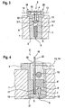
- a luminous element 2 is installed in a corresponding bore.
- This luminous element 2 comprises a plastic molding 3, which has a bore 4, which has a large diameter in the upper area, then a mean diameter and in the lower short, the interior 5 of the aircraft cabin area facing a very small diameter of about 1 mm.
- a light-emitting diode 6 is inserted so that it is held by the transition from the region with the wide diameter in the region with the average diameter of the bore approximately in the middle of the molding 3 (stages 3.1 and 3.2) ,
- a translucent lens body 7 made of transparent plastic is fitted, which has a lens-shaped upwardly curved light entrance surface 8 and a planar light exit surface 9.
- the arrangement of LED 6 and lens body 7 and the shape of the light entry surface 8 are formed such that the light emitted from the light emitting diode 6 (see beam path 10) is focused and directed to the light exit surface 9 of the lens body 7.
- the electrical connection of the light-emitting diode 6 takes place via its connection pins 11 and 12 and via cables 13 and 14 soldered or welded thereto.
- the light-emitting diode 6 is fixed with its legs 11 and 12 on a printed circuit board 15 and wired.
- This printed circuit board also carries, inter alia, an ESD protection diode 16 and is inserted into a guide 17, which is formed in the plastic molded part 13.
- the guide 17 has a stop 18 which by a defined positioning of the circuit board 15th in the luminous element 2 ensures that the light-emitting diode 6 is arranged at the optimum distance and in optimal positioning relative to the lens body 7.
- the circuit board 15 is not parallel, but aligned perpendicular to the optical axis.
- the attached with their legs 11 and 12 on the circuit board 15 and connected light emitting diode 6 is on the steps 3.1 and 3.2 in the bore 4 in the molding 3 on.
- the molded body 3 integrally formed latching hooks 19 and 20 engage behind the circuit board 15 and thus prevent falling out of the printed circuit board 15 and LED 6 from the luminous element 2.
- the connecting cables 13 and 14 are guided past the latching hooks 19 and 20.
- the molded body 3 and the lens body 7 in one piece in the form of a luminous element body 21, which consists as a whole of translucent plastic executed.
- an SMD LED 6 ' is used as the light source, which has a lateral light emission.
- the connection cables 13 and 14 are guided through bores or recesses in the luminous element body 21.
- the free interior in the light-emitting element body 21 is sealed with vinegar-free silicone as potting compound 22.
- the circuit board 15 has at its upper end a pullout hole 23, with which the circuit board 15 together with light emitting diode 6 ', applied electronics 16 and connecting cables 13, 14 and the potting compound 22 can be pulled out of the light-emitting element body 21.
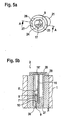
- FIG. 5a the luminous element body 21 of a further embodiment of the luminous element 2 is shown in a perspective view.
- This guide 24, like the guide 17, has a stop 25 for the defined positioning of the light-emitting diode 6 'relative to the light entry surface 8 of the light-emitting element body 21.
- the cable exit recesses 26 and 27 are visible.
- FIG. 5b the complete luminous element 2 is made using the luminous element body 21 FIG. 5a shown in cross section along the line AA.
- On the circuit board 15 is a suppression or drive electronics 16 'for the SMD LED 6' attached and interconnected.
- the interior of the luminous element 2 or of the luminous element body 21 is closed by an end cap 28.
- the luminous element body 21 is adhesively bonded in a bushing 29, which is glued into a bore in the aircraft cabin ceiling 1.
- the bush 29 has in the middle and upper part of a wide bore for receiving the luminous element body 21, in the lowermost part, however, only a very narrow bore, which only allows the passage of the light exit portion 30 of the luminous element body 21.
- the luminous element may be e.g. be arranged flush both with respect to the top and with respect to the underside of the ceiling panels of the aircraft cabin, the light exit surface of the luminous element, the end face of the socket and the surface of the ceiling panels are preferably in turn arranged flush with each other.
- the light exit surface of the luminous element can be made flat or roughened. With the latter it is achieved that the light emerging from the luminous element is scattered in different directions, as a result of which the luminous spot caused by the light exit surface is visible from all directions (ie also at very flat viewing angles) from the interior 5 of the aircraft cabin.
Landscapes
- Engineering & Computer Science (AREA)
- Mechanical Engineering (AREA)
- Physics & Mathematics (AREA)
- General Engineering & Computer Science (AREA)
- General Physics & Mathematics (AREA)
- Optics & Photonics (AREA)
- Non-Portable Lighting Devices Or Systems Thereof (AREA)
- Led Device Packages (AREA)
- Illuminated Signs And Luminous Advertising (AREA)
- Arrangements Of Lighting Devices For Vehicle Interiors, Mounting And Supporting Thereof, Circuits Therefore (AREA)
Description
- Die Erfindung betrifft ein Leuchtelement mit einem Leuchtmittel, vorzugsweise einer Leuchtdiode, nach dem Oberbegriff des Patentanspruchs 1.
- Aus der
DE 198 43 330 A1 ist eine Flugzeugkabinen-Beleuchtung bekannt, welche aus mehreren, an oder in der Decke einer Flugzeugkabine angebrachten, punktförmigen Lichtquellen besteht, wobei die punktförmigen Lichtquellen mindestens eine Leuchtdiode aufweisen, welche ihr Licht direkt in das Innere der Flugzeugkabine abstrahlen. - In der
DE 196 32 699 A1 ist eine Orientierungsanzeige auf Lichtleiterbasis offenbart, bei welcher Lichtleiter von mindestens zwei Leuchtdioden angestrahlt werden und Oberflächenveränderungen an der Längsseite des Lichtleiters zu einer Abgabe von Licht in Form von Strichen, Linien, Punkten, Symbolen u. a. zum Zweck einer Markierung führen. - In der
DE 41 42 175 A1 ist eine Anzeigeeinrichtung für Flugzeuge beschrieben, welche flache Lichtleitelemente aufweist, in deren Rand Leuchtdioden in Reihen angeordnet sind. - Die Leuchtelemente nach dem genannten Stand der Technik haben den Nachteil, dass ihre leuchtende Fläche eine bestimmte Mindestgröße hat.
- Aus der
JP 63-052491 A JP-06-007509 - Aus der
JP 02-301902 A - Dieser genannte Stand der Technik hat den Nachteil, dass die Leuchtdiode in dem Leuchtelement entweder gar nicht oder aber derart befestigt ist, dass sie bei einem Defekt nicht ohne größeren Aufwand ausgetauscht werden kann.
- Es ist nun Aufgabe der Erfindung, ein einfach aufgebautes Leuchtelement mit kleiner leuchtender Fläche zu schaffen, bei dem der Austausch des Leuchtmittels ohne großen Aufwand möglich ist.
- Diese Aufgabe wird von einem Leuchtelement mit den Merkmalen des Patentanspruchs 1 erfüllt. Vorteilhafte Ausgestaltungen und Weiterbildungen der Erfindung ergeben sich aus den abhängigen Ansprüchen.
- Nach der Erfindung weist ein gattungsgemäßes Leuchtelement einen lichtdurchlässigen Linsenkörper, vorzugsweise aus einem transparenten Kunststoff wie z.B. Polycarbonat, mit einer linsenförmigen Lichteintrittsfläche und mit einer Lichtaustrittsfläche auf, wobei die Lichtaustrittsfläche beliebig klein, auf jeden Fall aber kleiner als die Lichteintrittsfläche ist.
- Dadurch wird erreicht, dass die leuchtende Fläche des Leuchtelements beliebig klein gestaltet sein kann, vor allem auch kleiner als das Leuchtmittel selbst.
- Das Leuchtmittel ist nun zumindest teilweise mit Silikon in dem Leuchtelement vergossen und so in diesem lösbar befestigt sein.
- Vorzugsweise ist die Lichteintrittsfläche des Linsenkörpers derart geformt, dass das von dem Leuchtmittel in den Linsenkörper eindringende Licht auf die Lichtaustrittsfläche gelenkt wird. Durch diese Fokussierung wird erreicht, dass die leuchtende Fläche trotz ihrer geringen Ausdehnung ausreichend hell leuchtet.
- Weiterhin kann vorgesehen sein, dass das Leuchtelement derart in den Leuchtenträger eingebaut ist, dass die Lichtaustrittsfläche des Linsenkörpers bündig mit der Oberfläche des Leuchtenträgers ist, wodurch erreicht wird, dass die Lichtaustrittsfläche bei ausgeschaltetem Leuchtmittel nahezu unsichtbar ist.
- Die Lichtaustrittsfläche des Linsenkörpers kann überdies plan und/oder angeraut ("angeschliffen") sein und kreisförmig, drei- oder mehreckig oder auch in beliebiger anderer Form ausgeführt sein. Außerdem sollte das Leuchtmittel in dem Leuchtelement derart angeordnet sein, dass ein Großteil des von ihm ausgestrahlten Lichts auf die Lichteintrittsfläche des Linsenkörpers trifft.
- In Weiterbildung der Erfindung kann vorgesehen sein, dass das Leuchtmittel auf einer Leiterplatte befestigt und verschaltet ist, welche in dem Leuchtelement angeordnet und zumindest teilweise mit Silikon vergossen und lösbar befestigt ist, wobei das Leuchtmittel vorzugsweise als SMD-Leuchtdiode ausgeführt ist.
- Ebenso kann der Linsenkörper in einen Leuchtelementkörper integriert sein, welcher aus demselben Material besteht wie der Linsenkörper und welcher das Leuchtmittel aufnimmt. Vorzugsweise sind dabei Linsenkörper und Leuchtelementkörper einstückig ausgeführt.
- In Ausgestaltung der Erfindung ist vorgesehen, dass das Leuchtelement bzw. der Leuchtelementkörper eine vorzugsweise mit Anschlag ausgestattete Führung für das Leuchtmittel und/oder für die Leiterplatte und/oder eine Ausnehmung für die Zuführung eines elektrischen Kabels in das Leuchtelement bzw. den Leuchtelementkörper aufweist.
- Eine weitere Ausgestaltung der Erfindung sieht vor, dass das Leuchtelement bzw. der Leuchtelementkörper in einer Buchse gehaltert sind, wobei die Buchse in dem Leuchtenträger eingebaut ist. Dabei sind die Lichtaustrittsfläche des Linsenkörpers, die Stirnfläche der Buchse und die Oberfläche des Leuchtenträgers bündig zueinander, um die Lichtaustrittsfläche bei ausgeschaltetem Leuchtelement nahezu unsichtbar zu machen.
- Das Leuchtelement bzw. die Buchse können im Leuchtenträger verklebt sein. Als Leuchtenträger kann die Decke oder Wand einer Flugzeugkabine dienen. Die Leuchtdiode strahlt vorzugsweise weißes Licht ab und kann mit gleichmäßiger Helligkeit, blinkend oder auch flackernd (heller leuchtend - dunkler leuchtend) betrieben werden. Das Leuchtelement kann Teil einer Sternenhimmel-Beleuchtung sein.
- Anhand der Zeichnungen soll im folgenden die Erfindung näher erläutert werden. Es zeigen:
- Figur 1
- ein erstes Ausführungsbeispiel eines eingebauten Leuchtelements nach dem Stand der Technik im Querschnitt,
- Figur 2
- ein zweites Ausführungsbeispiel nach dem Stand der Technik,
- Figur 3
- ein drittes Ausführungsbeispiel nach dem Stand der Technik,
- Figur 4
- ein Ausführungsbeispiel gemäß der Erfindung,
- Figur 5a
- einen Leuchtelementkörper eines weiteren Ausführungsbeispiels nach dem Stand der Technik in perspektivischer Ansicht und
- Figur 5b
- das Leuchtelement des Ausführungsbeispiels von
Figur 5a im Quer- schnitt entlang der Linie A-A. - In einer Deckenpanele 1 einer Flugzeugkabine ist in einer entsprechenden Bohrung ein Leuchtelement 2 eingebaut. Dieses Leuchtelement 2 umfasst ein Kunststoffformteil 3, welches eine Bohrung 4 aufweist, die im oberen Bereich einen großen Durchmesser, daran anschließend einen mittleren Durchmesser und im unteren kurzen, dem Innenraum 5 der Flugzeugkabine zugewandten Bereich einen sehr kleinen Durchmesser von etwa 1 mm aufweist. In die Bohrung 4 des Kunststoffformkörpers 3 ist eine Leuchtdiode 6 derart eingesetzt, dass sie durch den Übergang von dem Bereich mit dem weiten Durchmesser in den Bereich mit dem mittleren Durchmesser der Bohrung etwa in der Mitte des Formkörpers 3 (Stufen 3.1 und 3.2) gehalten wird. Unterhalb der Leuchtdiode ist in der Bohrung 4 ein lichtdurchlässiger Linsenkörper 7 aus transparentem Kunststoff eingepasst, der eine linsenförmig nach oben gewölbte Lichteintrittsfläche 8 und eine plane Lichtaustrittsfläche 9 aufweist. Die Anordnung von Leuchtdiode 6 und Linsenkörper 7 sowie die Form der Lichteintrittsfläche 8 sind derart ausgebildet, dass das von der Leuchtdiode 6 ausgestrahlte Licht (siehe Strahlengang 10) gebündelt und zur Lichtaustrittsfläche 9 des Linsenkörpers 7 gelenkt wird. Der elektrische Anschluss der Leuchtdiode 6 erfolgt über deren Anschlussbeinchen 11 und 12 sowie über daran angelötete bzw. angeschweißte Kabel 13 und 14.
- Bei dem Ausführungsbeispiel gemäß
Figur 2 ist die Leuchtdiode 6 mit ihren Beinchen 11 und 12 auf einer Leiterplatte 15 befestigt und verdrahtet. Diese Leiterplatte trägt weiterhin u.a. eine ESD-Schutzdiode 16 und ist in eine Führung 17 gesteckt, welche im Kunststoffformteil 13 ausgebildet ist. Die Führung 17 weist einen Anschlag 18 auf, der durch eine definierte Positionierung der Leiterplatte 15 im Leuchtelement 2 dafür sorgt, dass die Leuchtdiode 6 im optimalen Abstand und in optimaler Positionierung gegenüber dem Linsenkörper 7 angeordnet ist. - Im Ausführungsbeispiel gemäß
Figur 3 ist die Leiterplatte 15 nicht parallel, sondern senkrecht zur optischen Achse ausgerichtet. Die mit ihren Beinchen 11 und 12 auf der Leiterplatte 15 befestigte und verschaltete Leuchtdiode 6 steht auf den Stufen 3.1 und 3.2 in der Bohrung 4 im Formkörper 3 auf. Am Formkörper 3 einstückig angeformte Rasthaken 19 und 20 hintergreifen die Leiterplatte 15 und verhindern so ein Herausfallen von Leiterplatte 15 und Leuchtdiode 6 aus dem Leuchtelement 2. Die Anschlusskabel 13 und 14 sind an den Rasthaken 19 und 20 vorbei geführt. - Im Ausführungsbeispiel gemäß
Figur 4 sind der Formkörper 3 und der Linsenkörper 7 einstückig in Form eines Leuchtelementkörpers 21, der als Ganzes aus lichtdurchlässigem Kunststoff besteht, ausgeführt. Darüber hinaus ist als Leuchtmittel eine SMD-Leuchtdiode 6' verwendet, welche eine seitliche Lichtabstrahlung besitzt. Die Anschlusskabel 13 und 14 sind durch Bohrungen bzw. Ausnehmungen im Leuchtelementkörper 21 hindurch geführt. Der freie Innenraum im Leuchtelementkörper 21 ist mit essigfreiem Silikon als Vergussmasse 22 versiegelt. Die Leiterplatte 15 weist an ihrem oberen Ende ein Auszugsloch 23 auf, mit dem die Leiterplatte 15 samt Leuchtdiode 6', aufgebrachter Elektronik 16 und Anschlusskabeln 13, 14 sowie der Vergussmasse 22 aus dem Leuchtelementkörper 21 herausgezogen werden kann. Somit ist ein Austausch der Leuchtdiode 6' auf einfache Weise möglich. - In
Figur 5a ist der Leuchtelementkörper 21 eines weiteren Ausführungsbeispiels des Leuchtelements 2 in perspektivischer Darstellung gezeigt. Man erkennt die Führung 17 für die Leiterplatte 15 sowie eine Führung 24 für die SMD-Leuchtdiode 6'. Diese Führung 24 besitzt ebenso wie die Führung 17 einen Anschlag 25 zur definierten Positionierung der Leuchtdiode 6' gegenüber der Lichteintrittsfläche 8 des Leuchtelementkörpers 21. Ebenso sind die Kabelaustritts-Ausnehmungen 26 und 27 sichtbar. - In
Figur 5b ist das komplette Leuchtelement 2 unter Verwendung des Leuchtelementkörpers 21 ausFigur 5a im Querschnitt entlang der Linie A-A gezeigt. Auf der Leiterplatte 15 ist eine Entstör- bzw. Ansteuerungselektronik 16' für die SMD-Leuchtdiode 6' befestigt und verschaltet. Der Innenraum des Leuchtelements 2 bzw. des Leuchtelementkörpers 21 ist durch eine Abschlusskappe 28 verschlossen. Der Leuchtelementkörper 21 ist in einer Buchse 29 verklebt, welche in eine Bohrung in der Flugzeugkabinendecke 1 geklebt ist. Die Buchse 29 hat im mittleren und oberen Teil eine weite Bohrung zur Aufnahme des Leuchtelementkörpers 21, im untersten Teil jedoch nur eine sehr schmale Bohrung, die lediglich den Durchtritt des Lichtaustrittsabschnitts 30 des Leuchtelementkörpers 21 zulässt. - Die in den verschiedenen Ausführungsbeispielen aufgezeigten Merkmale können beliebig miteinander kombiniert werden, ohne dass der Umfang der Erfindung verlassen wird. So kann das Leuchtelement z.B. sowohl bezüglich der Oberseite als auch bezüglich der Unterseite der Deckenpanele der Flugzeugkabine bündig angeordnet sein, wobei die Lichtaustrittsfläche des Leuchtelements, die Stirnfläche der Buchse und die Oberfläche der Deckenpanele vorzugsweise wiederum bündig zueinander angeordnet sind. Die Lichtaustrittsfläche des Leuchtelements kann plan oder auch angeraut ausgeführt sein. Mit letzterem wird erreicht, dass das aus dem Leuchtelement austretende Licht in verschiedene Richtungen gestreut wird, wodurch der durch die Lichtaustrittsfläche hervorgerufene Leuchtpunkt aus allen Richtungen (also auch unter sehr flachen Betrachtungswinkeln) aus dem Innenraum 5 der Flugzeugkabine sichtbar ist.
Claims (11)
- Leuchtelement (2) mit einem Leuchtmittel (6,6'), vorzugsweise einer Leuchtdiode (LED), wobei das Leuchtelement (2) in einen Leuchtenträger (1) einbaubar ist und einen lichtdurchlässigen Linsenkörper (7) mit einer linsenförmigen Lichteintrittsfläche (8) und mit einer Lichtaustrittsfläche (9) aufweist, wobei die Lichtaustrittsfläche (9) kleiner als die Lichteintrittsfläche (8) ist,
dadurch gekennzeichnet,
dass das Leuchtmittel (6,6') zumindest teilweise mit Silikon (22) in dem Leuchtelement (2) vergossen und in diesem lösbar befestigt ist. - Leuchtelement nach Anspruch 1,
dadurch gekennzeichnet,
dass die Lichteintrittsfläche (8) derart geformt ist, dass das von dem Leuchtmittel (6,6') in den Linsenkörper (7) eindringende Licht auf die Lichtaustrittsfläche (9) gelenkt wird. - Leuchtelement nach Anspruch 1 oder 2,
dadurch gekennzeichnet,
dass das Leuchtmittel (6,6') in dem Leuchtelement (2) derart angeordnet ist, dass ein Großteil des von ihm ausgestrahlten Lichts auf die Lichteintrittsfläche (8) des Linsenkörpers (7) trifft. - Leuchtelement nach einem der Ansprüche 1 bis 3,
dadurch gekennzeichnet,
dass das Leuchtelement (2) derart in den Leuchtenträger (1) eingebaut ist, dass die Lichtaustrittsfläche (9) des Linsenkörpers (7) bündig mit der Oberfläche des Leuchtenträgers (1) ist. - Leuchtelement nach einem der vorherigen Ansprüche,
dadurch gekennzeichnet,
dass der Linsenkörper (7) aus transparentem Kunststoff besteht und die Lichtaustrittsfläche (9) des Linsenkörpers (7) plan und/oder angeraut ist. - Leuchtelement nach einem der vorherigen Ansprüche,
dadurch gekennzeichnet,
dass das Leuchtmittel (6,6') auf einer Leiterplatte (15) befestigt und verschaltet ist, welche in dem Leuchtelement (2) angeordnet und zumindest teilweise mit Silikon (22) vergossen und lösbar befestigt ist, wobei das Leuchtmittel (6,6') vorzugsweise als SMD-Leuchtdiode ausgeführt ist. - Leuchtelement nach einem der vorherigen Ansprüche,
dadurch gekennzeichnet,
dass der Linsenkörper (7) in einen Leuchtelementkörper (21) integriert ist, welcher aus demselben Material besteht wie der Linsenkörper (7) und welcher das Leuchtmittel (6,6') aufnimmt, wobei Linsenkörper (7) und Leuchtelementkörper (21) vorzugsweise einstückig ausgeführt sind. - Leuchtelement nach einem der vorherigen Ansprüche,
dadurch gekennzeichnet,
dass das Leuchtelement (2) bzw. der Leuchtelementkörper (21) eine Führung (24), vorzugsweise mit Anschlag, für das Leuchtmittel (6,6') und/oder eine Führung (17), vorzugsweise mit Anschlag (18), für die Leiterplatte (15) und/oder eine Ausnehmung (26,27) für die Zuführung eines elektrischen Kabels (13,14) in das Leuchtelement (2) bzw. den Leuchtelementkörper (21) aufweist. - Leuchtelement nach einem der vorherigen Ansprüche,
dadurch gekennzeichnet,
dass das Leuchtelement (2) bzw. der Leuchtelementkörper (21) in einer Buchse (29) gehaltert sind, welche in dem Leuchtenträger (1) eingebaut ist, wobei vorzugsweise die Lichtaustrittsfläche (9) des Linsenkörpers (7), die Stirnfläche der Buchse (29) und die Oberfläche des Leuchtenträgers (1) bündig sind. - Leuchtelement nach Anspruch 9,
dadurch gekennzeichnet,
dass das Leuchtelement (2) bzw. die Buchse (29) im Leuchtenträger (1) verklebt ist. - Leuchtelement nach einem der vorherigen Ansprüche,
dadurch gekennzeichnet,
dass der Leuchtenträger (1) die Decke oder Wand einer Flugzeugkabine ist, dass die Leuchtdiode (6,6') weißes Licht abstrahlt und/oder dass das Leuchtelement (2) Teil einer Sternenhimmel-Beleuchtung ist.
Applications Claiming Priority (2)
| Application Number | Priority Date | Filing Date | Title |
|---|---|---|---|
| DE10331075 | 2003-07-09 | ||
| DE10331075A DE10331075B4 (de) | 2003-07-09 | 2003-07-09 | Leuchtelement mit einem Leuchtmittel |
Publications (3)
| Publication Number | Publication Date |
|---|---|
| EP1495910A2 EP1495910A2 (de) | 2005-01-12 |
| EP1495910A3 EP1495910A3 (de) | 2008-04-16 |
| EP1495910B1 true EP1495910B1 (de) | 2011-04-06 |
Family
ID=33441683
Family Applications (1)
| Application Number | Title | Priority Date | Filing Date |
|---|---|---|---|
| EP04015568A Expired - Lifetime EP1495910B1 (de) | 2003-07-09 | 2004-07-02 | Leuchtelement mit einem Leuchtmittel |
Country Status (3)
| Country | Link |
|---|---|
| US (1) | US7264383B2 (de) |
| EP (1) | EP1495910B1 (de) |
| DE (2) | DE10331075B4 (de) |
Families Citing this family (19)
| Publication number | Priority date | Publication date | Assignee | Title |
|---|---|---|---|---|
| DE102007029140B4 (de) | 2007-06-25 | 2009-10-01 | Airbus Deutschland Gmbh | Innenausstattungspaneel mit mindestens einem Beleuchtungselement und Verfahren zur Herstellung eines derartigen Innenausstattungspaneels |
| DE102007040573A1 (de) * | 2007-08-28 | 2009-03-05 | Christian Bartenbach | Beleuchtungsvorrichtung |
| US7857484B2 (en) | 2007-08-31 | 2010-12-28 | The Boeing Company | Lighting panels including embedded illumination devices and methods of making such panels |
| US8033684B2 (en) * | 2007-08-31 | 2011-10-11 | The Boeing Company | Starry sky lighting panels |
| DE102008048835B4 (de) * | 2008-09-25 | 2011-12-01 | Airbus Operations Gmbh | Fixierungssystem zum lösbaren Fixieren einer Lichtquelle an einer Lichteintrittsfläche eines Lichtleitkörpers und zugehöriges Innenausstattungspaneel |
| JP5424457B2 (ja) * | 2009-02-05 | 2014-02-26 | 矢崎総業株式会社 | プリズム付き車両用照明器具 |
| US8944658B1 (en) * | 2009-09-11 | 2015-02-03 | The Boeing Company | LED holder for lighting panels |
| DE102010015230A1 (de) * | 2010-04-15 | 2011-10-20 | Agabekov Sa | Blendschutzvorrichtung für Lichtelemente |
| DE102010036101B4 (de) * | 2010-09-01 | 2014-02-27 | Diehl Aerospace Gmbh | Kabelbaum und Innenausstattungselement |
| DE102012009264A1 (de) * | 2011-05-19 | 2012-11-22 | Marquardt Mechatronik Gmbh | Beleuchtung für ein Hausgerät |
| FR2978379B1 (fr) * | 2011-07-29 | 2014-03-14 | Saint Gobain | Vitrage lumineux de vehicule, fabrication |
| DE102011082343B4 (de) * | 2011-09-08 | 2015-04-09 | Lisa Dräxlmaier GmbH | Dekorverbund mit einer Dekorschicht und einer Licht leitenden Schicht |
| DE102012104580B4 (de) * | 2012-05-29 | 2014-05-22 | Ralf-Thorsten Henning | Flächenhaftes Leuchtobjekt und Verfahren zu seiner Herstellung |
| DE102012023654A1 (de) | 2012-11-28 | 2014-05-28 | GM Global Technology Operations LLC (n. d. Gesetzen des Staates Delaware) | Lichtadaptereinrichtung, LED-Modul, LED-Einrichtung, Zubehöreinheit, Kraft-fahrzeug und Verfahren hierzu |
| WO2018083770A1 (ja) * | 2016-11-02 | 2018-05-11 | 河西工業株式会社 | 照明構造 |
| EP3549412B1 (de) | 2016-11-30 | 2022-10-05 | Tactotek Oy | Beleuchtungsstruktur und entsprechendes herstellungsverfahren |
| US10544934B1 (en) * | 2018-01-26 | 2020-01-28 | Nicholas A. Kennedy | Illuminating hub assembly for a quoit board |
| US10364965B1 (en) * | 2018-04-16 | 2019-07-30 | The Boeing Company | System and fastener for coupling a light-emitting device to a composite panel assembly |
| EP4431400B1 (de) * | 2023-03-14 | 2025-10-01 | Goodrich Lighting Systems GmbH & Co. KG | Flugzeugleuchte, flugzeug mit einer flugzeugleuchte und verfahren zur herstellung einer flugzeugleuchte |
Family Cites Families (22)
| Publication number | Priority date | Publication date | Assignee | Title |
|---|---|---|---|---|
| US4363087A (en) * | 1981-01-22 | 1982-12-07 | Illinois Tool Works Inc. | Mounting post for holding a lighted electrical pushbutton switch |
| US4471414A (en) * | 1982-03-11 | 1984-09-11 | Savage John Jun | Integrated light unit and circuit element attachable to circuit board |
| JPS6352491A (ja) * | 1986-08-22 | 1988-03-05 | Hitachi Ltd | パツケ−ジ部品およびこれを用いた光電子装置 |
| JPH02301902A (ja) * | 1989-05-16 | 1990-12-14 | Endo Shomei:Kk | 埋込み型照明灯具とその埋込み方法 |
| DE4142175A1 (de) | 1991-12-20 | 1993-06-24 | Hella Kg Hueck & Co | Anzeigeeinrichtung fuer flugzeuge |
| JPH0697599A (ja) | 1992-09-10 | 1994-04-08 | Furukawa Electric Co Ltd:The | 半導体レーザアレイおよびその実装方法 |
| JPH0697509A (ja) * | 1992-09-16 | 1994-04-08 | Mitsubishi Electric Corp | 光半導体装置 |
| US5463502A (en) * | 1994-05-16 | 1995-10-31 | Savage, Jr.; John M. | Lens assembly for use with LEDs |
| JPH08115610A (ja) * | 1994-10-13 | 1996-05-07 | Alpine Electron Inc | 照光装置 |
| US6280048B1 (en) * | 1995-03-07 | 2001-08-28 | L. Hanson Luquire | Portable multipurpose viewing apparatus |
| JP3726308B2 (ja) * | 1995-06-14 | 2005-12-14 | 凸版印刷株式会社 | 検版装置 |
| DE19630240A1 (de) * | 1996-07-26 | 1998-01-29 | Hella Kg Hueck & Co | Einkopplungseinheit zum Einkoppeln von Licht |
| DE29613798U1 (de) * | 1996-08-09 | 1996-11-07 | MENTOR GmbH & Co Präzisions-Bauteile, 40699 Erkrath | Element zum Beleuchten, Ausleuchten und Anzeigen (Kfz - Orientierungsbeleuchtung) |
| DE19632699A1 (de) | 1996-08-14 | 1998-02-19 | Mentor Gmbh & Co Praezisions B | Orientierungsanzeige auf Lichtleiterbasis |
| US5738437A (en) * | 1996-08-27 | 1998-04-14 | Ilagan; Artemio M. | Attachment for light fixture cover |
| AT408284B (de) * | 1998-01-19 | 2001-10-25 | Swarco Futurit Verkehrssignals | Optikeinheit für signal-, verkehrs- und anzeigegeräte und verfahren zur herstellung einer prägung |
| US6127910A (en) * | 1998-06-05 | 2000-10-03 | Topworx, Inc. | Hermetically sealed proximity switch |
| DE19843330C2 (de) * | 1998-09-22 | 2003-10-16 | Diehl Stiftung & Co | Fahrzeugkabinenbeleuchtung |
| US6290368B1 (en) * | 1999-05-21 | 2001-09-18 | Robert A. Lehrer | Portable reading light device |
| US6612725B2 (en) * | 2001-03-30 | 2003-09-02 | Itc Incorporated | Lamp assembly with selectively positionable bulb |
| US20040264196A1 (en) * | 2003-06-30 | 2004-12-30 | Kuo-Fen Shu | LED spotlight (type I) |
| DE10331076B4 (de) * | 2003-07-09 | 2011-04-07 | Airbus Operations Gmbh | Leuchtelement mit einer Leuchtdiode |
-
2003
- 2003-07-09 DE DE10331075A patent/DE10331075B4/de not_active Expired - Fee Related
-
2004
- 2004-07-02 DE DE502004012369T patent/DE502004012369D1/de not_active Expired - Lifetime
- 2004-07-02 EP EP04015568A patent/EP1495910B1/de not_active Expired - Lifetime
- 2004-07-08 US US10/888,715 patent/US7264383B2/en not_active Expired - Lifetime
Also Published As
| Publication number | Publication date |
|---|---|
| EP1495910A2 (de) | 2005-01-12 |
| DE502004012369D1 (de) | 2011-05-19 |
| EP1495910A3 (de) | 2008-04-16 |
| US7264383B2 (en) | 2007-09-04 |
| US20050007791A1 (en) | 2005-01-13 |
| DE10331075A1 (de) | 2005-02-10 |
| DE10331075B4 (de) | 2009-02-26 |
Similar Documents
| Publication | Publication Date | Title |
|---|---|---|
| DE10331075B4 (de) | Leuchtelement mit einem Leuchtmittel | |
| EP2738447B1 (de) | Regalbeleuchtungsvorrichtung | |
| EP1496380B1 (de) | Leuchtelement mit einer Leuchtdiode | |
| DE102014211874B4 (de) | Beleuchtungseinrichtung eines Kraftfahrzeugs | |
| DE102004063574A1 (de) | Leuchtvorrichtung mit mehreren Halbleiterlichtquellen | |
| AT500013B1 (de) | Optikelement für wechselverkehrszeichen | |
| EP2023035A1 (de) | Leuchte | |
| EP1227458A2 (de) | Anzeige- und/oder Signalsiervorrichtung | |
| DE102005019018A1 (de) | Leuchte mit wenigstens einem Lichtleiter und mehreren Lichtquellen | |
| EP2796769B1 (de) | LED-Leuchte mit einer Lichtleiter-Anordnung | |
| EP3179159B1 (de) | Gartenleuchte | |
| EP3853518B1 (de) | Lichtmodul, insbesondere zur verwendung in einer beleuchtungsvorrichtung für ein kraftfahrzeug | |
| EP2603732A1 (de) | Anordnung zur lichtabgabe mit lichtlenkelement und reflektor | |
| DE102020201645A1 (de) | Beleuchtungsvorrichtung für ein Kraftfahrzeug | |
| DE102015106242B4 (de) | Begrenzungsleuchte für Fahrzeuge | |
| DE112019001649T5 (de) | Elektrische vorrichtung für ein fahrzeugtrittbrett | |
| DE202011005334U1 (de) | Lichtleitvorrichtung für Leuchtdiodenbirne | |
| DE102018218441B4 (de) | Flächenleuchtelement und Innenausstattungselement für ein Kraftfahrzeug mit einem Flächenleuchtelement | |
| DE10348994A1 (de) | Windkraftanlage mit Leuchtanlage | |
| EP1275899B1 (de) | Downlight mit Seitenreflektor | |
| EP1031125B1 (de) | Informationsanzeige | |
| DE202023107494U1 (de) | Signaleinrichtung bei einer Leuchte und Leuchte | |
| EP2246612B1 (de) | LED-Leuchte | |
| AT413612B (de) | Beleuchtete hinweistafel | |
| DE102020201644A1 (de) | Beleuchtungsvorrichtung für ein Kraftfahrzeug |
Legal Events
| Date | Code | Title | Description |
|---|---|---|---|
| PUAI | Public reference made under article 153(3) epc to a published international application that has entered the european phase |
Free format text: ORIGINAL CODE: 0009012 |
|
| AK | Designated contracting states |
Kind code of ref document: A2 Designated state(s): AT BE BG CH CY CZ DE DK EE ES FI FR GB GR HU IE IT LI LU MC NL PL PT RO SE SI SK TR |
|
| AX | Request for extension of the european patent |
Extension state: AL HR LT LV MK |
|
| RAP1 | Party data changed (applicant data changed or rights of an application transferred) |
Owner name: DIEHL AEROSPACE GMBH |
|
| PUAL | Search report despatched |
Free format text: ORIGINAL CODE: 0009013 |
|
| AK | Designated contracting states |
Kind code of ref document: A3 Designated state(s): AT BE BG CH CY CZ DE DK EE ES FI FR GB GR HU IE IT LI LU MC NL PL PT RO SE SI SK TR |
|
| AX | Request for extension of the european patent |
Extension state: AL HR LT LV MK |
|
| RIC1 | Information provided on ipc code assigned before grant |
Ipc: B64D 11/00 20060101ALI20080311BHEP Ipc: F21Y 101/02 20060101ALN20080311BHEP Ipc: H01L 33/00 20060101ALI20080311BHEP Ipc: F21W 101/08 20060101ALN20080311BHEP Ipc: F21V 5/04 20060101ALI20080311BHEP Ipc: B60Q 3/02 20060101AFI20041004BHEP |
|
| 17P | Request for examination filed |
Effective date: 20080607 |
|
| 17Q | First examination report despatched |
Effective date: 20080819 |
|
| AKX | Designation fees paid |
Designated state(s): DE FR GB |
|
| GRAP | Despatch of communication of intention to grant a patent |
Free format text: ORIGINAL CODE: EPIDOSNIGR1 |
|
| GRAS | Grant fee paid |
Free format text: ORIGINAL CODE: EPIDOSNIGR3 |
|
| GRAA | (expected) grant |
Free format text: ORIGINAL CODE: 0009210 |
|
| AK | Designated contracting states |
Kind code of ref document: B1 Designated state(s): DE FR GB |
|
| REG | Reference to a national code |
Ref country code: GB Ref legal event code: FG4D Free format text: NOT ENGLISH |
|
| REF | Corresponds to: |
Ref document number: 502004012369 Country of ref document: DE Date of ref document: 20110519 Kind code of ref document: P |
|
| REG | Reference to a national code |
Ref country code: DE Ref legal event code: R096 Ref document number: 502004012369 Country of ref document: DE Effective date: 20110519 |
|
| PLBE | No opposition filed within time limit |
Free format text: ORIGINAL CODE: 0009261 |
|
| STAA | Information on the status of an ep patent application or granted ep patent |
Free format text: STATUS: NO OPPOSITION FILED WITHIN TIME LIMIT |
|
| 26N | No opposition filed |
Effective date: 20120110 |
|
| REG | Reference to a national code |
Ref country code: DE Ref legal event code: R097 Ref document number: 502004012369 Country of ref document: DE Effective date: 20120110 |
|
| REG | Reference to a national code |
Ref country code: FR Ref legal event code: PLFP Year of fee payment: 12 |
|
| PGFP | Annual fee paid to national office [announced via postgrant information from national office to epo] |
Ref country code: FR Payment date: 20150626 Year of fee payment: 12 |
|
| PGFP | Annual fee paid to national office [announced via postgrant information from national office to epo] |
Ref country code: GB Payment date: 20150721 Year of fee payment: 12 |
|
| REG | Reference to a national code |
Ref country code: DE Ref legal event code: R079 Ref document number: 502004012369 Country of ref document: DE Free format text: PREVIOUS MAIN CLASS: B60Q0003020000 Ipc: B60Q0003200000 |
|
| GBPC | Gb: european patent ceased through non-payment of renewal fee |
Effective date: 20160702 |
|
| PG25 | Lapsed in a contracting state [announced via postgrant information from national office to epo] |
Ref country code: FR Free format text: LAPSE BECAUSE OF NON-PAYMENT OF DUE FEES Effective date: 20160801 |
|
| REG | Reference to a national code |
Ref country code: FR Ref legal event code: ST Effective date: 20170331 |
|
| PG25 | Lapsed in a contracting state [announced via postgrant information from national office to epo] |
Ref country code: GB Free format text: LAPSE BECAUSE OF NON-PAYMENT OF DUE FEES Effective date: 20160702 |
|
| PGFP | Annual fee paid to national office [announced via postgrant information from national office to epo] |
Ref country code: DE Payment date: 20200916 Year of fee payment: 17 |
|
| REG | Reference to a national code |
Ref country code: DE Ref legal event code: R119 Ref document number: 502004012369 Country of ref document: DE |
|
| PG25 | Lapsed in a contracting state [announced via postgrant information from national office to epo] |
Ref country code: DE Free format text: LAPSE BECAUSE OF NON-PAYMENT OF DUE FEES Effective date: 20220201 |