EP1494509A2 - Schaltungsanordnung zur Ansteuerung einer Hochdruckentladungslampe - Google Patents
Schaltungsanordnung zur Ansteuerung einer Hochdruckentladungslampe Download PDFInfo
- Publication number
- EP1494509A2 EP1494509A2 EP04013154A EP04013154A EP1494509A2 EP 1494509 A2 EP1494509 A2 EP 1494509A2 EP 04013154 A EP04013154 A EP 04013154A EP 04013154 A EP04013154 A EP 04013154A EP 1494509 A2 EP1494509 A2 EP 1494509A2
- Authority
- EP
- European Patent Office
- Prior art keywords
- voltage
- circuit arrangement
- ignition
- terminal
- pressure discharge
- Prior art date
- Legal status (The legal status is an assumption and is not a legal conclusion. Google has not performed a legal analysis and makes no representation as to the accuracy of the status listed.)
- Granted
Links
Images




Classifications
-
- H—ELECTRICITY
- H05—ELECTRIC TECHNIQUES NOT OTHERWISE PROVIDED FOR
- H05B—ELECTRIC HEATING; ELECTRIC LIGHT SOURCES NOT OTHERWISE PROVIDED FOR; CIRCUIT ARRANGEMENTS FOR ELECTRIC LIGHT SOURCES, IN GENERAL
- H05B41/00—Circuit arrangements or apparatus for igniting or operating discharge lamps
- H05B41/14—Circuit arrangements
- H05B41/26—Circuit arrangements in which the lamp is fed by power derived from DC by means of a converter, e.g. by high-voltage DC
- H05B41/28—Circuit arrangements in which the lamp is fed by power derived from DC by means of a converter, e.g. by high-voltage DC using static converters
- H05B41/288—Circuit arrangements in which the lamp is fed by power derived from DC by means of a converter, e.g. by high-voltage DC using static converters with semiconductor devices and specially adapted for lamps without preheating electrodes, e.g. for high-intensity discharge lamps, high-pressure mercury or sodium lamps or low-pressure sodium lamps
- H05B41/292—Arrangements for protecting lamps or circuits against abnormal operating conditions
-
- H—ELECTRICITY
- H05—ELECTRIC TECHNIQUES NOT OTHERWISE PROVIDED FOR
- H05B—ELECTRIC HEATING; ELECTRIC LIGHT SOURCES NOT OTHERWISE PROVIDED FOR; CIRCUIT ARRANGEMENTS FOR ELECTRIC LIGHT SOURCES, IN GENERAL
- H05B41/00—Circuit arrangements or apparatus for igniting or operating discharge lamps
- H05B41/02—Details
- H05B41/04—Starting switches
- H05B41/042—Starting switches using semiconductor devices
Definitions
- the return voltage of the high-pressure discharge lamp At ignition voltages up to 25 kV, the return voltage can be so high in particular directly after ignition, that they are assigned to the reflector of the Headlamps can skip. Due to the high voltages occurring results thereby the danger of Verletzunöcn for car mechanics or hobbyists, which coincidentally when the discharge lamp is switched on, the reflector is in contact. Due to the high temperatures - for example, is a typical value for the temperature of the discharge vessel 700 ° C, so that a return conductor located in the vicinity still remains heated to 550 ° C - no plastic insulation can be used.
- a third inductance in the electrical connection between the connection for supplying an ignition voltage and the associated connection arranged for the high-pressure discharge lamp, a third inductance, with the the first and the second inductance is magnetically coupled.
- the return conductor and the forward conductor connected via a diode branch. This one serves for safety.
- the lamp control gear electronic ballast, electronic ballast
- This interference current can through the third Winding be largely suppressed.
- the mode of action is based on that this measure the impedance for the interference current is also high at port 4.
- the output signals of the current-compensated choke 22 and the voltage applied to terminal 4 ignition voltage enter a block 24, the On the one hand an ignition circuit umtasst, on the other hand is designed so that its outputs 26 and 28, the high pressure discharge lamp 14 after ignition in operation with voltage can be supplied.
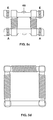
- FIG. 5 shows some embodiments of current-compensated chokes, as used in a device according to the invention Circuit arrangement can be used, wherein the respective Cores are wrapped for clarity with 2 windings.
- Figure 5a is a Ferrite core 46 provided with two windings, the first 30 and the second inductor 32nd the current-compensated throttle 22 form. The beginning of the winding is always A, the End marked with E. If a high-insulation ferrite is selected, wires can be used are wound, which are isolated from each other only by commercial cool insulating varnish. No additional carrier is needed, i. The wrapped ferrite core can be directly, for example in SMD technology, to be used in the circuit. This results in a clear Space saving.
- Figure 5b shows the use of a toroidal core 48 on which the two Windings are wound.
- Figure 5c another variant with ferrite core 46 is shown.
Landscapes
- Circuit Arrangements For Discharge Lamps (AREA)
Abstract
Description
- Figur 1
- eine Ausführungsform einer Hochdruckentladungslampe, wie sie beispielsweise in einem Scheinwerfer eines Kraftfahrzeugs eingesetzt wird:
- Figur 2
- in schematischer Darstellung ein erstes Ausführungsbeispiel einer erfindungsgemäßen Schaltungsanordnung;
- Figur 3
- das Ausführungsbeispiel von Figur 2 in detaillierterer Darstellung;
- Figur 4
- ein zweites Ausführungsbeispiel einer erfindungsgemäßen Schaltungsanordnung mit einer Drossel in der Zündleitung; und
- Figur 5
- verschiedene Ausführungsformen einer stromkompensierten Drossel zur Verwendung in einer erfindungsgemäßen Schaltungsanordnung.
- Figur 6
- Ausführungsform einer stromkompensierten Drossel zur Verwendung in einer erfindungsgemäßen Schaltungsanordnung mit speziellem Ringkern
Claims (12)
- Schaltungsanordnung zur Ansteuerung einer Hochdruckentladungslampe (14) miteinem Anschluss (1) für ein erstes Spannungspotential;einem Anschluss (2) für ein zweites Spannungspotential;einem Anschluss (4) zur Zuführung einer Zündspannung:dadurch gekennzeichnet, dass in der ersten elektrischen Verbindung eine zweite Induktivität (32) angeordnet ist, die zusammen mit der ersten Induktivität (30) eine stromkompensierte Drossel (22) (common mode choke) bildet.einer ersten elektrischen Verbindung, die an ihrem ersten Ende einen ersten Anschluss (26) für eine Hochdruckentladungslampe ( 14) bereitstellt und die an ihrem zweiten Ende mit dem Anschluss (1) für das erste Spannungspotential gekoppelt ist;einer zweiten elektrischen Verbindung, die an ihrem ersten Ende einen zweiten Anschluss (28) für eine Hochdruckentladungslampe (14) bereitstellt und die an ihrem zweiten Ende mit dem Anschluss (2) für das zweite Spannungspotential gekoppelt ist;einer ersten Induktivität (30), die in der zweiten elektrischen Verbindung angeordnet ist;einer Zündvorrichtung (24), die eingangsseitig zumindest an den Anschluss (4) zur Zuführung einer Zündspannung und die ausgangsseitig mit einem der Anschlüsse (26; 28) für die Hochdruckentladungslampe gekoppelt ist;
- Schaltungsanordnung nach Anspruch 1,
dadurch gekennzeichnet, dass das erste Spannungspotential eine Versorgungsspannung darstellt. - Schaltungsanordnung nach Anspruch 1 oder 2,
dadurch gekennzeichnet, dass das zweite Spannungspotential elektrische Masse darstellt. - Schaltungsanordnung nach einem der vorhergehenden Ansprüche,
dadurch gekennzeichnet, dass die erste elektrische Verbindung eine Hinleitung darstellt. - Schaltungsanordnung nach einem der vorhergehenden Ansprüche,
dadurch gekennzeichnet, dass die zweite elektrische Verbindung eine Rückteitung darstellt. - Schaltungsanordnung nach einem der vorhergehenden Ansprüche.
dadurch gekennzeichnet, dass das erste Spannungspotential vor der Zündung eine Gleichspannung, nach der Zündung eine Wechselspannung darstellt. - Schaltungsanordnung nach einem der vorhergehenden Ansprüche,
dadurch gekennzeichnet, dass die zweite Induktivität (32) zwischen dem Anschluss (1) für das erste Spannungspotential und der Zündvorrichtung (24) angeordnet ist. - Schaltungsanordnllng nach einem der Ansprüche 1 bis 6,
dadurch gekennzeichnet, dass die zweite Induktivität (32) zwischen der Zündvorrichtung (24) und dem Anschluss (26) für die Hochdruckentladunglampe (14) angeordnet ist, der an die Zündvorrichtung (24) gekoppelt ist. - Schaltungsanordnung nach einem der vorhergehenden Ansprüche.
dadurch gekennzeichnet, dass die erste (30) und die zweite Induktivität (32) Drähte umfassen, die auf einen gemeinsamen Ferritkern (46; 48)) gewickelt sind. - Schaltungsanordnung nach Anspruch 9,
dadurch gekennzeichnet. dass der Ferritkern (46; 48) aus hochisolierendem Material gefertigt ist. - Schaltungsanordnung nach einem der Ansprüche 9 oder 10,
dadurch gekennzeichnet, dass die Drähte als einzige Isolierung Isolierlack aufweisen. - Schlltungsanordnung nach einem der vorhergehenden Ansprüche,
dadurch gekennzeichnet. dass in der elektrischen Verbindung zwischen dem Anschluss (4) zur Zuführung einer Zündspannung und dem diesem Anschluss (4) zugeordneten Anschluss (26) für die Hochdruckentladungslampe (14) eine dritte Induktivität (31) angeordnet ist, die mit der ersten und der zweiten Induktivität (30; 32) magnetisch gekoppelt ist.
Applications Claiming Priority (2)
| Application Number | Priority Date | Filing Date | Title |
|---|---|---|---|
| DE10330117A DE10330117A1 (de) | 2003-07-03 | 2003-07-03 | Schaltungsanordnung zur Ansteuerung einer Hochdruckentladungslampe |
| DE10330117 | 2003-07-03 |
Publications (3)
| Publication Number | Publication Date |
|---|---|
| EP1494509A2 true EP1494509A2 (de) | 2005-01-05 |
| EP1494509A3 EP1494509A3 (de) | 2005-10-26 |
| EP1494509B1 EP1494509B1 (de) | 2007-10-10 |
Family
ID=33426851
Family Applications (1)
| Application Number | Title | Priority Date | Filing Date |
|---|---|---|---|
| EP04013154A Expired - Lifetime EP1494509B1 (de) | 2003-07-03 | 2004-06-03 | Schaltungsanordnung zur Ansteuerung einer Hochdruckentladungslampe |
Country Status (4)
| Country | Link |
|---|---|
| US (1) | US7019466B2 (de) |
| EP (1) | EP1494509B1 (de) |
| CA (1) | CA2472889A1 (de) |
| DE (2) | DE10330117A1 (de) |
Families Citing this family (6)
| Publication number | Priority date | Publication date | Assignee | Title |
|---|---|---|---|---|
| DE102004055976A1 (de) * | 2004-11-19 | 2006-05-24 | Patent-Treuhand-Gesellschaft für elektrische Glühlampen mbH | Schaltungsanordnung zum Betrieb einer Hochdruckentladungslampe |
| JP4574477B2 (ja) * | 2005-07-20 | 2010-11-04 | 株式会社リコー | 光走査装置及び画像形成装置 |
| EP1985160B1 (de) * | 2006-02-06 | 2009-11-25 | Philips Intellectual Property & Standards GmbH | Schaltungsanordnung und verfahren zum ansteuern einer hochdruck-gasentladungslampe |
| US7446488B1 (en) | 2007-08-29 | 2008-11-04 | Osram Sylvania | Metal halide lamp ballast controlled by remote enable switched bias supply |
| DE102008046163A1 (de) * | 2008-09-06 | 2010-03-11 | Hella Kgaa Hueck & Co. | Zündgerät mit Filter für eine Hochdruckgasentladungslampe |
| EP3130204B1 (de) * | 2014-04-07 | 2019-12-18 | Lumileds Holding B.V. | Treiberanordnung zum treiben einer hid lampe |
Family Cites Families (7)
| Publication number | Priority date | Publication date | Assignee | Title |
|---|---|---|---|---|
| US3732460A (en) * | 1972-01-28 | 1973-05-08 | Gen Electric | Circuit for instant restart of high pressure discharge lamp |
| US5416386A (en) * | 1978-03-20 | 1995-05-16 | Nilssen; Ole K. | Electronic ballast with controlled DC rail voltage |
| JP2584025B2 (ja) * | 1988-12-01 | 1997-02-19 | 株式会社テック | 放電灯点灯装置 |
| US6963178B1 (en) * | 1998-12-07 | 2005-11-08 | Systel Development And Industries Ltd. | Apparatus for controlling operation of gas discharge devices |
| DE19954489A1 (de) * | 1999-11-12 | 2001-05-17 | Hella Kg Hueck & Co | Schaltung zum Betreiben einer Wechselstrom-Hochdruckgasentladungslampe für ein Kraftfahrzeug |
| JP2001284071A (ja) * | 2000-03-31 | 2001-10-12 | Toshiba Lighting & Technology Corp | 放電灯点灯装置及び照明器具 |
| US6642827B1 (en) * | 2000-09-13 | 2003-11-04 | Pulse Engineering | Advanced electronic microminiature coil and method of manufacturing |
-
2003
- 2003-07-03 DE DE10330117A patent/DE10330117A1/de not_active Withdrawn
-
2004
- 2004-06-03 DE DE502004005177T patent/DE502004005177D1/de not_active Expired - Lifetime
- 2004-06-03 EP EP04013154A patent/EP1494509B1/de not_active Expired - Lifetime
- 2004-06-24 US US10/874,214 patent/US7019466B2/en not_active Expired - Lifetime
- 2004-06-30 CA CA002472889A patent/CA2472889A1/en not_active Abandoned
Also Published As
| Publication number | Publication date |
|---|---|
| CA2472889A1 (en) | 2005-01-03 |
| EP1494509B1 (de) | 2007-10-10 |
| US20050001559A1 (en) | 2005-01-06 |
| DE502004005177D1 (de) | 2007-11-22 |
| EP1494509A3 (de) | 2005-10-26 |
| DE10330117A1 (de) | 2005-01-20 |
| US7019466B2 (en) | 2006-03-28 |
Similar Documents
| Publication | Publication Date | Title |
|---|---|---|
| DE69524593T2 (de) | Vorschaltgerät mit Symmetriertransformator für Leuchtstofflampen | |
| DE2903224C2 (de) | Schaltungsanordnung zum Zünden und Speisen einer mit einer vorheizbaren Elektrode versehenen Metalldampfentladungslampe | |
| EP0886882B1 (de) | Gasentladungslampe, insbesondere für kraftfahrzeug-scheinwerfer | |
| EP1635619B1 (de) | Hochdruckentladungslampe mit Transformator | |
| EP1915036A1 (de) | Vorschaltgerät zum Betrieb mindestens einer Niederdruckentladungslampe | |
| DE69312867T2 (de) | Verbesserungen in einem elektrischen Gerät | |
| DE19713935A1 (de) | Stromversorgungsschaltung für eine Entladungslampe | |
| DE69704401T2 (de) | Schweissstromquelle | |
| EP1494509B1 (de) | Schaltungsanordnung zur Ansteuerung einer Hochdruckentladungslampe | |
| DE19603113C2 (de) | Zündspule und Zündvorrichtung für einen Verbrennungsmotor | |
| EP0914754A1 (de) | Zündvorrichtung für eine entladungslampe und verfahren zum zünden einer entladungslampe | |
| DE60028180T2 (de) | Betriebsvorrichtung für entladungslampe | |
| DE4410956C2 (de) | Drosselspule für eine Schaltungsanordnung | |
| EP1056315B1 (de) | Schaltung zum Betreiben von Wechselstrom-Hochdruckgasentladungslampen für ein Kraftfahrzeug | |
| EP1100292B1 (de) | Schaltung zum Betreiben einer Wechselstrom-Hochdruckgasentladungslampe für ein Kraftfahrzeug | |
| DE19951114B4 (de) | Lampenansteuerschaltung | |
| EP1056314B1 (de) | Schaltung zum Betreiben einer Wechselstrom-Hochdruckgasentladungslampe für ein Kraftfahrzeug | |
| EP1336975A2 (de) | Skabkerntransformator und Lampensockel mit Stabkerntransformator | |
| EP0258214B1 (de) | Einrichtung zur kontrolle von elektrischen verbrauchern in kraftfahrzeugen | |
| DE60014247T2 (de) | Fortbildung von Zündübertragern für Entladungslampen in Kraftfahrzeugscheinwerfern | |
| EP0314178B1 (de) | Zündschaltung für eine Hochdruckmetalldampfentladungslampe | |
| EP0599887B1 (de) | Vorrichtung zum betreiben einer gasentladungslampe | |
| EP1671337A1 (de) | Zündspule für einen ottomotor und verfahren zu deren herstellung | |
| DE607225C (de) | Betriebsanordnung fuer gas- oder dampfgefuellte elektrische Leuchtroehren in einem Resonanzstromkreise | |
| DE102004055976A1 (de) | Schaltungsanordnung zum Betrieb einer Hochdruckentladungslampe |
Legal Events
| Date | Code | Title | Description |
|---|---|---|---|
| PUAI | Public reference made under article 153(3) epc to a published international application that has entered the european phase |
Free format text: ORIGINAL CODE: 0009012 |
|
| AK | Designated contracting states |
Kind code of ref document: A2 Designated state(s): AT BE BG CH CY CZ DE DK EE ES FI FR GB GR HU IE IT LI LU MC NL PL PT RO SE SI SK TR |
|
| AX | Request for extension of the european patent |
Extension state: AL HR LT LV MK |
|
| PUAL | Search report despatched |
Free format text: ORIGINAL CODE: 0009013 |
|
| AK | Designated contracting states |
Kind code of ref document: A3 Designated state(s): AT BE BG CH CY CZ DE DK EE ES FI FR GB GR HU IE IT LI LU MC NL PL PT RO SE SI SK TR |
|
| AX | Request for extension of the european patent |
Extension state: AL HR LT LV MK |
|
| 17P | Request for examination filed |
Effective date: 20051121 |
|
| AKX | Designation fees paid |
Designated state(s): DE FR GB |
|
| 17Q | First examination report despatched |
Effective date: 20060201 |
|
| GRAP | Despatch of communication of intention to grant a patent |
Free format text: ORIGINAL CODE: EPIDOSNIGR1 |
|
| GRAS | Grant fee paid |
Free format text: ORIGINAL CODE: EPIDOSNIGR3 |
|
| GRAA | (expected) grant |
Free format text: ORIGINAL CODE: 0009210 |
|
| AK | Designated contracting states |
Kind code of ref document: B1 Designated state(s): DE FR GB |
|
| REG | Reference to a national code |
Ref country code: GB Ref legal event code: FG4D Free format text: NOT ENGLISH |
|
| REF | Corresponds to: |
Ref document number: 502004005177 Country of ref document: DE Date of ref document: 20071122 Kind code of ref document: P |
|
| GBT | Gb: translation of ep patent filed (gb section 77(6)(a)/1977) |
Effective date: 20071108 |
|
| ET | Fr: translation filed | ||
| PLBE | No opposition filed within time limit |
Free format text: ORIGINAL CODE: 0009261 |
|
| STAA | Information on the status of an ep patent application or granted ep patent |
Free format text: STATUS: NO OPPOSITION FILED WITHIN TIME LIMIT |
|
| 26N | No opposition filed |
Effective date: 20080711 |
|
| PGFP | Annual fee paid to national office [announced via postgrant information from national office to epo] |
Ref country code: FR Payment date: 20110630 Year of fee payment: 8 |
|
| PGFP | Annual fee paid to national office [announced via postgrant information from national office to epo] |
Ref country code: GB Payment date: 20110613 Year of fee payment: 8 |
|
| REG | Reference to a national code |
Ref country code: DE Ref legal event code: R081 Ref document number: 502004005177 Country of ref document: DE Owner name: OSRAM GMBH, DE Free format text: FORMER OWNER: OSRAM GESELLSCHAFT MIT BESCHRAENKTER HAFTUNG, 81543 MUENCHEN, DE Effective date: 20111213 |
|
| GBPC | Gb: european patent ceased through non-payment of renewal fee |
Effective date: 20120603 |
|
| REG | Reference to a national code |
Ref country code: DE Ref legal event code: R081 Ref document number: 502004005177 Country of ref document: DE Owner name: OSRAM GMBH, DE Free format text: FORMER OWNER: OSRAM AG, 81543 MUENCHEN, DE Effective date: 20130205 |
|
| REG | Reference to a national code |
Ref country code: FR Ref legal event code: ST Effective date: 20130228 |
|
| PG25 | Lapsed in a contracting state [announced via postgrant information from national office to epo] |
Ref country code: FR Free format text: LAPSE BECAUSE OF NON-PAYMENT OF DUE FEES Effective date: 20120702 Ref country code: GB Free format text: LAPSE BECAUSE OF NON-PAYMENT OF DUE FEES Effective date: 20120603 |
|
| REG | Reference to a national code |
Ref country code: DE Ref legal event code: R081 Ref document number: 502004005177 Country of ref document: DE Owner name: OSRAM GMBH, DE Free format text: FORMER OWNER: OSRAM GMBH, 81543 MUENCHEN, DE Effective date: 20130822 |
|
| PGFP | Annual fee paid to national office [announced via postgrant information from national office to epo] |
Ref country code: DE Payment date: 20180625 Year of fee payment: 15 |
|
| REG | Reference to a national code |
Ref country code: DE Ref legal event code: R119 Ref document number: 502004005177 Country of ref document: DE |
|
| PG25 | Lapsed in a contracting state [announced via postgrant information from national office to epo] |
Ref country code: DE Free format text: LAPSE BECAUSE OF NON-PAYMENT OF DUE FEES Effective date: 20200101 |