EP1493873B1 - Ablaufventil mit Servomotor - Google Patents
Ablaufventil mit Servomotor Download PDFInfo
- Publication number
- EP1493873B1 EP1493873B1 EP04014560A EP04014560A EP1493873B1 EP 1493873 B1 EP1493873 B1 EP 1493873B1 EP 04014560 A EP04014560 A EP 04014560A EP 04014560 A EP04014560 A EP 04014560A EP 1493873 B1 EP1493873 B1 EP 1493873B1
- Authority
- EP
- European Patent Office
- Prior art keywords
- outlet valve
- sanitary device
- servomotor
- sanitary
- drain valve
- Prior art date
- Legal status (The legal status is an assumption and is not a legal conclusion. Google has not performed a legal analysis and makes no representation as to the accuracy of the status listed.)
- Expired - Lifetime
Links
Images

Classifications
-
- E—FIXED CONSTRUCTIONS
- E03—WATER SUPPLY; SEWERAGE
- E03D—WATER-CLOSETS OR URINALS WITH FLUSHING DEVICES; FLUSHING VALVES THEREFOR
- E03D1/00—Water flushing devices with cisterns ; Setting up a range of flushing devices or water-closets; Combinations of several flushing devices
- E03D1/02—High-level flushing systems
- E03D1/22—Twin or multiple flushing cisterns
-
- E—FIXED CONSTRUCTIONS
- E03—WATER SUPPLY; SEWERAGE
- E03D—WATER-CLOSETS OR URINALS WITH FLUSHING DEVICES; FLUSHING VALVES THEREFOR
- E03D1/00—Water flushing devices with cisterns ; Setting up a range of flushing devices or water-closets; Combinations of several flushing devices
- E03D1/02—High-level flushing systems
- E03D1/14—Cisterns discharging variable quantities of water also cisterns with bell siphons in combination with flushing valves
- E03D1/142—Cisterns discharging variable quantities of water also cisterns with bell siphons in combination with flushing valves in cisterns with flushing valves
-
- E—FIXED CONSTRUCTIONS
- E03—WATER SUPPLY; SEWERAGE
- E03D—WATER-CLOSETS OR URINALS WITH FLUSHING DEVICES; FLUSHING VALVES THEREFOR
- E03D5/00—Special constructions of flushing devices, e.g. closed flushing system
- E03D5/12—Special constructions of flushing devices, e.g. closed flushing system discharging periodically
-
- E—FIXED CONSTRUCTIONS
- E03—WATER SUPPLY; SEWERAGE
- E03D—WATER-CLOSETS OR URINALS WITH FLUSHING DEVICES; FLUSHING VALVES THEREFOR
- E03D9/00—Sanitary or other accessories for lavatories ; Devices for cleaning or disinfecting the toilet room or the toilet bowl; Devices for eliminating smells
- E03D9/02—Devices adding a disinfecting, deodorising, or cleaning agent to the water while flushing
-
- E—FIXED CONSTRUCTIONS
- E03—WATER SUPPLY; SEWERAGE
- E03D—WATER-CLOSETS OR URINALS WITH FLUSHING DEVICES; FLUSHING VALVES THEREFOR
- E03D9/00—Sanitary or other accessories for lavatories ; Devices for cleaning or disinfecting the toilet room or the toilet bowl; Devices for eliminating smells
- E03D9/04—Special arrangement or operation of ventilating devices
-
- E—FIXED CONSTRUCTIONS
- E03—WATER SUPPLY; SEWERAGE
- E03D—WATER-CLOSETS OR URINALS WITH FLUSHING DEVICES; FLUSHING VALVES THEREFOR
- E03D1/00—Water flushing devices with cisterns ; Setting up a range of flushing devices or water-closets; Combinations of several flushing devices
- E03D1/02—High-level flushing systems
- E03D1/14—Cisterns discharging variable quantities of water also cisterns with bell siphons in combination with flushing valves
- E03D2001/147—Cisterns discharging variable quantities of water also cisterns with bell siphons in combination with flushing valves having provisions for active interruption of flushing
Definitions
- the invention relates to a sanitary device with a arranged in a toilet cistern discharge valve and an electrically operated actuator for opening the drain valve.
- Simple drain valves for cisterns consist of a valve closure element which cooperates with a arranged in the bottom of the cistern valve seat.
- the opening is effected by an actuating force acting directly on the closure element, which is transmitted to the closure element by means of a pull rod or chain.
- the valve closure element is designed as an overflow pipe, wherein the valve seat at the drain opening in the bottom of the cistern cooperates with an annular flange on the overflow pipe to close the drain valve.
- the entire overflow pipe is raised. Once the drain valve exceeds a certain opening position, the static pressure of the water column causes an automatic, complete opening of the valve, wherein the overflow pipe is held during the flushing by a float in the open position.
- the overflow pipe sinks together with the water level in the cistern until the ring flange rests on the valve seat on the overflow pipe and shuts off the drain valve.
- the overflow pipe sinks together with the water level in the cistern until the ring flange rests on the valve seat on the overflow pipe and shuts off the drain valve.
- an electronically controlled operating device for a drain valve which additionally controls a discharge of a chemical cleaning agent in the water rinse.
- JP 2002 315693 A a control unit for the electronic control of a plurality of functions in a bathroom, including a controllable cleaning device arranged in a toilet.
- the invention has for its object to provide a sanitary device of the type mentioned, which goes beyond the previous technical concepts.
- the actuating device comprises a servo motor, and the servo motor for opening and closing the drain valve is connected to the drain valve by means of a forced coupling.
- a further embodiment of the invention provides that the drain valve comprises aphobiaetaufrohr and the servomotor is connected to the overflow pipe of the drain valve.
- the servomotor can be mounted so as to be storable relative to the overflow pipe.
- the positive coupling to compensate for the bearing mounting of the servomotor mounted fixed at least with a first connection point on the servo motor and at least one further connection point on the overflow pipe be.
- an adjustment of the forced coupling is adjustable to different constructions of toilet cisterns and different positions of the servomotor on a mounting device above the maximum possible water level.
- smooth operation of the drain valve is ensured despite different constructions and positions.
- the positive coupling has a lockable in several layers locking mechanism.
- This locking mechanism allows the adjustment of the forced coupling to the individual mounting situation and mounting deviations in the individual toilet cisterns. Also, the effect of the servomotor on the drain valve can be changed by this lockable in several layers latching mechanism.
- Such locking mechanisms can be realized in the form of racks or juxtaposed locking elements or locking lugs, which can be locked in many positions.
- At least one connecting element may be provided at the at least one further connection point, which surrounds the overflow pipe on its outer circumference.
- the connecting element does not completely enclose the outer circumference, but only to the extent that a secure connection to the overflow pipe is formed.
- An expedient embodiment of the sanitary device according to the invention provides that intermediate positions between an open end position and a closed end position of the drain valve can be approached via the servomotor. By means of such intermediate positions, smaller flushing volumes adapted to a lower flushing requirement can be realized during a flushing operation, e.g. with only liquid entry into the toilet bowl or to moisten the toilet bowl. Also can be set by intermediate positions of the drain valve, a lesser volume flow of the rinse water and thereby realize an extension or adaptation of the flushing to the particular circumstances.
- the servomotor can be connected to a programmable and storing program control, and by the program control the opening and closing of the drain valve, as well as the position of the drain valve and the Dwell time be controlled in this position.
- the program control controls the opening and closing of the drain valve, as well as the position of the drain valve and the Dwell time be controlled in this position.
- time-dependent intermediate rinses can be programmed and executed.
- the programmable program control also allows special rinsing procedures, which allow for a better flushing success, in spite of a lower water input, such as stuttering or interval rinsing.
- the sanitary device may comprise a, in particular in the toilet cistern arranged, detergent unit, via the toilet cistern and / or the drain valve, a detergent can be supplied.
- the program control can control the supply of the cleaning agent.
- a further control unit for the detergent supply is superfluous.
- a variant of the sanitary device according to the invention provides that the program control in a defined flushing operation controls the opening and closing, the position and dwell time of the drain valve and the supply of the cleaning agent coordinated with each other.
- the flushing process adapted in this way to the requirements of the application case and the selected flushing process allows a good cleaning effect through the coordinated introduction of the cleaning agent.
- a further embodiment provides that at least one additional function in the sanitary area, in particular an emergency call function, the lighting or a ventilation, is controlled by an operating unit of the drain valve.
- an emergency call function the lighting or a ventilation
- the combination of different functions in the sanitary area increases the comfort for the user and offers relief especially for the disabled or the elderly.
- the control unit buttons for operating the light, a fan, an odor extraction, an ionizer and other functions include.
- the operating unit can transmit the control signals to the actuating device by a radio device.
- This allows a free positioning of the control unit regardless of the arrangement of the toilet cistern. Furthermore, no cabling is necessary by the radio transmission of the control signals, whereby the retrofitting of existing sanitary facilities is considerably simplified.
- the invention relates to the use of a servomotor for actuating an actuator for opening and closing a drain valve of an electrically operated sanitary lavage, wherein the servomotor is connected to the drain valve by a positive coupling.
- the use is characterized by the fact that a servo motor is used for the electrically operated sanitary flushing, through which the drain valve can be precisely controlled at any time via the forced coupling. Also, the forced coupling of the drain valve to the servomotor allows fast, active opening and closing movements.
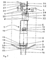
- the sanitary device according to the invention in Fig. 1 has a drain valve 1 with an actuator 2.
- the drain valve 1 is arranged in the bottom region of the Spippokastengeophuses 3.
- the actuating device 2 is attached to a traverse 4 in the upper region of the Spülkastengephaseuses 3.
- the drain valve 1 consists of an upper housing part 5, a lower housing part 6, a sealing element 7 and an overflow pipe 8.
- the sealing element 7 is arranged in the lower part of the Spippokastengepuruses 3 and connected via webs 9 with the lower housing part 6.
- the lower housing part 6 and the upper housing part 5 are connected to one another via a latching element 10.
- the locking element 10 is made from a latching lug 11 on the lower housing part 6 and a flap 12 formed in the upper housing part 5, which has a latching opening 13 for engagement with the latching lug 11.
- the overflow pipe 8 is movably arranged in the upper housing part 5 and the lower housing part 6, wherein it has an area lying above the upper housing part 5 and extends through the upper housing part 5 and the lower housing part 6 to the sealing element 7.
- the sealing element 7 has at its directed to the Spippokastengephaseuse 3 part of a cistern seal 14, which seals the cistern together with the stop shoulder 15 in the connection piece 16 of the Spülkastengephases 3 downwards.
- the cistern housing 3 is located in the lower area on a Spülkastenhalterung 17, which has a recess in the region of the connecting piece 16.
- the standing with the sealing member 7 in communication lower part of the overflow pipe 8 has an outer guide ring 18 which is guided between the webs 9, wherein the lateral clearance of the lower part of the overflow pipe 8 is limited by the small clearance to the guide ring 18.
- the drain valve 1 has between the webs 9 openings 19 for the passage of the rinse water, which are bounded above by the lower housing part 6 and downwards from the sealing element 7. Between the overflow pipe 8 and the sealing element 7, an overflow pipe seal 20 is provided, which prevents a drainage of the rinsing water through the openings 19 and the sealing element 7 in the connecting piece 16 in the closed state.
- the actuating device 2 consists of a servomotor 21, which can be addressed via a connection line 22 and a lever arm 23 arranged on the servomotor, which transmits the movement of the servomotor 21 to a latching rod 24.
- the locking rod 24 has a round in cross-section shape with arranged at regular intervals over the length of the locking rod 24 cross-sectional constrictions.
- the locking rod 24 is connected via the locking element 25 with the upper portion of the lever arm 23.
- the latching region of the locking element 25 is designed as a cylinder slotted on both sides, wherein the slotted areas engage in the cross-sectional constrictions of the locking rod 24.
- the servomotor 21 is disposed on a mounting base 26 which is mounted on a mounting bar 4, which is connected to the Spülkastengeophuse 3 or a cover of the Spülkastengeophuses.
- a lateral actuating pin 28 is arranged, which engages in a connecting element 29 which is arranged at the upper end of the overflow pipe 8.
- the lower end of the locking rod 24 with the side Actuating pin 28 is guided in a protective sleeve 30, which has a slot to the overflow pipe 8, through which the lateral actuating pin 28 can engage in the connecting element 29.
- the servomotor 21 may be connected via the connecting line 22 to an optional program control not shown in the figures.
- the program control can be arranged directly on the servo motor 21 or at any position in the cistern or outside the cistern.
- a control of the program control can be done by an operating unit not shown in detail, which optionally transmits the control signals by a radio device to the program control.
- Fig. 2 In addition to the overflow pipe seal 20 and the cooperating with this seal sealing surface 31 can be seen at the bottom of the overflow pipe 8.
- the lower end of the overflow pipe 8 below the sealing surface 31 is matched in its shape to the inner contour of the sealing element 7. This area closes off towards the sealing element 7 with a further seal 32, which prevents the flushing water from flowing out of the flushing cistern when the drain valve is closed as a further seal.
- the cistern seal 14 arranged on the sealing element 7 of the drain valve 1 seals the cistern to the connecting piece 16, so that the flushing water can only reach the connecting piece 16 via the openings 19 and the sealing element 7 provided with an opening in the interior.
- the overflow pipe seal 20 closes on the sealing element 7 in conjunction with the sealing surface 31 on the overflow pipe 8 and the seal 32 of the overflow pipe 8, the passage in the sealing element 7.
- the flushing water can not get into the connecting piece 16 in this closed end state.
- the cistern is filled with rinse water and the waterline 33 is at a high level just below the top of the overflow tube 8.
- the servo motor 21 moves the locking rod 24 and connected to the locking rod overflow pipe 8 down.
- the overflow pipe seal 20 and the seal 32 on the overflow pipe 8 are pressed onto their sealing surfaces and close the passage in the sealing element 7.
- the inflow of rinse water to the connecting piece 16 is thereby interrupted.
- the water level 33 rises again in the cistern.
Landscapes
- Health & Medical Sciences (AREA)
- Public Health (AREA)
- Engineering & Computer Science (AREA)
- Life Sciences & Earth Sciences (AREA)
- Hydrology & Water Resources (AREA)
- Water Supply & Treatment (AREA)
- Epidemiology (AREA)
- Aviation & Aerospace Engineering (AREA)
- Electrically Driven Valve-Operating Means (AREA)
- Sanitary Device For Flush Toilet (AREA)
- Toys (AREA)
- Multiple-Way Valves (AREA)
Description
- Die Erfindung bezieht sich auf eine Sanitärvorrichtung mit einem in einem WC-Spülkasten angeordneten Ablaufventil und einer elektrisch betätigten Betätigungsvorrichtung zum Öffnen des Ablaufventils.
- Einfache Ablaufventile für Spülkästen bestehen aus einem Ventilverschlusselement, das mit einem im Boden des Spülkastens angeordneten Ventilsitz zusammenwirkt. Bei diesen einfachen Ablaufventilen erfolgt das Öffnen durch eine direkt am Verschlusselement angreifende Betätigungskraft, die mittels einer Zugstange oder Kette auf das Verschlusselement übertragen wird.
- Bei den derzeit gebräuchlichsten Ablaufventilen ist das Ventilverschlusselement als Überlaufrohr ausgebildet, wobei der Ventilsitz an der Ablauföffnung im Boden des Spülkastens mit einem Ringflansch am Überlaufrohr zusammenwirkt, um das Ablaufventil zu schließen. Zum Öffnen des Ablaufventils wird das gesamte Überlaufrohr angehoben. Sobald das Ablaufventil eine bestimmte Öffnungsstellung überschreitet, bewirkt der statische Druck der Wassersäule ein selbsttätiges, vollständiges Öffnen des Ventils, wobei das Überlaufrohr während des Spülvorgangs von einem Schwimmer in der geöffneten Stellung gehalten wird. Zum Ende des Spülvorgangs sinkt das Überlaufrohr zusammen mit dem Wasserstand im Spülkasten bis der Ringflansch am Überlaufrohr auf dem Ventilsitz aufliegt und das Ablaufventil absperrt. Neben der gebräuchlichen mechanischen Betätigung des Überlaufrohrs beim Öffnen des Ablaufventils sind für diese Art von Ablaufventilen auch Betätigungseinrichtungen mit Magnetventilen bekannt.
- Des Weiteren sind aus der
US 4.392.260 undUS 5.003.643 sanitäre Spülvorrichtungen mit einfachen Ventilverschlusselementen bekannt, die zur Auslösung der Spülvorgänge mit einem Elektromotor ausgestattet sind. Nach dem Auslösen des Spülvorgangs wird bei diesen Vorrichtungen die Drehbewegung des Elektromotors über ein Getriebe und einen Hebelarm, an dem die mit dem Ventilverschlusselement verbundene Kette angreift, in die benötigte lineare Betätigungskraft zum Öffnen des Ablaufventils umgewandelt. Während des Spülvorgangs ist die Drehbewegung des Motors gestoppt. Nach dem Ende des Spülvorgangs dreht der Elektromotor in die entgegengesetzte gengesetzte Richtung und das Ventilverschlusselement fällt durch die Schwerkraft in die geschlossene Endstellung zurück. - Die bekannten Ablaufventile beruhen, auch wenn sie mit einer elektrisch betätigten Betätigungsvorrichtung zum Öffnen ausgestattet sind, auf relativ alten technischen Konzepten unter Verwendung hydro-mechanischer Effekte und der Schwerkraft.
- Weiterhin ist aus der
FR-A-2 770 547 - Aus der
FR-A-2 740 793 - Weiterhin ist aus der
GB-A-2 277 941 - Weiterhin zeigt die
JP 2002 315693 A - Der Erfindung liegt die Aufgabe zugrunde, eine Sanitärvorrichtung der eingangs genannten Art bereitzustellen, die über die bisherigen technischen Konzepte hinausgeht.
- Diese Aufgabe wird erfindungsgemäß dadurch gelöst, dass die Betätigungsvorrichtung einen Servomotor umfasst, und der Servomotor zum Öffnen und Schließen des Ablaufventils mit dem Ablaufventil mittels einer Zwangskopplung verbunden ist.
- Durch die Einbindung eines Servomotors in die Betätigungsvorrichtung können im Vergleich zu herkömmlichen Elektromotoren schnelle Öffnungs- und Schließbewegungen realisiert werden. Weiter ermöglicht die erfindungsgemäße Ausgestaltung einer Sanitärvorrichtung, dass das Ablaufventil zu jeder Zeit ganz genau ansteuerbar ist, und dass neben einem aktiven Öffnen auch ein aktives Schließen des Ablaufventils möglich ist. Eine solche aktive sanitäre Spülvorrichtung ist auch gut für die Integration in computergestützte Haustechnikkonzepte geeignet.
- Eine weitere Ausbildung der Erfindung sieht vor, dass das Ablaufventil ein Übedaufrohr umfasst und der Servomotor mit dem Überlaufrohr des Ablaufventils verbunden ist. Hierdurch wird die benötigte Betätigungskraft zum Öffnen des mit dem Überlaufrohr verbundenen Ventilverschlusselements reduziert, da der statische Druck der Wassersäule das Öffnen des Ablaufventils unterstützt. Damit die Betätigungsvorrichtung an verschiedene Einbaugegebenheiten anpassbar ist, kann der Servomotor relativ zum Überlaufrohr lagerveränderlich anbringbar sein.
- Günstigerweise kann die Zwangskopplung zum Ausgleich der lagerveränderlichen Anbringung des Servomotors mindestens mit einer ersten Verbindungsstelle am Servomotor und mindestens einer weiteren Verbindungsstelle am Überlaufrohr befestigt sein. Hierdurch ist eine Einstellung der Zwangskopplung auf unterschiedliche Konstruktionen von WC-Spülkästen und unterschiedlichen Positionen des Servomotors auf einer Montagevorrichtung oberhalb des maximal möglichen Wasserspiegels einstellbar. Dadurch wird trotz unterschiedlicher Konstruktionen und Positionen eine leichtgängige Betätigung des Ablaufventils sichergestellt.
- Eine vorteilhafte Ausführungsform sieht vor, dass die Zwangskopplung einen in mehreren Lagen arretierbaren Rastmechanismus aufweist. Dieser Rastmechanismus ermöglicht die Anpassung der Zwangskopplung auf die individuelle Montagesituation und Montageabweichungen in den einzelnen WC-Spülkästen. Auch die Wirkung des Servomotors auf das Ablaufventil ist durch diesen in mehreren Lagen arretierbaren Rastmechanismus veränderbar. Solche Rastmechanismen können in Form von Zahnstangen oder aneinander gereihten Rastelementen bzw. Rastnasen realisiert werden, die in vielen Positionen arretierbar sind.
- Zur einfachen Anbindung der Zwangskopplung an das Überlaufrohr kann an der mindestens einen weiteren Verbindungsstelle zumindestens ein Verbindungselement vorgesehen sein, das das Überlaufrohr an seinem Außenumfang umgreift. Dabei muss das Verbindungselement den Außenumfang nicht vollständig umschließen, sondern nur soweit umfassen, dass eine sichere Verbindung zum Überlaufrohr entsteht.
- Eine zweckmäßige Ausbildung der erfindungsgemäßen Sanitärvorrichtung sieht vor, dass über den Servomotor Zwischenstellungen zwischen einer geöffneten Endstellung und einer geschlossenen Endstellung des Ablaufventils anfahrbar sind. Durch solche Zwischenstellungen können bei einem Spülvorgang an einen geringeren Spülbedarf angepasste geringere Spülmengen realisiert werden, z.B. bei lediglichem Flüssigkeitseintrag in das WC-Becken oder um das Toilettenbecken zu befeuchten. Auch lassen sich durch Zwischenstellungen des Ablaufventils ein geringerer Volumenstrom des Spülwassers einstellen und dadurch eine Verlängerung bzw. Anpassung des Spülvorgangs an die jeweiligen Gegebenheiten verwirklichen.
- Vorteilhafterweise kann der Servomotor mit einer programmierbaren und speichernden Programmsteuerung verbunden sein, und durch die Programmsteuerung das Öffnen und Schließen des Ablaufventils, sowie die Stellung des Ablaufventils und die Verweildauer in dieser Stellung ansteuerbar sein. Hierdurch lassen sich auf den Einzelfall abgestimmte Spülvorgänge mit unterschiedlichen Volumenströmen und Spülzeiträumen verwirklichen. Auch können, um eine Geruchsbildung in wenig benutzten Toiletten zu vermeiden, zeitabhängige Zwischenspülungen programmiert und ausgeführt werden. Die programmierbare Programmsteuerung ermöglicht auch besondere Spülabläufe, die trotz eines geringeren Wassereinsatzes einen besseren Spülerfolg ermöglichen, wie Stotter- oder Intervallspülungen.
- Um mit der Sanitärvorrichtung auch eine Reinigung des Toilettenbeckens zu ermöglichen, kann die Sanitärvorrichtung eine, insbesondere im WC-Spülkasten angeordnete, Reinigungsmitteleinheit umfassen, über die dem WC-Spülkasten und/oder dem Ablaufventil ein Reinigungsmittel zuführbar sein kann.
- Um eine einstellbare Dosierung und Zuführung des Reinigungsmittels zu ermöglichen, kann die Programmsteuerung das Zuführen des Reinigungsmittels steuern. Dadurch wird auch eine weitere Steuereinheit für die Reinigungsmittelzuführung überflüssig.
- Eine Variante der erfindungsgemäßen Sanitärvorrichtung sieht vor, dass die Programmsteuerung in einem definierten Spülablauf das Öffnen und Schließen, die Stellung und Verweildauer des Ablaufventils sowie das Zuführen des Reinigungsmittels zueinander abgestimmt steuert. Der auf diese Weise auf die Anforderungen des Anwendungsfalls und des gewählten Spülvorgangs angepasste Spülablauf ermöglicht durch die abgestimmte Zuführung des Reinigungsmittels eine gute Reinigungswirkung.
- Eine weitere Ausbildung sieht vor, dass von einer Bedieneinheit des Ablaufventils zumindestens eine weitere Funktion im Sanitärbereich, insbesondere eine Notruffunktion, die Beleuchtung oder eine Belüftung, gesteuert ist. Das Zusammenführen unterschiedlicher Funktionen aus dem Sanitärbereich erhöht den Komfort für den Benutzer und bietet insbesondere Behinderten oder alten Menschen eine Erleichterung. Neben einer in vielen Anwendungsfällen wichtigen Notruftaste kann die Bedieneinheit Tasten zur Betätigung des Lichts, eines Lüfters, einer Geruchsabsaugung, eines lonisators sowie weiterer Funktionen umfassen.
- Günstigerweise kann die Bedieneinheit die Steuersignale an die Betätigungseinrichtung durch eine Funkeinrichtung übertragen. Dies ermöglicht eine freie Positionierung der Bedieneinheit unabhängig von der Anordnung des WC-Spülkastens. Des Weiteren ist durch die Funkübertragung der Steuersignale keine Verkabelung notwendig, wodurch das Nachrüsten bestehender Sanitäreinrichtungen erheblich vereinfacht wird.
- Zusätzlich bezieht sich die Erfindung auf die Verwendung eines Servomotors zur Betätigung einer Betätigungseinrichtung zum Öffnen und Schließen eines Ablaufventils einer elektrisch betätigten Sanitärspülung, wobei der Servomotor mit dem Ablaufventil durch eine Zwangskopplung verbunden ist. Die Verwendung zeichnet sich dadurch aus, dass für die elektrisch betätigte Sanitärspülung ein Servomotor eingesetzt ist, durch den über die Zwangskopplung das Ablaufventil zu jedem Zeitpunkt genau angesteuert werden kann. Auch ermöglicht die Zwangskopplung des Ablaufventils zum Servomotor schnelle, aktive Öffnungs- und Schließbewegungen.
- Im Folgenden werden Ausführungsbeispiele der vorliegenden Erfindung anhand einer Zeichnung näher erläutert. Es zeigen:
- Fig. 1
- einen Teil eines gefüllten WC-Spülkastens im Längsschnitt mit einem geschlossenen Ablaufventil, und
- Fig. 2
- den in
Fig. 1 gezeigten WC-Spülkasten mit geöffnetem Ablaufventil und erheblich abgesenktem Wasserspiegel. - Die erfindungsgemäße Sanitärvorrichtung in
Fig. 1 weist ein Ablaufventil 1 mit einer Betätigungsvorrichtung 2 auf. Das Ablaufventil 1 ist im Bodenbereich des Spülkastengehäuses 3 angeordnet. Die Betätigungsvorrichtung 2 ist im oberen Bereich des Spülkastengehäuses 3 an einer Traverse 4 befestigt. - Das Ablaufventil 1 besteht aus einem Gehäuseoberteil 5, einem Gehäuseunterteil 6, einem Dichtungselement 7 und einem Überlaufrohr 8. Dabei ist das Dichtungselement 7 in dem Unterteil des Spülkastengehäuses 3 angeordnet und über Stege 9 mit dem Gehäuseunterteil 6 verbunden. Das Gehäuseunterteil 6 und das Gehäuseoberteil 5 sind über ein Rastelement 10 miteinander verbunden. Das Rastelement 10 besteht aus einer Rastnase 11 auf dem Gehäuseunterteil 6 sowie einer im Gehäuseoberteil 5 ausgebildeten Lasche 12, die eine Rastöffnung 13 zum Eingriff für die Rastnase 11 aufweist. Das Überlaufrohr 8 ist beweglich in dem Gehäuseoberteil 5 und dem Gehäuseunterteil 6 angeordnet, wobei es einen oberhalb des Gehäuseoberteils 5 liegenden Bereich aufweist und sich durch das Gehäuseoberteil 5 und das Gehäuseunterteil 6 bis zum Dichtungselement 7 erstreckt. Das Dichtungselement 7 weist an seinem zum Spülkastengehäuse 3 gerichteten Teil eine Spülkastendichtung 14 auf, die zusammen mit der Anschlagschulter 15 im Anschlussstutzenbereich 16 des Spülkastengehäuses 3 den Spülkasten nach unten hin abdichtet. Das Spülkastengehäuse 3 liegt im unteren Bereich auf einer Spülkastenhalterung 17 auf, die im Bereich des Anschlussstutzen 16 eine Aussparung aufweist. Der mit dem Dichtungselement 7 in Verbindung stehende untere Teil des Überlaufrohrs 8 weist einen äußeren Führungsring 18 auf, der zwischen den Stegen 9 geführt ist, wobei durch das geringe Spiel zum Führungsring 18 die seitliche Bewegungsfreiheit des unteren Teils des Überlaufrohrs 8 einschränkt ist. Das Ablaufventil 1 weist zwischen den Stegen 9 Öffnungen 19 zum Durchtritt des Spülwassers auf, die nach oben von dem Gehäuseunterteil 6 und nach unten von dem Dichtungselement 7 begrenzt sind. Zwischen den Überlaufrohr 8 und dem Dichtungselement 7 ist eine Überlaufrohrdichtung 20 vorgesehen, die im geschlossenen Zustand ein Ablaufen des Spülwassers durch die Öffnungen 19 und das Dichtungselement 7 in den Anschlussstutzen 16 verhindert.
- Die Betätigungsvorrichtung 2 besteht aus einem Servomotor 21, der über eine Anschlussleitung 22 ansprechbar ist und einem an den Servomotor angeordneten Hebelarm 23, der die Bewegung des Servomotors 21 auf eine Raststange 24 überträgt. Die Raststange 24 weist eine im Querschnitt runde Form auf mit in regelmäßigen Abständen über die Länge der Raststange 24 angeordneten Querschnittsverengungen. Die Raststange 24 ist über das Feststellelement 25 mit dem oberen Bereich des Hebelarms 23 verbunden. Dabei ist der Rastbereich des Feststellelement 25 als beidseitig geschlitzter Zylinder ausgebildet, wobei die geschlitzten Bereiche in die Querschnittsverengungen der Raststange 24 eingreifen. Der Servomotor 21 ist auf einem Montagesockel 26 angeordnet, der auf einer Befestigungstraverse 4 befestigt ist, die mit dem Spülkastengehäuse 3 oder einer Abdeckung des Spülkastengehäuses verbunden ist. Am unteren Ende der Raststage 24 ist ein seitlicher Betätigungsstift 28 angeordnet, der in ein Verbindungselement 29 eingreift, das am oberen Ende des Überlaufrohrs 8 angeordnet ist. Das untere Ende der Raststange 24 mit dem seitlichen Betätigungsstift 28 ist in einer Schutzhülse 30 geführt, die zum Überlaufrohr 8 hin einen Schlitz aufweist, durch den der seitliche Betätigungsstift 28 in das Verbindungselement 29 eingreifen kann.
- Der Servomotor 21 kann über die Anschlussleitung 22 mit einer in den Figuren nicht gezeigten, optionalen Programmsteuerung verbunden sein. Die Programmsteuerung kann dabei direkt am Servomotor 21 oder an einer beliebigen Position im Spülkasten oder auch außerhalb des Spülkastens angeordnet sein. Eine Ansteuerung der Programmsteuerung kann durch eine nicht im Einzelnen dargestellten Bedieneinheit erfolgen, die optional die Steuersignale durch eine Funkeinrichtung an die Programmsteuerung überträgt.
- In
Fig. 2 ist neben der Überlaufrohrdichtung 20 auch die mit dieser Dichtung zusammenwirkende Dichtfläche 31 am unteren Ende des Überlaufrohrs 8 zu sehen. Das untere Ende des Überlaufrohrs 8 unterhalb der Dichtfläche 31 ist in seiner Form auf die Innenkontur des Dichtungselements 7 abgestimmt. Dieser Bereich schließt zum Dichtungselement 7 hin mit einer weiteren Dichtung 32 ab, die bei einem geschlossenen Ablaufventil als weitere Dichtung ein Abfließen des Spülwassers aus dem Spülkasten verhindert. - Die an dem Dichtungselement 7 des Ablaufventils 1 angeordnete Spülkastendichtung 14 dichtet den Spülkasten zum Anschlussstutzen 16 hin ab, so dass das Spülwasser nur über die Öffnungen 19 und das im Inneren mit einem Durchlass versehene Dichtungselement 7 in den Anschlussstutzen 16 gelangen kann. Im geschlossenen Zustand, wie in
Fig. 1 gezeigt, verschließt die Überlaufrohrdichtung 20 am Dichtungselement 7 in Verbindung mit der Dichtfläche 31 am Überlaufrohr 8 sowie die Dichtung 32 des Überlaufrohrs 8 den Durchlass im Dichtungselement 7. Das Spülwasser kann in diesem geschlossenen Endzustand nicht in den Anschlussstutzen 16 gelangen. Der Spülkasten ist mit Spülwasser gefüllt und die Wasserlinie 33 befindet sich auf einem hohen Niveau kurz unterhalb des oberen Endes des Überlaufrohrs 8. - Bei einer Betätigung des Servomotors 21 wird die Drehbewegung an der Welle des Servomotors 21 durch den Hebelarm 23 in eine lineare Bewegung an der Raststange 24 umgewandelt. Die Raststange 24 wird durch die Bewegung des Hebelarms 23 nach oben bewegt. Zusammen mit der Raststange 24 bewegt sich auch der mit ihr verbundene seitliche Betätigungsstift 28 und über den seitlichen Betätigungsstift 28 durch den Eingriff in das Verbindungselement 29 auch das mit diesem verbundene Überlaufrohr 8. Durch die Bewegung des Überlaufrohrs 8 nach oben werden sowohl die Überlaufrohrdichtung 20 als auch die Dichtung 32 am Überlaufrohr 8 von ihren Dichtflächen gelöst. Das Spülwasser fließt durch die Öffnungen 19 vorbei an den von den geöffneten Dichtungen 20, 32 durch den Durchlass im Dichtungselement 7 in den Anschlussstutzen 16 und von dort aus weiter in das Toilettenbecken. Der Wasserspiegel 33 im Spülkasten sinkt.
- Beim Schließen des Ablaufventils 1 bewegt der Servomotor 21 die Raststange 24 und das mit der Raststange verbundene Überlaufrohr 8 nach unten. Die Überlaufrohrdichtung 20 und die Dichtung 32 am Überlaufrohr 8 werden auf ihre Dichtflächen gedrückt und verschließen den Durchlass im Dichtungselement 7. Der Zulauf von Spülwasser zum Anschlussstutzen 16 wird dadurch unterbrochen. Durch das Einbringen von neuem Spülwasser über das Zulaufventil steigt der Wasserspiegel 33 im Spülkasten wieder an.
Claims (12)
- Sanitärvorrichtung- mit einem in einem WC-Spülkasten auzuordnenden Ablaufventil (1) und- einer elektrisch betätigten Betätigungsvorrichtung (2) zum Öffnen des Ablaufventils (1),- wobei die Betätigungsvorrichtung (2) einen Motor (21) umfasst und- der Motor (21) zum Öffnen und Schließen des Ablaufventils (1) mit dem Ablaufventil (1) mittels einer Zwangskopplung verbunden ist, dadurch gekennzeichnet, daß der Motor (21) ein Servomotor ist, mit dem Zwischenstellungen zwischen einer geöffneten Endstellung und einer geschlossenen Endstellung des Ablaufventils (1) anfahrbar sind.
- Sanitärvorrichtung nach Anspruch 1, dadurch gekennzeichnet, dass das Ablaufventil (1) ein Überlaufrohr (8) umfasst und der Servomotor (21) mit dem Überlaufrohr (8) des Ablaufventils (1) verbunden ist.
- Sanitärvorrichtung nach Anspruch 2, dadurch gekennzeichnet, dass der Servomotor (21) relativ zum Überlaufrohr (8) lageveränderlich anbringbar ist.
- Sanitärvorrichtung nach Anspruch 3, dadurch gekennzeichnet, dass die Zwangskopplung zum Ausgleich der lageveränderlichen Anbringung des Servomotors (21) mindestens an einer ersten Verbindungsstelle am Servomotor (21) und an mindestens einer weiteren Verbindungsstelle am Überlaufrohr (8) befestigt ist.
- Sanitärvorrichtung nach einem der Ansprüche 1 bis 4, dadurch gekennzeichnet, dass die Zwangskopplung einen in mehreren Lagen arretierbaren Rastmechanismus (25) aufweist.
- Sanitärvorrichtung nach einem der Ansprüche 4 oder 5, dadurch gekennzeichnet, dass an der mindestens einen weiteren Verbindungsstelle zumindest ein Verbindungselement (29) vorgesehen ist, dass das Überlaufrohr (8) an seinem Außenumfang umgreift.
- Sanitärvorrichtung nach einem der Ansprüche 1 bis 6, dadurch gekennzeichnet, dass der Servomotor (21) mit einer programmierbaren und speichernden Programmsteuerung verbunden ist, und dass durch die Programmsteuerung das Öffnen und Schließen des Ablaufventils (1), sowie die Stellung des Ablaufventils (1) und die Verweildauer in dieser Stellung ansteuerbar sind.
- Sanitärvorrichtung nach einem der Ansprüche 1 bis 7, dadurch gekennzeichnet, dass die Sanitärvorrichtung eine, insbesondere im WC-Spülkasten angeordnete, Reinigungsmitteleinheit umfasst, über die dem WC-Spülkasten und/oder dem Ablaufventil (1) ein Reinigungsmittel zuführbar ist.
- Sanitärvorrichtung nach Anspruch 8, dadurch gekennzeichnet, dass die Programmsteuerung das Zuführen des Reinigungsmittels steuert.
- Sanitärvorrichtung nach Anspruch 9, dadurch gekennzeichnet, dass die Programmsteuerung in einem definierten Spülablauf das Öffnen und Schließen, die Stellung und Verweildauer des Ablaufventils (1), sowie das Zuführen des Reinigungsmittels zueinander abgestimmt steuert.
- Sanitärvorrichtung nach einem der Ansprüche 1 bis 10, dadurch gekennzeichnet, dass von einer Bedieneinheit des Ablaufventils (1) zumindest eine weitere Funktion im Sanitärbereich, insbesondere eine Notruffunktion, die Beleuchtung oder eine Belüftung gesteuert ist.
- Sanitärvorrichtung nach Anspruch 11, dadurch gekennzeichnet, dass die Bedieneinheit die Steuersignale an die Betätigungsvorrichtung durch eine Funkeinrichtung überträgt.
Priority Applications (1)
| Application Number | Priority Date | Filing Date | Title |
|---|---|---|---|
| PL04014560T PL1493873T3 (pl) | 2003-07-04 | 2004-06-22 | Zawór odpływowy z serwosilnikiem |
Applications Claiming Priority (2)
| Application Number | Priority Date | Filing Date | Title |
|---|---|---|---|
| DE10330324A DE10330324A1 (de) | 2003-07-04 | 2003-07-04 | Ablaufventil mit Servomotor |
| DE10330324 | 2003-07-04 |
Publications (3)
| Publication Number | Publication Date |
|---|---|
| EP1493873A2 EP1493873A2 (de) | 2005-01-05 |
| EP1493873A3 EP1493873A3 (de) | 2006-04-26 |
| EP1493873B1 true EP1493873B1 (de) | 2008-08-06 |
Family
ID=33426873
Family Applications (1)
| Application Number | Title | Priority Date | Filing Date |
|---|---|---|---|
| EP04014560A Expired - Lifetime EP1493873B1 (de) | 2003-07-04 | 2004-06-22 | Ablaufventil mit Servomotor |
Country Status (5)
| Country | Link |
|---|---|
| EP (1) | EP1493873B1 (de) |
| AT (1) | ATE403785T1 (de) |
| DE (2) | DE10330324A1 (de) |
| DK (1) | DK1493873T3 (de) |
| PL (1) | PL1493873T3 (de) |
Families Citing this family (2)
| Publication number | Priority date | Publication date | Assignee | Title |
|---|---|---|---|---|
| CN102605844B (zh) * | 2012-04-11 | 2013-09-18 | 厦门瑞尔特卫浴科技股份有限公司 | 一种双档排水阀线控机构 |
| EP2660399B1 (de) | 2012-05-03 | 2014-08-20 | Geberit International AG | Betätigungsvorrichtung für ein Auslaufventil einer Spülvorrichtung |
Family Cites Families (15)
| Publication number | Priority date | Publication date | Assignee | Title |
|---|---|---|---|---|
| US4392260A (en) | 1982-07-06 | 1983-07-12 | Bensen Court M | Flushing apparatus with selective quantity control |
| US5003643A (en) * | 1989-11-14 | 1991-04-02 | Wilson Chung | Flush controller for a toilet bowl |
| US5036553A (en) * | 1990-06-26 | 1991-08-06 | Sanderson Dilworth D | Fully automatic toilet system |
| GB9310039D0 (en) * | 1993-05-15 | 1993-06-30 | Smiths Industries Plc | Water management and treatment systems |
| GB2302623A (en) * | 1995-06-24 | 1997-01-22 | Lukes Engineering Co Ltd | Electric motor drive device for operating a lever |
| IT1280896B1 (it) * | 1995-08-04 | 1998-02-11 | Plastic Investment Holding S A | Dispositivo pneumatico per l'azionamento di una valvola di scarico di una cassetta di risciacquo per wc |
| FR2740793B1 (fr) * | 1995-11-03 | 1998-01-30 | Wirquin Plastiques Sa | Dispositif de commande de vidage d'appareils sanitaires |
| DE19631078A1 (de) * | 1996-08-01 | 1998-02-05 | Siegfried Verl | Verfahren zur Reinigung von Toilettenbecken |
| FR2770547B1 (fr) * | 1997-11-03 | 2000-02-11 | Wirquin Plastiques Sa | Dispositif de commande electrique de chasse d'eau sanitaire permettant de deverser des quantites d'eau variables |
| NO314638B1 (no) * | 1998-12-17 | 2003-04-22 | Ido Bathroom Ltd | Anordning ved beröringsfri klosettspyler |
| DE20104033U1 (de) * | 2000-05-18 | 2001-06-21 | Geberit Technik Ag, Jona | Spülkasten für eine Klosettanlage |
| JP2002315693A (ja) * | 2001-04-20 | 2002-10-29 | Toto Ltd | トイレ設備 |
| DE20117432U1 (de) * | 2001-10-24 | 2002-01-24 | Georg Fischer Schwab GmbH & Co. KG, 72793 Pfullingen | Zweimengenspülvorrichtung |
| FR2835550B1 (fr) * | 2002-02-06 | 2006-12-01 | Wirquin Plastiques Sa | Dispositif de commande motorise pour mecanisme de chasse d'eau |
| DE10222193A1 (de) * | 2002-05-18 | 2003-11-27 | Thomas Wartmann | Elektronische Wasserspülung |
-
2003
- 2003-07-04 DE DE10330324A patent/DE10330324A1/de not_active Withdrawn
-
2004
- 2004-06-22 AT AT04014560T patent/ATE403785T1/de not_active IP Right Cessation
- 2004-06-22 DK DK04014560T patent/DK1493873T3/da active
- 2004-06-22 PL PL04014560T patent/PL1493873T3/pl unknown
- 2004-06-22 EP EP04014560A patent/EP1493873B1/de not_active Expired - Lifetime
- 2004-06-22 DE DE502004007761T patent/DE502004007761D1/de not_active Expired - Lifetime
Also Published As
| Publication number | Publication date |
|---|---|
| PL1493873T3 (pl) | 2009-01-30 |
| EP1493873A2 (de) | 2005-01-05 |
| ATE403785T1 (de) | 2008-08-15 |
| DE502004007761D1 (de) | 2008-09-18 |
| DE10330324A1 (de) | 2005-01-20 |
| EP1493873A3 (de) | 2006-04-26 |
| DK1493873T3 (da) | 2008-12-01 |
Similar Documents
| Publication | Publication Date | Title |
|---|---|---|
| EP2986787B1 (de) | Wc mit intimdusche, die im spülwasserverteiler integriert ist | |
| EP0915210B1 (de) | Ablaufventil für Spülkästen | |
| DE3153688C2 (de) | ||
| EP1703027B1 (de) | Vorrichtung zur Betätigung des Ablaufventils von Sanitärartikeln und insbesondere einer Badewanne | |
| DE4241023C2 (de) | Vorrichtung zur Verhinderung oder Verminderung der durch Waschbecken, Spülbecken, Badewannen o. dgl. verursachten Keime | |
| EP3728747B1 (de) | Ventil | |
| WO2018104413A1 (de) | Druckwasserventil | |
| EP2322729B1 (de) | Ab- und Überlaufgarnitur, insbesondere für Badewannen | |
| DE1675528C3 (de) | Umschalter für einen Wasserhahn an Badewannen | |
| EP1813732B1 (de) | Drehrosette zur Betätigung eines Ablaufventils einer Ab- und Überlaufgarnitur einer Badewanne | |
| DE2010111A1 (de) | Wasserklosett mit Entlüftungs- und Spülvorrichtung | |
| EP1493873A2 (de) | Ablaufventil mit Servomotor | |
| DE10002308C2 (de) | WC-Spülkasten | |
| DE3841911C2 (de) | Sanitärarmatur | |
| CH621378A5 (en) | Upwardly directed shower device for WCs | |
| DE29900260U1 (de) | Spüleinrichtung an einer eine Klosettschüssel aufweisenden Klosettanlage | |
| EP1842972A1 (de) | Sanitärarmatur mit versenkbarem Auslauf | |
| EP4187028B1 (de) | Filtereinrichtung für einen spülkasten und spülkasten für eine sanitäreinrichtung | |
| DE10300931A1 (de) | Vorrichtung zum Betätigen der Ablaufglocke eines WC-Spülkastens | |
| EP1388617B1 (de) | Ablaufgarnitur | |
| DE102007017377B4 (de) | Hydrant-Entleerungssystem | |
| DE4116320A1 (de) | Wasserkasten - fuell,- und ablassventil | |
| DE10248016B3 (de) | Stellorgan sowie dieses umfassender Ablöschkasten und Verfahren zur Regelung des Füllstands eines Flüssigkeitssammelbehälters | |
| EP0520267A1 (de) | Verfahren zum Steuern einer Hubeinrichtung und Hubeinrichtung für bewegungsbehinderte Menschen | |
| EP0451096B1 (de) | Unterdusche für ein Wasserklosett |
Legal Events
| Date | Code | Title | Description |
|---|---|---|---|
| PUAI | Public reference made under article 153(3) epc to a published international application that has entered the european phase |
Free format text: ORIGINAL CODE: 0009012 |
|
| AK | Designated contracting states |
Kind code of ref document: A2 Designated state(s): AT BE BG CH CY CZ DE DK EE ES FI FR GB GR HU IE IT LI LU MC NL PL PT RO SE SI SK TR |
|
| AX | Request for extension of the european patent |
Extension state: AL HR LT LV MK |
|
| PUAL | Search report despatched |
Free format text: ORIGINAL CODE: 0009013 |
|
| AK | Designated contracting states |
Kind code of ref document: A3 Designated state(s): AT BE BG CH CY CZ DE DK EE ES FI FR GB GR HU IE IT LI LU MC NL PL PT RO SE SI SK TR |
|
| AX | Request for extension of the european patent |
Extension state: AL HR LT LV MK |
|
| RAP1 | Party data changed (applicant data changed or rights of an application transferred) |
Owner name: GROHE AG |
|
| 17P | Request for examination filed |
Effective date: 20061018 |
|
| 17Q | First examination report despatched |
Effective date: 20061121 |
|
| AKX | Designation fees paid |
Designated state(s): AT BE BG CH CY CZ DE DK EE ES FI FR GB GR HU IE IT LI LU MC NL PL PT RO SE SI SK TR |
|
| GRAP | Despatch of communication of intention to grant a patent |
Free format text: ORIGINAL CODE: EPIDOSNIGR1 |
|
| GRAS | Grant fee paid |
Free format text: ORIGINAL CODE: EPIDOSNIGR3 |
|
| GRAA | (expected) grant |
Free format text: ORIGINAL CODE: 0009210 |
|
| AK | Designated contracting states |
Kind code of ref document: B1 Designated state(s): AT BE BG CH CY CZ DE DK EE ES FI FR GB GR HU IE IT LI LU MC NL PL PT RO SE SI SK TR |
|
| REG | Reference to a national code |
Ref country code: GB Ref legal event code: FG4D Free format text: NOT ENGLISH |
|
| REG | Reference to a national code |
Ref country code: CH Ref legal event code: EP |
|
| REG | Reference to a national code |
Ref country code: IE Ref legal event code: FG4D Free format text: LANGUAGE OF EP DOCUMENT: GERMAN |
|
| REF | Corresponds to: |
Ref document number: 502004007761 Country of ref document: DE Date of ref document: 20080918 Kind code of ref document: P |
|
| REG | Reference to a national code |
Ref country code: CH Ref legal event code: NV Representative=s name: BOVARD AG PATENTANWAELTE |
|
| REG | Reference to a national code |
Ref country code: SE Ref legal event code: TRGR |
|
| REG | Reference to a national code |
Ref country code: DK Ref legal event code: T3 |
|
| PG25 | Lapsed in a contracting state [announced via postgrant information from national office to epo] |
Ref country code: ES Free format text: LAPSE BECAUSE OF FAILURE TO SUBMIT A TRANSLATION OF THE DESCRIPTION OR TO PAY THE FEE WITHIN THE PRESCRIBED TIME-LIMIT Effective date: 20081117 |
|
| REG | Reference to a national code |
Ref country code: PL Ref legal event code: T3 |
|
| PG25 | Lapsed in a contracting state [announced via postgrant information from national office to epo] |
Ref country code: SI Free format text: LAPSE BECAUSE OF FAILURE TO SUBMIT A TRANSLATION OF THE DESCRIPTION OR TO PAY THE FEE WITHIN THE PRESCRIBED TIME-LIMIT Effective date: 20080806 Ref country code: FI Free format text: LAPSE BECAUSE OF FAILURE TO SUBMIT A TRANSLATION OF THE DESCRIPTION OR TO PAY THE FEE WITHIN THE PRESCRIBED TIME-LIMIT Effective date: 20080806 |
|
| REG | Reference to a national code |
Ref country code: IE Ref legal event code: FD4D |
|
| PG25 | Lapsed in a contracting state [announced via postgrant information from national office to epo] |
Ref country code: BG Free format text: LAPSE BECAUSE OF FAILURE TO SUBMIT A TRANSLATION OF THE DESCRIPTION OR TO PAY THE FEE WITHIN THE PRESCRIBED TIME-LIMIT Effective date: 20081106 Ref country code: IE Free format text: LAPSE BECAUSE OF FAILURE TO SUBMIT A TRANSLATION OF THE DESCRIPTION OR TO PAY THE FEE WITHIN THE PRESCRIBED TIME-LIMIT Effective date: 20080806 |
|
| PG25 | Lapsed in a contracting state [announced via postgrant information from national office to epo] |
Ref country code: SK Free format text: LAPSE BECAUSE OF FAILURE TO SUBMIT A TRANSLATION OF THE DESCRIPTION OR TO PAY THE FEE WITHIN THE PRESCRIBED TIME-LIMIT Effective date: 20080806 Ref country code: RO Free format text: LAPSE BECAUSE OF FAILURE TO SUBMIT A TRANSLATION OF THE DESCRIPTION OR TO PAY THE FEE WITHIN THE PRESCRIBED TIME-LIMIT Effective date: 20080806 Ref country code: PT Free format text: LAPSE BECAUSE OF FAILURE TO SUBMIT A TRANSLATION OF THE DESCRIPTION OR TO PAY THE FEE WITHIN THE PRESCRIBED TIME-LIMIT Effective date: 20090106 Ref country code: CZ Free format text: LAPSE BECAUSE OF FAILURE TO SUBMIT A TRANSLATION OF THE DESCRIPTION OR TO PAY THE FEE WITHIN THE PRESCRIBED TIME-LIMIT Effective date: 20080806 |
|
| PLBE | No opposition filed within time limit |
Free format text: ORIGINAL CODE: 0009261 |
|
| STAA | Information on the status of an ep patent application or granted ep patent |
Free format text: STATUS: NO OPPOSITION FILED WITHIN TIME LIMIT |
|
| 26N | No opposition filed |
Effective date: 20090507 |
|
| PG25 | Lapsed in a contracting state [announced via postgrant information from national office to epo] |
Ref country code: EE Free format text: LAPSE BECAUSE OF FAILURE TO SUBMIT A TRANSLATION OF THE DESCRIPTION OR TO PAY THE FEE WITHIN THE PRESCRIBED TIME-LIMIT Effective date: 20080806 |
|
| PG25 | Lapsed in a contracting state [announced via postgrant information from national office to epo] |
Ref country code: IT Free format text: LAPSE BECAUSE OF FAILURE TO SUBMIT A TRANSLATION OF THE DESCRIPTION OR TO PAY THE FEE WITHIN THE PRESCRIBED TIME-LIMIT Effective date: 20080806 |
|
| PGFP | Annual fee paid to national office [announced via postgrant information from national office to epo] |
Ref country code: AT Payment date: 20090615 Year of fee payment: 6 Ref country code: SE Payment date: 20090612 Year of fee payment: 6 |
|
| PGFP | Annual fee paid to national office [announced via postgrant information from national office to epo] |
Ref country code: CH Payment date: 20090617 Year of fee payment: 6 |
|
| PG25 | Lapsed in a contracting state [announced via postgrant information from national office to epo] |
Ref country code: MC Free format text: LAPSE BECAUSE OF NON-PAYMENT OF DUE FEES Effective date: 20090630 |
|
| PG25 | Lapsed in a contracting state [announced via postgrant information from national office to epo] |
Ref country code: GR Free format text: LAPSE BECAUSE OF FAILURE TO SUBMIT A TRANSLATION OF THE DESCRIPTION OR TO PAY THE FEE WITHIN THE PRESCRIBED TIME-LIMIT Effective date: 20081107 |
|
| REG | Reference to a national code |
Ref country code: CH Ref legal event code: PL |
|
| EUG | Se: european patent has lapsed | ||
| PG25 | Lapsed in a contracting state [announced via postgrant information from national office to epo] |
Ref country code: CH Free format text: LAPSE BECAUSE OF NON-PAYMENT OF DUE FEES Effective date: 20100630 Ref country code: LU Free format text: LAPSE BECAUSE OF NON-PAYMENT OF DUE FEES Effective date: 20090622 Ref country code: LI Free format text: LAPSE BECAUSE OF NON-PAYMENT OF DUE FEES Effective date: 20100630 |
|
| PG25 | Lapsed in a contracting state [announced via postgrant information from national office to epo] |
Ref country code: AT Free format text: LAPSE BECAUSE OF NON-PAYMENT OF DUE FEES Effective date: 20100622 |
|
| PG25 | Lapsed in a contracting state [announced via postgrant information from national office to epo] |
Ref country code: HU Free format text: LAPSE BECAUSE OF FAILURE TO SUBMIT A TRANSLATION OF THE DESCRIPTION OR TO PAY THE FEE WITHIN THE PRESCRIBED TIME-LIMIT Effective date: 20090207 |
|
| PG25 | Lapsed in a contracting state [announced via postgrant information from national office to epo] |
Ref country code: TR Free format text: LAPSE BECAUSE OF FAILURE TO SUBMIT A TRANSLATION OF THE DESCRIPTION OR TO PAY THE FEE WITHIN THE PRESCRIBED TIME-LIMIT Effective date: 20080806 |
|
| PG25 | Lapsed in a contracting state [announced via postgrant information from national office to epo] |
Ref country code: CY Free format text: LAPSE BECAUSE OF FAILURE TO SUBMIT A TRANSLATION OF THE DESCRIPTION OR TO PAY THE FEE WITHIN THE PRESCRIBED TIME-LIMIT Effective date: 20080806 |
|
| PGFP | Annual fee paid to national office [announced via postgrant information from national office to epo] |
Ref country code: PL Payment date: 20120524 Year of fee payment: 9 |
|
| PG25 | Lapsed in a contracting state [announced via postgrant information from national office to epo] |
Ref country code: SE Free format text: LAPSE BECAUSE OF NON-PAYMENT OF DUE FEES Effective date: 20100623 |
|
| REG | Reference to a national code |
Ref country code: PL Ref legal event code: LAPE |
|
| PG25 | Lapsed in a contracting state [announced via postgrant information from national office to epo] |
Ref country code: PL Free format text: LAPSE BECAUSE OF NON-PAYMENT OF DUE FEES Effective date: 20130622 |
|
| REG | Reference to a national code |
Ref country code: FR Ref legal event code: PLFP Year of fee payment: 13 |
|
| REG | Reference to a national code |
Ref country code: FR Ref legal event code: PLFP Year of fee payment: 14 |
|
| REG | Reference to a national code |
Ref country code: FR Ref legal event code: PLFP Year of fee payment: 15 |
|
| PGFP | Annual fee paid to national office [announced via postgrant information from national office to epo] |
Ref country code: DK Payment date: 20190621 Year of fee payment: 16 Ref country code: NL Payment date: 20190619 Year of fee payment: 16 Ref country code: DE Payment date: 20190619 Year of fee payment: 16 |
|
| PGFP | Annual fee paid to national office [announced via postgrant information from national office to epo] |
Ref country code: FR Payment date: 20190619 Year of fee payment: 16 Ref country code: BE Payment date: 20190619 Year of fee payment: 16 |
|
| PGFP | Annual fee paid to national office [announced via postgrant information from national office to epo] |
Ref country code: GB Payment date: 20190619 Year of fee payment: 16 |
|
| REG | Reference to a national code |
Ref country code: DE Ref legal event code: R119 Ref document number: 502004007761 Country of ref document: DE |
|
| REG | Reference to a national code |
Ref country code: DK Ref legal event code: EBP Effective date: 20200630 |
|
| REG | Reference to a national code |
Ref country code: NL Ref legal event code: MM Effective date: 20200701 |
|
| GBPC | Gb: european patent ceased through non-payment of renewal fee |
Effective date: 20200622 |
|
| REG | Reference to a national code |
Ref country code: BE Ref legal event code: MM Effective date: 20200630 |
|
| PG25 | Lapsed in a contracting state [announced via postgrant information from national office to epo] |
Ref country code: GB Free format text: LAPSE BECAUSE OF NON-PAYMENT OF DUE FEES Effective date: 20200622 Ref country code: FR Free format text: LAPSE BECAUSE OF NON-PAYMENT OF DUE FEES Effective date: 20200630 Ref country code: NL Free format text: LAPSE BECAUSE OF NON-PAYMENT OF DUE FEES Effective date: 20200701 |
|
| PG25 | Lapsed in a contracting state [announced via postgrant information from national office to epo] |
Ref country code: DE Free format text: LAPSE BECAUSE OF NON-PAYMENT OF DUE FEES Effective date: 20210101 Ref country code: BE Free format text: LAPSE BECAUSE OF NON-PAYMENT OF DUE FEES Effective date: 20200630 |
|
| PG25 | Lapsed in a contracting state [announced via postgrant information from national office to epo] |
Ref country code: DK Free format text: LAPSE BECAUSE OF NON-PAYMENT OF DUE FEES Effective date: 20200630 |