EP1492224A1 - Sensorless controller of ac motor and control method - Google Patents
Sensorless controller of ac motor and control method Download PDFInfo
- Publication number
- EP1492224A1 EP1492224A1 EP20030715432 EP03715432A EP1492224A1 EP 1492224 A1 EP1492224 A1 EP 1492224A1 EP 20030715432 EP20030715432 EP 20030715432 EP 03715432 A EP03715432 A EP 03715432A EP 1492224 A1 EP1492224 A1 EP 1492224A1
- Authority
- EP
- European Patent Office
- Prior art keywords
- magnetic flux
- high frequency
- speed
- motor
- current
- Prior art date
- Legal status (The legal status is an assumption and is not a legal conclusion. Google has not performed a legal analysis and makes no representation as to the accuracy of the status listed.)
- Withdrawn
Links
Images


Classifications
-
- H—ELECTRICITY
- H02—GENERATION; CONVERSION OR DISTRIBUTION OF ELECTRIC POWER
- H02P—CONTROL OR REGULATION OF ELECTRIC MOTORS, ELECTRIC GENERATORS OR DYNAMO-ELECTRIC CONVERTERS; CONTROLLING TRANSFORMERS, REACTORS OR CHOKE COILS
- H02P21/00—Arrangements or methods for the control of electric machines by vector control, e.g. by control of field orientation
- H02P21/14—Estimation or adaptation of machine parameters, e.g. flux, current or voltage
- H02P21/141—Flux estimation
-
- H—ELECTRICITY
- H02—GENERATION; CONVERSION OR DISTRIBUTION OF ELECTRIC POWER
- H02P—CONTROL OR REGULATION OF ELECTRIC MOTORS, ELECTRIC GENERATORS OR DYNAMO-ELECTRIC CONVERTERS; CONTROLLING TRANSFORMERS, REACTORS OR CHOKE COILS
- H02P21/00—Arrangements or methods for the control of electric machines by vector control, e.g. by control of field orientation
- H02P21/04—Arrangements or methods for the control of electric machines by vector control, e.g. by control of field orientation specially adapted for very low speeds
-
- H—ELECTRICITY
- H02—GENERATION; CONVERSION OR DISTRIBUTION OF ELECTRIC POWER
- H02P—CONTROL OR REGULATION OF ELECTRIC MOTORS, ELECTRIC GENERATORS OR DYNAMO-ELECTRIC CONVERTERS; CONTROLLING TRANSFORMERS, REACTORS OR CHOKE COILS
- H02P6/00—Arrangements for controlling synchronous motors or other dynamo-electric motors using electronic commutation dependent on the rotor position; Electronic commutators therefor
- H02P6/14—Electronic commutators
- H02P6/16—Circuit arrangements for detecting position
- H02P6/18—Circuit arrangements for detecting position without separate position detecting elements
- H02P6/183—Circuit arrangements for detecting position without separate position detecting elements using an injected high frequency signal
Definitions
- the present invention relates to a sensorless control method for implementing stable torque, speed and position controls within all driving ranges including a region having a zero speed and a zero output frequencywithout using the position and speed sensors of an AC motor such as a synchronous motor or an induction motor, and a control apparatus thereof.
- a speed sensorless control In an environment in which a speed sensor cannot be attached or in order to reduce the cost of a control system, conventionally, a speed sensorless control has variously been used. At present, a V/F control is employed in uses in which a speed responsiveness is not required, while a sensorless vector control is employed in uses in which the high speed responsiveness is required.
- the sensorless vector control serves to estimate a speed without using the position and speed sensors and to implement torque and speed controls in the same manner as a control having a sensor.
- a method for estimating the speed of a synchronous motor which has mainly been employed utilizes an induction voltage generated corresponding to a rotation (an induction voltage method). There has been a method using a state observer in addition to the induction voltage method "Lang, U.S. Pat.
- a voltage or current signal having a frequency component other than the output frequency of the electric motor is applied to the electric motor, thereby observing a change in an inductance or an impedance of the stator winding through the magnetic saliency to detect a position and a speed.
- a second aspect of the invention is directed to the sensorless control apparatus of an AC motor according to the first aspect of the invention, further comprising a magnetic flux regulator for regulating a magnetic flux level, regulating a magnetic saliency of a physical quantity of the motor in a high frequency region and regulating an efficiency, an estimated error corrector for correcting an estimated error made in an estimated magnetic flux, an estimated rotor speed and an estimated rotor position, a magnetic flux position calculator for calculating a position of a magnetic flux from the magnetic flux estimated from the magnetic flux observer, a current controller for separating a detection current into a magnetic flux direction component and a torque component by using an estimated magnetic flux position, feeding back each of them and comparing the magnetic flux direction component with a current command value of the torque component, thereby carrying out a current control in such a manner that each deviation is set to be zero, a speed controller for comparing an estimated speed with a command speed to execute a speed control in such a manner that a deviation thereof is set to be zero, thereby outputting
- a sixth aspect of the invention is characterized in that the magnetic flux observer has a function of removing the high frequency signal from a motor input voltage depending on an output frequency or a speed.
- an eleventh aspect of the invention is characterized in that the current controller has a function of removing a superposed high frequency component from a current which is fed back when the high frequency signal to be superposed is a voltage and a response frequency of the controller is set to be higher than a superposed frequency component when the high frequency signal to be superposed is a current.
- a twenty-first aspect of the invention is directed to the sensorless control apparatus of an AC motor according to the twentieth aspect of the invention, further comprising a magnetic flux regulator for regulating a magnetic flux command and a magnetic flux position on which a high frequency signal is to be superposed in order to adjust a magnetic saliency of a physical quantity of the motor in a high frequency region, a magnetic flux position calculator for calculating a position of a magnetic flux from the magnetic flux estimated from the magnetic flux observer, a current controller for separating a detection current into a magnetic flux direction component and a torque component byusing the calculatedmagnetic flux position, feeding back each of them and comparing the magnetic flux direction component with a current command value of the torque component, thereby carrying out a current control in such amanner that each deviation is set to be zero, and a speed controller for comparing an estimated speed with a command speed to execute a speed control in such a manner that a deviation thereof is set to be zero, thereby outputting a torque command value or a current command value corresponding
- a twenty-fourth aspect of the invention is characterized in that the high frequency generator superposes a high frequency signal on a current command value.
- a thirty-first aspect of the invention is directed to a sensorless control method of an AC motor which separates a motor current into a magnetic flux component and a torque component based on an estimation value of a magnetic flux position of an induction motor without using a speed sensor and independently controls each of them, thereby implementing a high control performance of the induction motor, comprising means for superposing a high frequency signal on an estimated magnetic flux axis of the motor, means for extracting, from a voltage or current detection signal having the same frequency component as a frequency component of the high frequency signal, an error signal of the magnetic flux position obtained based on a magnetic saliency of a physical quantity of the motor in a high frequency region generatedby a magnetic saturation caused by a main magnetic flux or a skin effect produced by a high frequency, means for estimating a magnitude and a position of a magnetic flux from a motor input voltage, a detection current and an estimated speed through a magnetic flux observer, third adaptive rule means for adaptively regulating an error signal of a magnetic flux position to
- Fig. 1 is a diagram showing the structure of a sensorless control apparatus of an AC motor according to a first embodiment of the invention.
- Fig. 4 is a diagram showing the details of a hybrid device and a speed estimator illustrated in Fig. 1.
- Fig. 7 is a diagram showing a relationship between the impedance and a load in the high frequency region of the AC motor illustrated in Fig. 1.
- the sensorless control apparatus shown in Fig. 1 uses a method for superposing a high frequency voltage signal, and a method for superposing a high frequency current signal will be described below.
- a control block shown in Fig. 1 can be implemented by a digital operation in order to drive an electric motor by using a voltage type inverter 102. Furthermore, the same control block can also be implemented by using an analog circuit or using the analog circuit and a digital circuit together.
- a high frequency component extractor 130 extracts, from a voltage or current detection signal having the same frequency component as the frequency component of a high frequency signal, the error signal of a magnetic flux position obtained based on the magnetic saliency of the physical quantity of an electric motor in a high frequency region generated by a magnetic saturation caused by a main magnetic flux or a skin effect produced by a high frequency.
- a rotor position estimator 135 serves to input a magnetic flux position 122 obtained by the magnetic flux observer 120 and a magnetic pole position corrector 113, and to estimate a rotor position.
- An initial magnetic pole position estimation value 136 serves to input a detection current and a superposed frequency command wi and to estimate an initial magnetic pole position in a stoppage state before starting.
- An output 241 of the initial magnetic flux estimator represents a sign for determining an N pole or an S pole after the position of a magnetic pole is estimated into 0 or ⁇ before starting and serves to carry out a multiplication over the following matrix N, thereby correcting an initial magnetic flux.
- Fig. 3 is a diagram showing the details of the high frequency component extractor 130 in Fig. 1.
- the high frequency component extractor serves to extract, from a voltage or current detection signal having the same frequency component as the frequency component of the superposed high frequency signal, the error signal of a magnetic flux position obtained based on the magnetic saliency of the physical quantity of an electric motor in a high frequency region generated by a magnetic saturation caused by amainmagnetic flux or a skin effect producedby a high frequency.
- the same error signal is extracted from the current detection signal.
- the high frequency component extractor is constituted by a superposed frequency component extracting unit 310 for extracting a superposed high frequency component from a detection voltage or current and a magnetic flux position error signal calculating unit 320 for calculating the error signal of a magnetic flux position.
- an estimated magnetic flux position 301 In the case in which an estimated magnetic flux position 301 is not coincident with a true value, a high frequency current is generated on a q axis with a high frequency voltage superposed on a d axis of a rotary coordinate system.
- the high frequency signal is superposed on the estimated magnetic flux position 301.
- an optional axis is assumed to be the estimated magnetic flux position 301.
- an orthogonal detection coordinate system 302 is put. The coordinate system is put in a ⁇ /4 radian lag phase from the estimated magnetic flux position 301.
- the estimated magnetic flux position 301 is placed between an actual magnetic flux axis and an axis which is orthogonal thereto, a high frequency component detected by the detection coordinate system 302 has the magnetic saliency of a high frequency impedance. For this reason, a difference is made on a value over the reference axis (d axis) of the detection coordinate and the axis (q axis) which is orthogonal thereto. If it is assumed that an admittance at the superposed frequency is distributed in a bending shape and is symmetrical with respect to the actual magnetic flux axis, the magnitude of an admittance with a superposed frequency at an optional phase angle can be expressed in the following manner.
- a primary current 303 is converted into the detection coordinate system by means of a coordinate converter 311. Only the superposed frequency component of a current 305 obtained by the conversion is extracted by means of a band-pass filter 312. The amplitude of a current signal 306 thus extracted is distributed into amplitude calculators 322 and 323 through a DEMUX (serial - parallel converting) unit 321 and square values thereof are obtained by the amplitude calculators 322 and 323, and values 333 and 334 are output respectively.
- An error signal corresponding to a difference between values on the q axis and the d axis of the square value of an admittance in the detection coordinate system is defined in the following manner.
- ⁇ i0
- 2 2Y 1 Y 2 v dsi *2 sin (2 ⁇ )
- the Kci 337 will be described with reference to the following Fig. 5.
- An amplitude 511 of a high frequency signal is determined by a previously mapped table 510 on a condition 541 obtained in the following equation.
- ⁇ ⁇ rc1 ⁇ ⁇ r + K c1 ⁇ i qs e*
- the magnetic flux command regulation value ⁇ rc* 521 is determined by a previously mapped table 520.
- the maximum value of a magnetic flux command regulation level is equivalent to a condition that the magnetic saliency of the physical quantity of an electric motor is maximized, and is based on a characteristic which is peculiar to the electric motor.
- Kci 531 The regulation gain Kci 531 for correcting an angle error made by the phenomenon is determined in the following equation.
- K ci K c3 ⁇ ⁇ ⁇ r + K c4 ⁇ i ds e* +K c5 ⁇ i qs e*
- a magnetic flux position is different from a rotor position in some cases, and there is provided a table 560 for compensating for an error between the magnetic flux position and the rotor position based on the characteristic of the electric motor.
- Fig. 8 is a diagram showing the structure of a sensorless control apparatus of an AC motor according to the second embodiment of the invention.
- Fig. 9 is a diagram showing the details of a high frequency component extractor illustrated in Fig. 8.
- Fig. 10 is a diagram showing the details of a high frequency generator and a magnetic flux regulator illustrated in Fig. 8.
- Fig. 11 is a chart showing the characteristic of a double harmonic in the case in which a voltage high frequency is superposed in an initial magnetic pole estimator illustrated in Fig. 8.
- Fig. 12 is an explanatory diagram showing the initial magnetic pole estimator illustrated in Figs. 1 and 8.
- Fig. 8 is a diagram showing the structure of a sensorless control apparatus of an AC motor according to the second embodiment of the invention, illustrating a method for superposing a high frequency current. While the method is similar to the method for superposing a high frequency voltage in Fig. 1, it is different therefrom in that a high frequency signal 812 is superposed on the input portion of a current controller 870 and a superposing signal remover (corresponding to 180 in Fig. 1) is erased from a detection current feedback portion. The repetitive description of other identical structures to those in Fig. 1 will be omitted.
- a relationship between a voltage and a current in a detection coordinate system 902 can be expressed in the following manner.
- v m dsi represents the superposed frequency component of a d-axis voltage in the detection coordinate system
- v m qsi represents the superposed frequency component of a q-axis voltage in the detection coordinate system.
- Fig. 10 illustrates a high frequency generator and magnetic flux regulator 810 in Fig. 8.
- the high frequency generator and magnetic flux regulator 810 (Fig. 8) outputs a high frequency signal i si e * 965 to be superposed on an estimated magnetic flux axis, a magnetic flux command regulation value ⁇ rc ⁇ 971 for regulating the magnitude of a magnetic flux in order to obtain the magnetic saliency of the physical quantity of an electric motor in such a manner that a magnetic flux position can be detected on a load condition, and a regulation gain Kci 981 for regulating a magnetic flux position on which a high frequency is to be superposed.
- a reverse rotation is generated depending on a starting method.
- An initial magnetic pole position is to be estimated in a stoppage state before starting.
- a large number of conventional methods utilize the saturation characteristic of a core magnetic flux.
- a high frequency is superposed and a signal related to the physical quantity of the motor in the superposed frequency component is utilized.
- An N magnetic pole position can be estimated by a change in the physical quantity of the motor based on a hysteresis in the magnetic saturation of the core magnetic flux and the position of a rotor.
- Fig. 11 shows the characteristic of a high frequency current to be the double frequency of the superposed frequency (which will be hereinafter referred to as a double harmonic) in the case in which a voltage high frequency is superposed.
- a double harmonic indicates the track of the double harmonic obtained when a high frequency signal is superposed in the direction of the N pole of a magnet, that is, the direction of the d axis
- a 'B' region indicates the track of a double harmonic obtained when the high frequency signal is superposed in the direction of the S pole of themagnet, that is, the direction of a -d axis.
- the double harmonic can be detected in the following manner.
- ⁇ tan- 1 I d sin 2 ⁇ h I d cos 2 ⁇ h
- Ldsin2 ⁇ h ⁇ is positive, the N pole and the d axis are coincident with each other. To the contrary, if the Ldsin2 ⁇ h ⁇ is negative, the N pole is provided in a reverse direction to the d axis. Accordingly, if the Ldsin2 ⁇ h ⁇ is negative, the N pole and the d axis are caused to be coincident with each other by adding ⁇ to a magnetic flux position estimated in an initial state.
- a time (TIME) required for correcting the polarity of the magnetic flux position can be set optionally. If the d axis and the N pole are once coincident with each other, the method for estimating a magnetic flux position through a high frequency superposition rarely misses the magnetic pole position in a low-speed driving operation.
- Fig. 13 is a diagram showing the structure of a sensorless control apparatus of anAC motor according to the third embodiment of the invention.
- Fig. 14 is a diagram showing the details of a magnetic flux observer illustrated in Fig. 13.
- Fig. 15 is a diagram showing the details of a hybrid device and a speed estimator illustrated in Fig. 13.
- Fig. 16 is a diagram showing the details of a high frequency generator and magnetic flux regulator illustrated in Fig. 13.
- a control block shown in Fig. 13 can be implemented through a digital operation in order to drive an AC motor (induction motor) 101 in the same manner as in Fig. 1 by using a voltage type inverter 102. Moreover, the same control block can also be implemented by using an analog circuit or using the analog circuit and a digital circuit together.
- a magnetic flux observer 120 estimates the magnitude and position of a magnetic flux from an electric motor input voltage, a detection current and a speed estimation value.
- a frequency component extractor 130 extracts, from a voltage or current detection signal having the same frequency component as the frequency component of a high frequency signal, an error signal of a magnetic flux position obtained based on the magnetic saliency of the physical quantity of an electric motor in a high frequency region generated by a magnetic saturation caused by a main magnetic flux or a skin effect produced by a high frequency.
- a hybrid device 140 serves to switch an adaptive regulator for adaptively regulating the error signal of the magnetic flux position to be the output of a high frequency component extractor and an adaptive regulator for adaptively regulating an error signal calculated from a magnetic flux estimation value and the error value of the output of the magnetic flux observer in the same observer from a low speed to a high speed depending on the speed without a shock.
- a speed estimator 150 serves to adaptively estimate a speed in order to set, to be zero, the error signal to be the output value of the hybrid device.
- the sensorless control apparatus has a magnetic flux and speed controller 160 and a current controller 170.
- a superposed frequency remover 180 for removing a superposed frequency component from a current fed back to the current controller 170.
- the device 180 for removing the superposed frequency component is constituted by a low-pass filter or a notch filter. Consequently, a voltage command value 171 to be the output of the current controller 170 does not include a superposed frequency component.
- coordinate transformers 190 and 191 serve to execute a vector coordinate transformation as in the following equations (1) and (2), respectively.
- the induction motor 101 is controlled with the same structure and control method as that in the control block shown in Fig. 1, and the embodiment is different from Fig. 1 in that the rotor position estimator 135 and the initial magnetic pole position estimator 136 are deleted.
- Fig. 14 shows the internal structure of the magnetic flux observer 120 in Fig. 13.
- the high frequency component extractor 130 serves to extract, from a voltage or current detection signal having the same frequency component as the frequency component of the superposed high frequency signal, the error signal of a magnetic flux position obtained based on the magnetic saliency of the physical quantity of an electric motor in a high frequency region generated by a magnetic saturation causedby amain magnetic flux or a skin effect produced by a high frequency.
- the high frequency component extractor is constituted by a superposed frequency component extracting unit 310 for extracting a superposed high frequency component from a detection voltage or current and a magnetic flux position error signal calculating unit 320 for calculating the error signal of a magnetic flux position.
- an estimated magnetic flux position 301 In the case in which an estimated magnetic flux position 301 is not coincident with a true value, a high frequency current is generated on a q axis with a high frequency voltage superposed on a d axis of a rotary coordinate system.
- the high frequency signal is superposed on the estimated magnetic flux position 301.
- an optional axis is assumed to be the estimated magnetic flux position 301.
- an orthogonal detection coordinate system 302 is put. The coordinate system is put in a ⁇ /4 radian lag phase from the estimated magnetic flux position 301.
- the estimated magnetic flux position 301 is placed between an actual magnetic flux axis and an axial which is orthogonal thereto, a high frequency component detected by the detection coordinate system 302 has the magnetic saliency of a high frequency impedance. For this reason, a difference is made on a value over the reference axis (d axis) of the detection coordinate and the axis (q axis) which is orthogonal thereto. If it is assumed that an admittance at the superposed frequency is distributed in a bending shape and is symmetrical with respect to the actual magnetic flux axis, the magnitude of an admittance with a superposed frequency at an optional phase angle can be expressed in the following manner.
- a relationship between a voltage and a current in the detection coordinate system 302 can be expressed in the following manner. wherein i m dsi represents the superposed frequency component of a d-axis current in the detection coordinate system and i m qsi represents the superposed frequency component of a q-axis current in the detection coordinate system.
- a primary current 303 is converted into the detection coordinate system by means of a coordinate converter 311. Only the superposed frequency component of a current 305 obtained by the conversion is extracted by means of a band-pass filter 312. Square values 333 and 334 of the amplitude of a current signal 306 thus extracted are calculated in the amplitude calculators 321 and 322.
- An error signal corresponding to a difference between values on the q axis and the d axis of the square value of an admittance in the detection coordinate system is defined in the following manner.
- ⁇ i0
- 2 2Y 1 Y 2 v dsi *2 sin(2 ⁇ )
- the error signal is corrected through an output Kci 337 of a compensator in the following manner in order to compensate for an estimated error or to maintain a magnetic saliency.
- ⁇ i ⁇ i0 - K ci
- the Kci 337 will be described with reference to the following Fig. 16.
- Fig. 15 illustrates the hybrid device 140 (410 in Fig. 15) and the speed estimator 150 (450 in Fig. 15) in Fig. 13.
- An error signal ⁇ 1 corresponding to a speed estimation error is constituted by a state estimation quantity through an observer in the following manner.
- G1 (s) represents a transfer function for removing an input signal in a region having a zero speed and a zero frequency.
- the speed estimator 450 has a proportional integration (PI) regulator 460 and the gain of an error signal ⁇ 1 411 is regulated to set an error signal ⁇ 2 412 to be zero.
- the responsiveness of the error signal ⁇ 1 411 and the error signal ⁇ 2 412 and the regulated gain are different from each other. For this reason, the regulation can be separately carried out as in a gain 470 corresponding to the error signal ⁇ 1 (an error signal on an observer side) and a gain 480 corresponding to the error signal ⁇ 2 412 (an error signal based on a high frequency superposition).
- the PI regulator 460 regulates the error signals to be zero, and at the same time, estimates a speed 451.
- Fig. 16 illustrates the high frequency generator and magnetic flux regulator 110 in Fig. 13.
- the high frequency generator and magnetic flux regulator 110 outputs a high frequency signal v si e * 515 to be superposed on an estimated magnetic flux axis, a magnetic flux command regulation value ⁇ rc* 521 for regulating the magnitude of a magnetic flux in order to obtain the magnetic saliency of the physical quantity of an electric motor in such a manner that a magnetic flux position can be detected on a load condition, and a regulation gain Kci 531 for regulating a magnetic flux position on which a high frequency is to be superposed.
- An amplitude 511 of a high frequency signal is determined by a previously mapped table 510 on a condition 541 obtained in the following equation.
- ⁇ ⁇ rc1 ⁇ ⁇ r + K c1 ⁇ i qs e*
- a method for detecting a magnetic flux position through a high frequency superposition is based on the characteristic of an impedance or admittance of the high frequency region of an induction motor.
- a condition that the saliency of the impedance of the high frequency region makes a loss will be described with reference to Figs. 6 and 7 according to the above embodiment.
- Fig. 6 shows that an angle indicative of the degree of the saliency of the impedance is also delayed in a phase based on the inductance characteristic in the induction motor when an operation frequency is increased.
- Kci 531 for correcting an angle error made by the phenomenon is determined in the following equation.
- K ci K c3 ⁇ ⁇ ⁇ r +K c4 ⁇ i ds e* + K c5 ⁇ i qs e*
- Fig. 17 is a diagram showing the structure of a sensorless control apparatus of an AC motor according to the fourth embodiment of the invention.
- Fig. 18 is a diagram showing the details of a high frequency generator and magnetic flux regulator illustrated in Fig. 17.
- Fig. 17 shows a method for superposing a high frequency current as the fourth embodiment. While the method is similar to the method for superposing a high frequency voltage in Fig. 13, it is different therefrom in that a high frequency signal 812 is superposed on the input portion of a current controller 870 and a superposing signal remover is erased from a detection current feedback portion.
- a relationship between a voltage and a current in a detection coordinate system 902 can be expressed in the following manner.
- v m dsi represents the superposed frequency component of a d-axis voltage in the detection coordinate system
- v m qsi represents the superposed frequency component of a q-axis voltage in the detection coordinate system.
- a primary voltage 903 is converted into the detection coordinate system by means of a coordinate converter 911.
- only the superposed frequency component of a voltage 905 obtained by the conversion is extracted by means of a band-pass filter 912.
- Square values 933 and 934 of the amplitude of a voltage signal 906 thus extracted are calculated in amplitude calculators 921 and 922.
- An error signal corresponding to a difference between values on the q axis and the d axis of the square value of an impedance in the detection coordinate system is defined in the following manner.
- ⁇ i0
- 2 2Z 1 Z 2 i dsi e*2 sin(2 ⁇ )
- Fig. 18 illustrates a high frequency generator and magnetic flux regulator 810 in Fig. 17.
- the high frequency generator and magnetic flux regulator 810 outputs a high frequency signal i si e * 965 to be superposed on an estimated magnetic flux axis, a magnetic flux command regulation value ⁇ rc ⁇ 971 for regulating the magnitude of a magnetic flux in order to obtain the magnetic saliency of the physical quantity of an electric motor in such a manner that a magnetic flux position can be detected on a load condition, and a regulation gain Kci 981 for regulating a magnetic flux position on which a high frequency is to be superposed.
- JP-A-2002-100259 filed on April 2, 2002 and the contents thereof are incorporated by reference.
Landscapes
- Engineering & Computer Science (AREA)
- Power Engineering (AREA)
- Control Of Ac Motors In General (AREA)
- Control Of Motors That Do Not Use Commutators (AREA)
- Control Of Electric Motors In General (AREA)
Abstract
A high frequency generator (110) superposes a high frequency signal on estimated magnetic flux. A magnetic flux observer (120) estimates the position of magnetic flux. An error signal at flux position is extracted from voltage/current sense signal. A pair of adaptive adjusters adaptively adjust error signal on high frequency superposition side and flux observer side. A mixer (140) selects the adjusters according to the speed. An independent claim is also included for alternating current motor control method.
Description
- The present invention relates to a sensorless control method for implementing stable torque, speed and position controls within all driving ranges including a region having a zero speed and a zero output frequencywithout using the position and speed sensors of an AC motor such as a synchronous motor or an induction motor, and a control apparatus thereof.
- In an environment in which a speed sensor cannot be attached or in order to reduce the cost of a control system, conventionally, a speed sensorless control has variously been used. At present, a V/F control is employed in uses in which a speed responsiveness is not required, while a sensorless vector control is employed in uses in which the high speed responsiveness is required. The sensorless vector control serves to estimate a speed without using the position and speed sensors and to implement torque and speed controls in the same manner as a control having a sensor. A method for estimating the speed of a synchronous motor which has mainly been employed utilizes an induction voltage generated corresponding to a rotation (an induction voltage method). There has been a method using a state observer in addition to the induction voltage method "Lang, U.S. Pat. No. 5,296,793, issued March. 22, 1994". In the method, a phase voltage and a phase current in a synchronous motor are detected and are input to a state observer constituted by an expression model based on the electromechanical equation of the motor to estimate the phase angle of the rotor of the synchronous motor. Moreover, a sensorless control based on the voltage and current equation of a brushless DC motor has been reported in "Matsui et al., "Sensorless operation of brushless DC motor drives, "Proc. IEEE International Conference on Industrial Electronics, Control, and Instrumentation, vol. 2, pp. 739-744, 1993". However, these methods are constituted by an electric motor model. Therefore, there is a problem in that a sensitivity to a fluctuation in an electric motor parameter is high so that a deterioration in a control is caused by a voltage error. For this reason, particularly, it becomes impossible to estimate a speed in a very low speed region, including a zero speed, under a low induction voltage .
- There is a method utilizing the magnetic saliency of an electric motor when estimating the speed at a very low speed including the zero speed. A voltage or current signal having a frequency component other than the output frequency of the electric motor is applied to the electric motor, thereby observing a change in an inductance or an impedance of the stator winding through the magnetic saliency to detect a position and a speed.
- As one method, there has been disclosed "Ogasawara et al., "Implementation and position control performance of a position sensorless IPM motor drive system based on magnetic saliency," IEEE Trans. Ind. Appl., vol. 34, pp. 806-812, Jul./Aug. 1998.". In this method, an inductance is detected in a short sampling time by using a voltage signal. For this reason, there is a problem in that themethod is apt to be influenced by a fluctuation in a parameter or an observed noise. As another method, there has been disclosed "Jansen et al., "Transducerless position and velocity estimation in induction and salient AC machines," IEEE Trans. Ind. Appl., vol. 31, pp. 240-247, Mar/Apr. 1995." for observing theposition of amagnetic fluxby using ahigh frequency signal rotating synchronously with speed of the rotations of the electric motor. However, a dynamic characteristic is limited due to the high frequency signal rotating synchronously with speed of the rotations of the electric motor being used. As a method for superposing a high frequency on an induction motor to estimate a speed, furthermore, there has been disclosed "Ha et al., Sensorless field-orientation control of an induction machine by high-frequency signal injection," IEEE Trans. Ind. Appl., vol. 35, pp. 45-51, Jan/Feb. 1999.". This method can also be applied to a synchronous motor. Examples of an application to a reluctance motor include "Ha et al., Position-controlled synchronous reluctance motor without any rotational," IEEE Trans. Ind. Appl., vol. 35, pp. 1393-1398, Nov./Dec. 1999." and examples of an application to a permanent magnet internal embedded type electric motor include "Ha et al., Sensorless position control and initial position estimation of an interior permanent magnet, "Proc. IEEE Industry. Applications Conference, 2001.".
- This method serves to superpose a high frequency, thereby estimating the position of a magnetic flux from a primary voltage and a current in an electric motor. In this method, a signal to be superposed is superposed on a magnetic flux axis rotating synchronously with an output frequency and is different from a high frequency signal rotating synchronously with speed of the rotations of the electric motor described above, and a superposed frequency is independent of an inverter output frequency. It becomes possible to estimate the position of the magnetic flux by extracting a high frequency impedance generating a magnetic saliency. Since the high frequency is superposed on the magnetic flux axis, a torque ripple is comparatively lessened so that a noise is also reduced. According to the method, it is possible to implement torque, speed and position controls at a zero speed and a zero output frequency.
- Moreover, examples of the estimation of the speed of an induction motor and a vector control method include "Schauder, U.S. Pat. No. 4, 862, 054, issuedAug. 29, 1989". In the example, two standard models based on the electric circuit equation of an electric motor are mounted. One of them is a voltage model based on the primary side equation of the electric motor and the other is a current model based on a secondary side equation. Each of the models is constituted in a rectangular coordinate system. The speed is adaptively estimated by using a PI controller in such a manner that a deviationbetween two magnetic fluxes calculated from the models is zero. Moreover, a method for adaptively estimating a speed by using a magnetic flux observer has been reported in "Kubota et al., "Speed Sensorless Field Oriented Control of Induction Motor with Rotor Resistance Adaptation," IEEE Trans. on Ind. Appl., Vol. 30, No. 5, pp. 1219-1224, Sep. /Oct. 1994,". In this document, there has been proposed a method for adaptively estimating a speed in order to set the vector product value of an output error between an observer and a system, corresponding to the torque error of the observer, and a magnetic flux estimation value to be zero, which is performed simultaneously with the estimation of a magnetic flux.
- However, these methods are constitutedby an electricmotor model. For this reason, there is a problem in that a sensitivity to a fluctuation in an electric motor parameter is high so that a deterioration in a control is caused by a voltage error. In particular, they are apt to be unstable in a region having a zero speed and a zero output frequency. An investigation into the problems of the stability of a sensorless control has been reported in 'Harnefors, "Instability Phenomena and Remedies in Sensorless Indirect Field Oriented Control, " IEEE Trans. on Power Elec., Vol. 15, No. 4, pp. 733-743, July, 2000' and 'Sugimoto et al., "A Consideration about Stability of Vector Controlled Induction Motor Systems Using Adaptive Secondary Flux Observer, " Trans. of IEE Japan, Vol. 119-10, No. 10, pp. 1212-1222, 1999.'.
- As one method for solving the problems of the sensorless control in the region having a zero speed and a zero output frequency, there has been proposed 'Sul et al., "Sensorless Field Orientation Control Method of an Induction Machine by High Frequency Signal Injection," U.S. Pat. No. 5,886,498, issued Mar. 23, 1999.' . In the method, a high frequency is superposed to estimate the position of a secondary magnetic flux from a primary voltage and a current in an electric motor in the same manner as in case of the synchronous motor. A signal to be superposed is superposed on a magnetic flux axis rotating synchronously with an output frequency and a superposed frequency is independent of the output frequency. It is possible to estimate the position of the magnetic flux by extracting a high frequency impedance generating a saliency magnetically. The principle of the magnetic saliency has been investigated in 'Ha et al., "Physical understanding of high frequency injection method to sensorless drives of an induction machine," Proc. IEEE Industry Applications Conference, Vol. 3, pp. 1802-1808, 2000.", in which a physical phenomenon caused by a high frequency superposition has been explained through a finite element method, and furthermore, a stable sensor control method at a zero speed and a zero output frequency has been proposed. The magnetic saliency implies a property that an inductance is varied depending on the direction of a magnetic flux or the position of a rotor.
- However, such a method also has the following problems. For one of the problems, a high frequency is superposed on a basic voltage. For this reason, the method cannot be used in a place in which a voltage is limited, that is, a control region is limited. For the other problem, the method is a magnetic flux position estimating method based on a high frequency model which is different from and approximates to an electric motor model on the basis of an induction voltage. Therefore, there is a problem in that a torque vibration element such as a voltage error or a noise is generated by the superposition of the high frequency.
- Therefore, it is an object of the invention to provide a sensorless control apparatus and method of an AC motor to implement stable torque, speed and position controls within all driving ranges including a region having a zero speed and a zero output frequency without generating a torque vibration element such as a voltage error or a noise even if a high frequency is superposed.
- In order to attain the object, a first aspect of the invention is directed to a sensorless control apparatus of an AC motor which separates a motor current into a magnetic flux component and a torque component based on an estimated magnetic flux position of a synchronous motor without using position and speed sensors and independently controls each of them, thereby implementing a high control performance of the synchronous motor, comprising a high frequency generator for superposing a high frequency signal on an estimatedmagnetic flux axis of the motor, a high frequency component extractor for extracting, from a voltage or current detection signal having the same frequency component as a frequency component of the high frequency signal, an error signal of the magnetic flux position obtained based on a magnetic saliency of a physical quantity of the motor in a high frequency region generatedby a magnetic saturation caused by a main magnetic flux or a skin effect produced by a high frequency, a magnetic flux observer for estimating a magnitude and a position of a magnetic flux from a motor input voltage, a detection current and a speed estimation value, a first adaptive regulator for adaptively regulating an error signal of a magnetic flux position to be an output of the high frequency component extractor, a second adaptive regulator for adaptively regulating an error signal calculated from a magnetic flux estimation value and an error value of an output of the magnetic flux observer in the same observer, a hybrid device for switching the first adaptive regulator at a very low speed, the first and second adaptive regulators at a low speed and the second adaptive regulator at a high speed depending on the speed, and a speed estimator for generating a speed estimation value from an output value of the hybrid device.
- Moreover, a second aspect of the invention is directed to the sensorless control apparatus of an AC motor according to the first aspect of the invention, further comprising a magnetic flux regulator for regulating a magnetic flux level, regulating a magnetic saliency of a physical quantity of the motor in a high frequency region and regulating an efficiency, an estimated error corrector for correcting an estimated error made in an estimated magnetic flux, an estimated rotor speed and an estimated rotor position, a magnetic flux position calculator for calculating a position of a magnetic flux from the magnetic flux estimated from the magnetic flux observer, a current controller for separating a detection current into a magnetic flux direction component and a torque component by using an estimated magnetic flux position, feeding back each of them and comparing the magnetic flux direction component with a current command value of the torque component, thereby carrying out a current control in such a manner that each deviation is set to be zero, a speed controller for comparing an estimated speed with a command speed to execute a speed control in such a manner that a deviation thereof is set to be zero, thereby outputting a torque command value or a current command value corresponding to a torque command, and an initial magnetic pole position estimator for estimating an initial magnetic pole position before starting.
- Furthermore, a third aspect of the invention is characterized in that the high frequency generator includes a device for regulating a high frequency signal to be superposed depending on a rotating speed of a magnetic flux or a rotor speed.
- Moreover, a fourth aspect of the invention is characterized in that the high frequency generator superposes a high frequency signal on a voltage command value.
- Furthermore, a fifth aspect of the invention is characterized in that the high frequency generator superposes a high frequency signal on a current command value.
- Moreover, a sixth aspect of the invention is characterized in that the magnetic flux observer has a function of removing the high frequency signal from a motor input voltage depending on an output frequency or a speed.
- Furthermore, a seventh aspect of the invention is characterized in that an error signal of a magnetic flux position obtained in the high frequency component extractor is based on an impedance or an admittance in a high frequency region which is superposed.
- Moreover, an eighth aspect of the invention is characterized in that the hybrid device has a function of removing an output of the second adaptive regulator in a very low speed region including a zero speed and has a function of removing an output of the first adaptive regulator in middle and high speed regions.
- Furthermore, a ninth aspect of the invention is characterized in that the speed estimator adaptively estimates a speed in order to set an error signal to be an output value of the hybrid device to be zero.
- Moreover, a tenth aspect of the invention is characterized in that the magnetic flux regulator regulates a magnetic flux level into a portion in which a characteristic of the motor, that is, a magnetic saliency of a physical quantity of the motor in a high frequency region can be maintained and a high efficiency can be obtained, and the estimated error corrector corrects an estimated magnetic flux, an estimated rotor speed and an estimated rotor position error which are generated when the magnetic saliency at the high frequency is reduced.
- Furthermore, an eleventh aspect of the invention is characterized in that the current controller has a function of removing a superposed high frequency component from a current which is fed back when the high frequency signal to be superposed is a voltage and a response frequency of the controller is set to be higher than a superposed frequency component when the high frequency signal to be superposed is a current.
- Moreover, a twelfth aspect of the invention is characterized in that the initial magnetic pole position estimator has a signal processing portion for extracting at least one frequency of harmonics which are nth power of 2 (N = -1, 1, 2, 3, ··· , n) of the superposed high frequency and serves to discriminate an N or S pole of a magnetic pole.
- Furthermore, a thirteenth aspect of the invention is directed to a sensorless control apparatus of an AC motor which separates a motor current into a magnetic flux component and a torque component based on an estimated magnetic flux position of a synchronous motor without using position and speed sensors and independently controls each of them, thereby implementing a high control performance of the synchronous motor, comprising means for superposing a high frequency signal on an estimated magnetic flux axis of the motor,
- Moreover, a fourteenth aspect of the invention is directed to the sensorless control method of an AC motor according to the thirteenth aspect of the invention, further comprising means for regulating a magnetic flux in order to maintain a magnetic saliency of a physical quantity of the motor in a high frequency region and to hold a high efficiency, an estimated error corrector for correcting an estimated error made in an estimated magnetic flux, an estimated rotor speed and an estimated rotor position, means for calculating a position of amagnetic flux fromamagnetic flux vector estimated from the magnetic flux observer, means for separating a detection current into a magnetic flux direction component and a torque component by using an estimated magnetic flux position, feeding back each of them and comparing the magnetic flux direction component with a current command value of the torque component, thereby carrying out a current control in such a manner that each deviation is set to be zero, means for comparing an estimated speed with a command speed to execute a speed control in such a manner that a deviation thereof is set to be zero, thereby outputting a torque command value or a current command value corresponding to a torque command, and initial magnetic pole estimating means for discriminating an N or S pole of a magnetic pole before starting.
- Furthermore, a fifteenth aspect of the invention is characterized in that the means for switching the adaptive rule means depending on a speed has a function of removing an output signal of the second adaptive rule means in a very low speed region including a zero speed and a zero frequency and has a function of removing an output signal of the first adaptive rule means in middle and high speed regions.
- Moreover, a sixteenth aspect of the invention is characterized in that the means for extracting an error signal of a magnetic flux position obtained based on a magnetic saliency of a physical quantity of the motor uses the physical quantity of the motor including a motor input voltage command value and a detection current or a detection voltage and the detection current.
- Furthermore, a seventeenth aspect of the invention is characterized in that the means for superposing a high frequency has means for regulating a high frequency signal to be superposed depending on an output frequency or a speed.
- Moreover, an eighteenth aspect of the invention is characterized in that the means for regulating a magnetic flux serves to regulate a magnitude of a magnetic flux in order to obtain a magnetic saliency of a physical quantity of the motor in such a manner that a magnetic flux position can be detected depending on a peculiar characteristic to the motor at a very low speed including a zero speed and a zero frequency and an error of a magnetic flux position which is made by a load is regulated in a magnetic flux position on which a high frequency is to be superposed, the regulating means carrying out a regulation through an estimated error and a stator (primary) current or a command current.
- Furthermore, a nineteenth aspect of the invention is characterized in that the initial magneticpole estimatingmeans has a signal processing portion for extracting at least one frequency of harmonics which are nth power of 2 (N = -1, 1, 2, 3, ···, n) of the superposed high frequency and serves to discriminate an N or S pole of a magnetic pole.
- Moreover, a twentieth aspect of the invention is directed to a sensorless control apparatus of an AC motor which separates a motor current into a magnetic flux component and a torque component based on an estimation value of a magnetic flux position of an induction motor without using a speed sensor and independently controls each of them, thereby implementing a high control performance of the induction motor, comprising a high frequency generator for superposing a high frequency signal on an estimated magnetic flux axis of the motor, a high frequency component extractor for extracting, from a voltage or current detection signal having the same frequency component as a frequency component of the high frequency signal, an error signal of the magnetic flux position obtained based on a magnetic saliency of a physical quantity of the motor in a high frequency region generated by a magnetic saturation caused by a main magnetic flux or a skin effect produced by a high frequency, a magnetic f lux observer for estimating amagnitude and aposition of a magnetic flux from a motor input voltage, a detection current and a speed estimation value, a third adaptive regulator for adaptively regulating an error signal of a magnetic flux position to be an output of the high frequency component extractor, a fourth adaptive regulator for adaptively regulating an error signal calculated from a magnetic flux estimation value and an error value of an output of the magnetic flux observer in the same observer, a hybrid device for switching the third adaptive regulator at a very low speed, the third and fourth adaptive regulators at a low speed and the fourth adaptive regulator at a high speed depending on the speed, and a speed estimator for generating a speed estimation value from an output value of the hybrid device.
- Furthermore, a twenty-first aspect of the invention is directed to the sensorless control apparatus of an AC motor according to the twentieth aspect of the invention, further comprising a magnetic flux regulator for regulating a magnetic flux command and a magnetic flux position on which a high frequency signal is to be superposed in order to adjust a magnetic saliency of a physical quantity of the motor in a high frequency region, a magnetic flux position calculator for calculating a position of a magnetic flux from the magnetic flux estimated from the magnetic flux observer, a current controller for separating a detection current into a magnetic flux direction component and a torque component byusing the calculatedmagnetic flux position, feeding back each of them and comparing the magnetic flux direction component with a current command value of the torque component, thereby carrying out a current control in such amanner that each deviation is set to be zero, and a speed controller for comparing an estimated speed with a command speed to execute a speed control in such a manner that a deviation thereof is set to be zero, thereby outputting a torque command value or a current command value corresponding to a torque command.
- Moreover, a twenty-second aspect of the invention is characterized in that the high frequency generator includes a device for regulating a high frequency signal to be superposed depending on an output frequency or a speed.
- Furthermore, a twenty-third aspect of the invention is characterized in that the high frequency generator superposes a high frequency signal on a voltage command value.
- Moreover, a twenty-fourth aspect of the invention is characterized in that the high frequency generator superposes a high frequency signal on a current command value.
- Furthermore, a twenty-fifth aspect of the invention is characterized in that the magnetic flux observer has a function of removing the high frequency signal from a motor input voltage depending on an output frequency or a speed.
- Moreover, a twenty-sixth aspect of the invention is characterized in that an error signal of a magnetic flux position obtained in the high frequency component extractor is based on an impedance or an admittance in a high frequency region which is superposed.
- Furthermore, a twenty-seventh aspect of the invention is characterized in that the hybrid device has a function of removing an output of the fourth adaptive regulator in a very low speed region including a zero speed and a zero frequency, and has a function of removing an output of the third adaptive regulator in middle and high speed regions.
- Moreover, a twenty-eighth aspect of the invention is characterized in that the speed estimator adaptively estimates a speed in order to set an error signal to be an output value of the hybrid device to be zero.
- Furthermore, a twenty-ninth aspect of the invention is characterized in that the magnetic flux regulator has a function of regulating a magnitude of a magnetic flux in order to obtain a magnetic saliency of a physical quantity of the motor in such a manner that a magnetic flux position can be detected depending on a peculiar characteristic to the motor and a function of regulating an error of a magnetic flux position which is made by a load in a magnetic flux position on which a high frequency is to be superposed.
- Moreover, a thirtieth aspect of the invention is characterized in that the current controller has a function of removing a superposed frequency component from a current fed back when the high frequency signal to be superposed is a voltage, and a response frequency of the controller is set to be higher than the superposed frequency component when the high frequency signal to be superposed is a current.
- Furthermore, a thirty-first aspect of the invention is directed to a sensorless control method of an AC motor which separates a motor current into a magnetic flux component and a torque component based on an estimation value of a magnetic flux position of an induction motor without using a speed sensor and independently controls each of them, thereby implementing a high control performance of the induction motor, comprising means for superposing a high frequency signal on an estimated magnetic flux axis of the motor, means for extracting, from a voltage or current detection signal having the same frequency component as a frequency component of the high frequency signal, an error signal of the magnetic flux position obtained based on a magnetic saliency of a physical quantity of the motor in a high frequency region generatedby a magnetic saturation caused by a main magnetic flux or a skin effect produced by a high frequency, means for estimating a magnitude and a position of a magnetic flux from a motor input voltage, a detection current and an estimated speed through a magnetic flux observer, third adaptive rule means for adaptively regulating an error signal of a magnetic flux position to be an output of the high frequency component extractor, fourth adaptive rule means for adaptively regulating an error signal calculated from a magnetic flux estimation value and an error value of an output of the magnetic flux observer in the same observer, means for switching the first and second adaptive rule means depending on a speed or an output frequency, and means for estimating a speed from an output signal of the adaptive rule means.
- Moreover, a thirty-second aspect of the invention is directed to the sensorless control me thod of an RC motor according to the thirty-first aspect of the invention, further comprising means for regulating a magnetic flux in order to adjust a magnetic saliency of a physical quantity of the motor in a high frequency region, means for calculating a position of a magnetic flux from the magnetic flux estimated from the magnetic flux observer, means for separating a detection current into a magnetic flux direction component and a torque component by using the calculated magnetic flux position, feeding back each of them and comparing the magnetic flux direction component with a current command value of the torque component, thereby carrying out a current control in such a manner that each deviation is set to be zero, and means for comparing an estimated speed with a command speed to execute a speed control in such a manner that a deviation thereof is set to be zero, thereby outputting a torque command value or a current command value corresponding to a torque command.
- Furthermore, a thirty-third aspect of the invention is characterized in that the means for switching the adaptive rule means has a function of removing an output signal of the fourth adaptive rule means in a very low speed region including a zero speed and a zero frequency and a function of removing an output signal of the third adaptive rule means in middle and high speed regions.
- Moreover, a thirty-fourth aspect of the invention is characterized in that the means for extracting an error signal of a magnetic flux position obtained based on a magnetic saliency of a physical quantity of the motor and the means for estimating a magnitude and a position of a magnetic flux by a magnetic flux observer use the physical quantity of the motor including a motor input voltage command value and a detection current or a detection voltage and the detection current.
- Furthermore, a thirty-fifth aspect of the invention is characterized in that the means for superposing a high frequency has means for regulating a high frequency signal to be superposed depending on an output frequency or a speed in the speed sensorless control according to the twelfth aspect of the invention.
- Moreover, a thirty-sixth aspect of the invention is characterized in that the regulating means serves to regulate a magnitude of a magnetic flux in order to obtain a magnetic saliency of a physical quantity of the motor in such a manner that a magnetic flux position can be detected depending on a peculiar characteristic to themotor at a very low speed including a zero speed and a zero frequency and an error of a magnetic flux position which is made by a load is regulated in a magnetic flux position on which a high frequency is to be superposed, the regulating means depending on an estimated speed and a stator (primary) current or a command current.
-
- Fig. 1 is a diagram showing the structure of a sensorless control apparatus of an AC motor according to a first embodiment of the invention.
- Fig. 2 is a diagram showing the details of a magnetic flux observer illustrated in Fig. 1.
- Fig. 3 is a diagram showing the details of a high frequency component extractor illustrated in Fig. 1.
- Fig. 4 is a diagram showing the details of a hybrid device and a speed estimator illustrated in Fig. 1.
- Fig. 5 is a diagram showing the details of a high frequency generator and a magnetic flux regulator illustrated in Fig. 1.
- Fig. 6 is a diagram showing a relationship between an impedance and an operation frequency in the high frequency region of the AC motor illustrated in Fig. 1.
- Fig. 7 is a diagram showing a relationship between the impedance and a load in the high frequency region of the AC motor illustrated in Fig. 1.
- Fig. 8 is a diagram showing the structure of a sensorless control apparatus of an AC motor according to a second embodiment of the invention.
- Fig. 9 is a diagram showing the details of a high frequency component extractor illustrated in Fig. 8.
- Fig. 10 is a diagram showing the details of a high frequency generator and a magnetic flux regulator illustrated in Fig. 8.
- Fig. 11 is a chart showing the characteristic of a double frequency in the case in which a voltage high frequency is superposed in an initial magnetic pole estimator illustrated in Fig. 8.
- Fig. 12 is an explanatory diagram showing the initial magnetic pole estimator illustrated in Fig. 8.
- Fig. 13 is a diagram showing the structure of a sensorless control apparatus of an AC motor according to a third embodiment of the invention.
- Fig. 14 is a diagram showing the details of a magnetic flux observer illustrated in Fig. 13.
- Fig. 15 is a diagram showing the details of a hybrid device and a speed estimator illustrated in Fig. 13.
- Fig. 16 is a diagram showing the details of a high frequency generator and a magnetic flux regulator illustrated in Fig. 13.
- Fig. 17 is a diagram showing the structure of a sensorless control apparatus of an AC motor according to a fourth embodiment of the invention.
- Fig. 18 is a diagram showing the details of a high frequency generator and a magnetic flux regulator illustrated in Fig. 17.
- In the drawings, 100 and 800 denote a sensorless control apparatus, 101 and 801 denote an AC motor, 102 and 802 denote a voltage type inverter, 110 and 810 denote a high frequency generator and a magnetic flux regulator, 120 and 820 denote a magnetic flux observer, 130 and 830 denote a high frequency component extractor, 135 denotes a rotor position estimator, 136 and 836 denote an initial magnetic pole position estimator, 140 and 840 denote a hybrid device, 150 and 850 denote a speed estimator, 160 and 860 denote a speed controller, 170 and 870 denote a current controller, 180 denotes a superposed frequency remover, and 190, 191, 890 and 891 denote a coordinate transformer.
- Next, a first embodiment according to the invention will be described with reference to the drawings.
- Fig. 1 is a diagram showing the structure of a sensorless control apparatus of an AC motor according to a first embodiment of the invention.
- Fig. 2 is a diagram showing the details of a magnetic flux observer illustrated in Fig. 1.
- Fig. 3 is a diagram showing the details of a high frequency component extractor illustrated in Fig. 1.
- Fig. 4 is a diagram showing the details of a hybrid device and a speed estimator illustrated in Fig. 1.
- Fig. 5 is a diagram showing the details of a high frequency generator and a magnetic flux regulator illustrated in Fig. 1.
- Fig. 6 is a diagram showing a relationship between an impedance and an operation frequency in the high frequency region of the AC motor illustrated in Fig. 1.
- Fig. 7 is a diagram showing a relationship between the impedance and a load in the high frequency region of the AC motor illustrated in Fig. 1.
- The sensorless control apparatus shown in Fig. 1 uses a method for superposing a high frequency voltage signal, and a method for superposing a high frequency current signal will be described below.
- Moreover, a control block shown in Fig. 1 can be implemented by a digital operation in order to drive an electric motor by using a
voltage type inverter 102. Furthermore, the same control block can also be implemented by using an analog circuit or using the analog circuit and a digital circuit together. - In Fig. 1, a
sensorless control apparatus 100 has a high frequency generator andmagnetic flux regulator 110 and the high frequency generator serves to superpose a high frequency signal on the estimated magnetic flux axis of an electric motor. The magnetic flux regulator regulates the magnetic saliency of the physical quantityof the electricmotor in a high frequency region and regulates a magnetic flux command in order to compensate for a magnetic flux estimation error. Moreover, the error of a magnetic flux position which is made by a load is regulated in a magnetic flux position in which a high frequency is to be superposed. - A
magnetic flux observer 120 estimates the magnitude and position of a magnetic flux from an electric motor input voltage, a detection current and a speed estimation value. - A high
frequency component extractor 130 extracts, from a voltage or current detection signal having the same frequency component as the frequency component of a high frequency signal, the error signal of a magnetic flux position obtained based on the magnetic saliency of the physical quantity of an electric motor in a high frequency region generated by a magnetic saturation caused by a main magnetic flux or a skin effect produced by a high frequency. Arotor position estimator 135 serves to input amagnetic flux position 122 obtained by themagnetic flux observer 120 and a magneticpole position corrector 113, and to estimate a rotor position. An initial magnetic poleposition estimation value 136 serves to input a detection current and a superposed frequency command wi and to estimate an initial magnetic pole position in a stoppage state before starting. - A
hybrid device 140 serves to switch an adaptive regulator for adaptively regulating the error signal of the magnetic flux position to be the output of the high frequency component extractor and an adaptive regulator for adaptively regulating an error signal calculated from a magnetic flux estimation value and the error value of the output of the magnetic flux observer in the same observer from a low speed to a high speed depending on the speed without a shock. Aspeed estimator 150 serves to adaptively estimate a speed in order to set, to be zero, the error signal to be the output value of thehybrid device 140. - Moreover, the
sensorless control apparatus 100 has a magnetic flux andspeed controller 160 and acurrent controller 170. - There is required a
superposed frequency remover 180 for removing a superposed frequency component from a current fed back to thecurrent controller 170. Thedevice 180 for removing the superposed frequency component is constituted by a low-pass filter or a notch filter. Consequently, avoltage command value 171 to be the output of thecurrent controller 170 does not include a superposed frequency component. - By using the estimated magnetic flux position, coordinate
transformers 

- The operation of each portion will be described below with reference to the respective drawings.
- Fig. 2 shows the internal structure of the
magnetic flux observer 120 in Fig. 1. The formula model of the synchronous motor in the static coordinate system can be expressed in the following manner.

- In the equations (3) and (4),


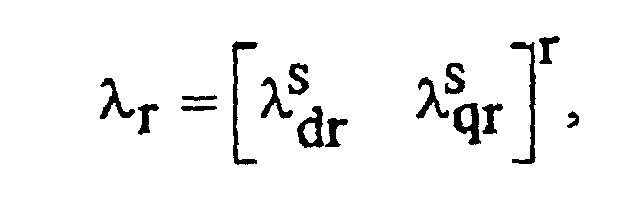


- i

- i

- λ

- λ

- v

- v

- ωr = rotor speed, and
- θr = rotor position.
- An
observer 210 for the equations (3) and (4) is constituted in the following manner.


- C1 = [0 1]; and
- G = observer gain matrix.
- In the
state observer 210, a superposed frequency is removed and output from afeedback signal 233 and aninput signal 234 by a superposedfrequency component remover 230. This is required for removing the influence of a high frequency superposing signal. An estimated magnetic flux 227 is converted into amagnetic flux quantity 225 and aphase angle 226 by means of a magneticflux quantity calculator 223 and a magneticflux position calculator 224. - An
output 241 of the initial magnetic flux estimator represents a sign for determining an N pole or an S pole after the position of a magnetic pole is estimated into 0 or π before starting and serves to carry out a multiplication over the following matrix N, thereby correcting an initial magnetic flux.
- Fig. 3 is a diagram showing the details of the high
frequency component extractor 130 in Fig. 1. The high frequency component extractor serves to extract, from a voltage or current detection signal having the same frequency component as the frequency component of the superposed high frequency signal, the error signal of a magnetic flux position obtained based on the magnetic saliency of the physical quantity of an electric motor in a high frequency region generated by a magnetic saturation caused by amainmagnetic flux or a skin effect producedby a high frequency. In the embodiment, the same error signal is extracted from the current detection signal. The high frequency component extractor is constituted by a superposed frequencycomponent extracting unit 310 for extracting a superposed high frequency component from a detection voltage or current and a magnetic flux position errorsignal calculating unit 320 for calculating the error signal of a magnetic flux position. - In the case in which an estimated
magnetic flux position 301 is not coincident with a true value, a high frequency current is generated on a q axis with a high frequency voltage superposed on a d axis of a rotary coordinate system. In order to estimate the magnetic flux position, accordingly, the high frequency signal is superposed on the estimatedmagnetic flux position 301. In the starting of the electric motor, an optional axis is assumed to be the estimatedmagnetic flux position 301. In order to detect the influence of the superposed high frequency, an orthogonal detection coordinatesystem 302 is put. The coordinate system is put in a π/4 radian lag phase from the estimatedmagnetic flux position 301. If the estimatedmagnetic flux position 301 is placed between an actual magnetic flux axis and an axis which is orthogonal thereto, a high frequency component detected by the detection coordinatesystem 302 has the magnetic saliency of a high frequency impedance. For this reason, a difference is made on a value over the reference axis (d axis) of the detection coordinate and the axis (q axis) which is orthogonal thereto. If it is assumed that an admittance at the superposed frequency is distributed in a bending shape and is symmetrical with respect to the actual magnetic flux axis, the magnitude of an admittance with a superposed frequency at an optional phase angle can be expressed in the following manner.

- If a high frequency voltage having a frequency ωi and an amplitude Vdsi* is superposed on an estimated magnetic flux axis, a relationship between a voltage and a current in the detection coordinate
system 302 can be expressed in the following manner.


- In the invention, a primary current 303 is converted into the detection coordinate system by means of a coordinate
converter 311. Only the superposed frequency component of a current 305 obtained by the conversion is extracted by means of a band-pass filter 312. The amplitude of acurrent signal 306 thus extracted is distributed intoamplitude calculators unit 321 and square values thereof are obtained by theamplitude calculators 
- The error signal is corrected through an
output Kci 337 of a compensator in the following manner in order to compensate for an estimated error or to maintain a magnetic saliency.
- The
Kci 337 will be described with reference to the following Fig. 5. - Fig. 4 is an explanatory diagram showing the details of the hybrid device 140 (410 in Fig. 4) and the speed estimator 150 (450 in Fig. 4) in Fig. 1. An error signal ε1 corresponding to a speed estimation error is constituted by a state estimation quantity through an observer in the following manner.

- In middle and high speed regions, accurate information about a magnetic fluxpositioncannot be obtained, due to a voltage limitation, from an
error signal εi 412 calculated in the equations (5) and (6). For this reason, a signal is to be removed depending on a speed. Therefore, an error signal is newly generated from theerror signal 412 calculated in the equation (5) by using a transfer function of G3(s) 433.
- The
speed estimator 450 has a proportional integration (PI)regulator 460 and the gain of anerror signal ε 1 411 is regulated to set anerror signal ε 2 412 to be zero. The responsiveness of theerror signal ε 1 411 and theerror signal ε 2 412 and the regulated gain are different from each other. For this reason, the regulation can be separately carried out as in again 470 corresponding to an error signal ε1 (an error signal on an observer side) and again 480 corresponding to the error signal ε2 412 (an error signal based on a high frequency superposition). ThePI regulator 460 regulates the error signals to be zero, and at the same time, estimates aspeed 451. - Fig. 5 illustrates the high frequency generator and
magnetic flux regulator 110 in Fig. 1. The high frequency generator andmagnetic flux regulator 110 outputs a high frequency signal vsi e* 515 to be superposed on the estimated magnetic flux axis, a magnetic flux command regulation value λrc* 521 for regulating the magnitude of a magnetic flux in order to obtain the magnetic saliency of the physical quantity of an electric motor in such a manner that a magnetic flux position can be detected on a load condition, and aregulation gain Kci 531 for regulating a magnetic flux position on which a high frequency is to be superposed. - An
amplitude 511 of a high frequency signal is determined by a previously mapped table 510 on acondition 541 obtained in the following equation.
- The magnetic flux command regulation value λrc* 521 is determined by a previously mapped table 520. The maximum value of a magnetic flux command regulation level is equivalent to a condition that the magnetic saliency of the physical quantity of an electric motor is maximized, and is based on a characteristic which is peculiar to the electric motor. The condition of the regulation is set to be a
condition 545 which is determined in the following equation.
- A method for detecting a magnetic flux position through a high frequency superposition is based on the characteristic of an impedance or admittance of the high frequency region of a synchronous motor. A condition that the saliency of the impedance of the high frequency region is shown in Figs. 6 and 7. Fig. 6 shows that an angle indicative of the degree of the saliency of the impedance is delayed in a phase based on the inductance characteristic of the synchronous motor when an operation frequency is increased. Fig. 7 shows that the angle indicative of the degree of the saliency of the impedance is delayed in the phase due to the saturation of the primary leakage inductance of the synchronous motor when a load is increased (a q-axis current is increased). The
regulation gain Kci 531 for correcting an angle error made by the phenomenon is determined in the following equation.
- Herein, a magnetic flux position is different from a rotor position in some cases, and there is provided a table 560 for compensating for an error between the magnetic flux position and the rotor position based on the characteristic of the electric motor.
- Next, a second embodiment according to the invention will be described with reference to the drawings.
- Fig. 8 is a diagram showing the structure of a sensorless control apparatus of an AC motor according to the second embodiment of the invention.
- Fig. 9 is a diagram showing the details of a high frequency component extractor illustrated in Fig. 8.
- Fig. 10 is a diagram showing the details of a high frequency generator and a magnetic flux regulator illustrated in Fig. 8.
- Fig. 11 is a chart showing the characteristic of a double harmonic in the case in which a voltage high frequency is superposed in an initial magnetic pole estimator illustrated in Fig. 8.
- Fig. 12 is an explanatory diagram showing the initial magnetic pole estimator illustrated in Figs. 1 and 8.
- Fig. 8 is a diagram showing the structure of a sensorless control apparatus of an AC motor according to the second embodiment of the invention, illustrating a method for superposing a high frequency current. While the method is similar to the method for superposing a high frequency voltage in Fig. 1, it is different therefrom in that a
high frequency signal 812 is superposed on the input portion of acurrent controller 870 and a superposing signal remover (corresponding to 180 in Fig. 1) is erased from a detection current feedback portion. The repetitive description of other identical structures to those in Fig. 1 will be omitted. - Next, an operation will be described with reference to each of the drawings.
- Fig. 9 illustrates a high
frequency component extractor 830 in Fig. 8. Assuming that an impedance is distributed in a bending shape at a superposed frequency and is symmetrically with respect to an actual magnetic flux axis, an impedance with a superposed frequency at an optional phase angle can be expressed in the following manner.
- If a high frequency current having a frequency ωi and an amplitude idsie* is superposed on an estimated magnetic flux axis, a relationship between a voltage and a current in a detection coordinate
system 902 can be expressed in the following manner.


- In the invention, a
primary voltage 903 is converted into the detection coordinate system by means of a coordinateconverter 911. Only the superposed frequency component of avoltage 905 obtained by the conversion is extracted by means of a band-pass filter 912.Square values voltage signal 906 thus extracted are calculated inamplitude calculators 
- Fig. 10 illustrates a high frequency generator and
magnetic flux regulator 810 in Fig. 8. The high frequency generator and magnetic flux regulator 810 (Fig. 8) outputs a high frequency signal isi e* 965 to be superposed on an estimated magnetic flux axis, a magnetic flux command regulation value λrc^ 971 for regulating the magnitude of a magnetic flux in order to obtain the magnetic saliency of the physical quantity of an electric motor in such a manner that a magnetic flux position can be detected on a load condition, and aregulation gain Kci 981 for regulating a magnetic flux position on which a high frequency is to be superposed. - In some cases in which a sensorless control is to be carried out by means of a permanent magnet synchronous motor, subsequently, a reverse rotation is generated depending on a starting method. An initial magnetic pole position is to be estimated in a stoppage state before starting. A large number of conventional methods utilize the saturation characteristic of a core magnetic flux. In the invention, a high frequency is superposed and a signal related to the physical quantity of the motor in the superposed frequency component is utilized. An N magnetic pole position can be estimated by a change in the physical quantity of the motor based on a hysteresis in the magnetic saturation of the core magnetic flux and the position of a rotor.
- If a high frequency is superposed on an estimated magnetic flux axis (d axis), it is distorted by the influence of the hysteresis. The cycle of a distorted waveform generates a frequency which is even-numbered times as high as the superposed frequency. In the case in which a voltage is superposed, the phenomenon appears on a current. In the case in which the current is superposed, the phenomenon appears on the voltage. Herein, an explanation will be given to an example in which an initial magnetic pole is estimated by using a high frequency which is a double of the superposed frequency.
- Fig. 11 shows the characteristic of a high frequency current to be the double frequency of the superposed frequency (which will be hereinafter referred to as a double harmonic) in the case in which a voltage high frequency is superposed. In Fig. 11, an 'A' region indicates the track of the double harmonic obtained when a high frequency signal is superposed in the direction of the N pole of a magnet, that is, the direction of the d axis, and a 'B' region indicates the track of a double harmonic obtained when the high frequency signal is superposed in the direction of the S pole of themagnet, that is, the direction of a -d axis. At this time, the double harmonic can be detected in the following manner.


- i

- i

- BPF : a band-pass filter for extracting the double harmonic of the superposing signal,
- Idsin2ωh : an amplitude of the reactive component of the double harmonic of the superposing signal,
- Idcos2ωh : an amplitude of the effective component of the double harmonic of the superposing signal,
- LPF : a low-pass filter for removing a high frequency component
- φ : a phase angle of the double harmonic of the superposing signal.
- As shown in Fig. 11, the phase angle of the double harmonic of the superposing signal represents the direction of a +d axis in the case in which it is positioned at φ [radian] and φ + π [radian], and represents the direction of the -d axis in the other cases. Accordingly, it is possible to discriminate the N and S poles of an initial magnetic pole.
- Fig. 12 shows a method for estimating an initial magnetic pole position according to the invention. By the estimation of a magnetic flux position through a high frequency superposition before starting, an initial magnetic flux position is estimated. At the same time, the initial magnetic pole position is estimated by utilizing the characteristic of the double harmonic component of the superposed frequency. The estimation of the magnetic pole position can be calculated in a signal processing to be one step in the following manner.

- If Ldsin2ωhφ is positive, the N pole and the d axis are coincident with each other. To the contrary, if the Ldsin2ωhφ is negative, the N pole is provided in a reverse direction to the d axis. Accordingly, if the Ldsin2ωhφ is negative, the N pole and the d axis are caused to be coincident with each other by adding π to a magnetic flux position estimated in an initial state. A time (TIME) required for correcting the polarity of the magnetic flux position can be set optionally. If the d axis and the N pole are once coincident with each other, the method for estimating a magnetic flux position through a high frequency superposition rarely misses the magnetic pole position in a low-speed driving operation.
- The embodiment has described the basic features of the invention. While partial improvements and the replacement of functions can be made, the appended claims include all of the improvements and the replacement of the functions in a basic concept.
- Next, a third embodiment according to the invention will be described with reference to the drawings.
- Fig. 13 is a diagram showing the structure of a sensorless control apparatus of anAC motor according to the third embodiment of the invention.
- Fig. 14 is a diagram showing the details of a magnetic flux observer illustrated in Fig. 13.
- Fig. 15 is a diagram showing the details of a hybrid device and a speed estimator illustrated in Fig. 13.
- Fig. 16 is a diagram showing the details of a high frequency generator and magnetic flux regulator illustrated in Fig. 13.
- While the example of the AC motor (synchronous motor) has been described in the above embodiments, an induction motor will be described in the embodiment. A control block shown in Fig. 13 can be implemented through a digital operation in order to drive an AC motor (induction motor) 101 in the same manner as in Fig. 1 by using a
voltage type inverter 102. Moreover, the same control block can also be implemented by using an analog circuit or using the analog circuit and a digital circuit together. - In Fig. 13, in the same manner as the structure in Fig. 1, a
sensorless control apparatus 100 has a high frequency generator andmagnetic flux regulator 110 and the high frequency generator serves to superpose a high frequency signal on the estimated magnetic flux axis of an electric motor. The magnetic flux regulator regulates the magnetic saliency of the physical quantity of the electric motor in a high frequency region and regulates a magnetic flux command in order to compensate for a magnetic flux estimation error. Moreover, the error of a magnetic flux position which is made by a load is regulated in a magnetic flux position in which a high frequency is to be superposed. - A
magnetic flux observer 120 estimates the magnitude and position of a magnetic flux from an electric motor input voltage, a detection current and a speed estimation value. Afrequency component extractor 130 extracts, from a voltage or current detection signal having the same frequency component as the frequency component of a high frequency signal, an error signal of a magnetic flux position obtained based on the magnetic saliency of the physical quantity of an electric motor in a high frequency region generated by a magnetic saturation caused by a main magnetic flux or a skin effect produced by a high frequency. Ahybrid device 140 serves to switch an adaptive regulator for adaptively regulating the error signal of the magnetic flux position to be the output of a high frequency component extractor and an adaptive regulator for adaptively regulating an error signal calculated from a magnetic flux estimation value and the error value of the output of the magnetic flux observer in the same observer from a low speed to a high speed depending on the speed without a shock. - A
speed estimator 150 serves to adaptively estimate a speed in order to set, to be zero, the error signal to be the output value of the hybrid device. Moreover, the sensorless control apparatus has a magnetic flux andspeed controller 160 and acurrent controller 170. There is required asuperposed frequency remover 180 for removing a superposed frequency component from a current fed back to thecurrent controller 170. Thedevice 180 for removing the superposed frequency component is constituted by a low-pass filter or a notch filter. Consequently, avoltage command value 171 to be the output of thecurrent controller 170 does not include a superposed frequency component. By using the estimated magnetic flux position, coordinatetransformers 

- In the embodiment shown in Fig. 13, thus, the
induction motor 101 is controlled with the same structure and control method as that in the control block shown in Fig. 1, and the embodiment is different from Fig. 1 in that therotor position estimator 135 and the initial magneticpole position estimator 136 are deleted. - Fig. 14 shows the internal structure of the
magnetic flux observer 120 in Fig. 13. The formula model of the induction motor in a static coordinate system can be expressed in the following manner.

- In the equations (7) and (4),


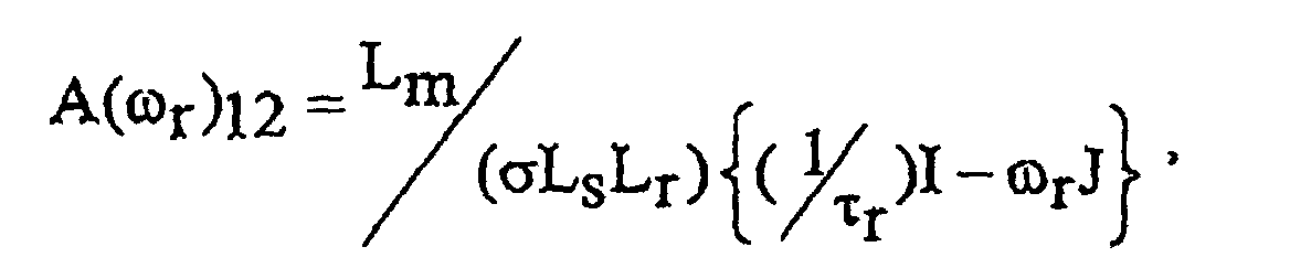


- i

- i

- λ

- λ

- v

- v

- ωr = rotor speed.
- An
observer 210 for the equations (7) and (4) is constituted in the following manner.


- Other matrices are as follows:
- C1 = [0 1]; and
- G = observer gain matrix.
- In the
state observer 210, a superposed frequency is removed and output from afeedback signal 233 and aninput signal 234 by means of a superposedfrequency component remover 230. This is required for removing the influence of a high frequency superposing signal. An estimatedmagnetic flux 227 is converted into amagnetic flux quantity 225 and aphase angle 226 by means of a magneticflux quantity calculator 223 and a magneticflux position calculator 224. - In Fig. 14, the output of an initial magnetic flux estimator is omitted.
- Referring to the explanation of the high
frequency component extractor 130 in Fig. 13, next, a structure is the same and description will be therefore given by sharing Fig. 3 in the above embodiment. The highfrequency component extractor 130 serves to extract, from a voltage or current detection signal having the same frequency component as the frequency component of the superposed high frequency signal, the error signal of a magnetic flux position obtained based on the magnetic saliency of the physical quantity of an electric motor in a high frequency region generated by a magnetic saturation causedby amain magnetic flux or a skin effect produced by a high frequency. - Herein, the same error signal is extracted from the current detection signal. The high frequency component extractor is constituted by a superposed frequency
component extracting unit 310 for extracting a superposed high frequency component from a detection voltage or current and a magnetic flux position errorsignal calculating unit 320 for calculating the error signal of a magnetic flux position. - In the case in which an estimated
magnetic flux position 301 is not coincident with a true value, a high frequency current is generated on a q axis with a high frequency voltage superposed on a d axis of a rotary coordinate system. In order to estimate the magnetic flux position, accordingly, the high frequency signal is superposed on the estimatedmagnetic flux position 301. In the starting of the electric motor, an optional axis is assumed to be the estimatedmagnetic flux position 301. In order to detect the influence of the superposed high frequency, an orthogonal detection coordinatesystem 302 is put. The coordinate system is put in a π/4 radian lag phase from the estimatedmagnetic flux position 301. If the estimatedmagnetic flux position 301 is placed between an actual magnetic flux axis and an axial which is orthogonal thereto, a high frequency component detected by the detection coordinatesystem 302 has the magnetic saliency of a high frequency impedance. For this reason, a difference is made on a value over the reference axis (d axis) of the detection coordinate and the axis (q axis) which is orthogonal thereto. If it is assumed that an admittance at the superposed frequency is distributed in a bending shape and is symmetrical with respect to the actual magnetic flux axis, the magnitude of an admittance with a superposed frequency at an optional phase angle can be expressed in the following manner.

- If a high frequency voltage having a frequency ωi and an amplitude vdsi* is superposed on an estimated magnetic flux axis, a relationship between a voltage and a current in the detection coordinate
system 302 can be expressed in the following manner.
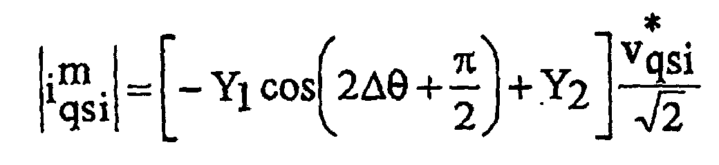


- In the invention, a primary current 303 is converted into the detection coordinate system by means of a coordinate
converter 311. Only the superposed frequency component of a current 305 obtained by the conversion is extracted by means of a band-pass filter 312.Square values current signal 306 thus extracted are calculated in theamplitude calculators 
- The error signal is corrected through an
output Kci 337 of a compensator in the following manner in order to compensate for an estimated error or to maintain a magnetic saliency.
- The
Kci 337 will be described with reference to the following Fig. 16. - Fig. 15 illustrates the hybrid device 140 (410 in Fig. 15) and the speed estimator 150 (450 in Fig. 15) in Fig. 13. An error signal ε1 corresponding to a speed estimation error is constituted by a state estimation quantity through an observer in the following manner.

- In middle and high speed regions, accurate information about amagnetic fluxposition cannot be obtained, due to a voltage limitation, from an
error signal εi 412 calculated in the equations (5) and (6). For this reason, a signal is to be removed depending on a speed. Therefore, an error signal ε2 is newly generated from theerror signal εi 412 calculated in the equation (6) by using a transfer function of G2(s) 433.
- The
speed estimator 450 has a proportional integration (PI)regulator 460 and the gain of anerror signal ε1 411 is regulated to set anerror signal ε 2 412 to be zero. The responsiveness of theerror signal ε 1 411 and theerror signal ε 2 412 and the regulated gain are different from each other. For this reason, the regulation can be separately carried out as in again 470 corresponding to the error signal ε1 (an error signal on an observer side) and again 480 corresponding to the error signal ε2 412 (an error signal based on a high frequency superposition). ThePI regulator 460 regulates the error signals to be zero, and at the same time, estimates aspeed 451. - Fig. 16 illustrates the high frequency generator and
magnetic flux regulator 110 in Fig. 13. The high frequency generator andmagnetic flux regulator 110 outputs a high frequency signal vsi e* 515 to be superposed on an estimated magnetic flux axis, a magnetic flux command regulation value λrc* 521 for regulating the magnitude of a magnetic flux in order to obtain the magnetic saliency of the physical quantity of an electric motor in such a manner that a magnetic flux position can be detected on a load condition, and aregulation gain Kci 531 for regulating a magnetic flux position on which a high frequency is to be superposed. - An
amplitude 511 of a high frequency signal is determined by a previously mapped table 510 on acondition 541 obtained in the following equation.
- The magnetic flux command regulation value λrc* 521 is determined by a previously mapped table 520. The maximum value of a magnetic flux command regulation level is equivalent to a condition that the magnetic saliency of the physical quantity of an electricmotor is maximized, and is based on a characteristic which is peculiar to the electric motor. The condition of the regulation is set to be a
condition 545 which is determined in the following equation.
- A method for detecting a magnetic flux position through a high frequency superposition is based on the characteristic of an impedance or admittance of the high frequency region of an induction motor. A condition that the saliency of the impedance of the high frequency region makes a loss will be described with reference to Figs. 6 and 7 according to the above embodiment. Fig. 6 shows that an angle indicative of the degree of the saliency of the impedance is also delayed in a phase based on the inductance characteristic in the induction motor when an operation frequency is increased. Fig. 7 shows that the angle indicative of the degree of the saliency of the impedance is also delayed in the phase due to the saturation of the primary leakage inductance in the induction motor when a load is increased (a q-axis current is increased). The
regulation gain Kci 531 for correcting an angle error made by the phenomenon is determined in the following equation.
- Next, a fourth embodiment according to the invention will be described with reference to the drawings.
- Fig. 17 is a diagram showing the structure of a sensorless control apparatus of an AC motor according to the fourth embodiment of the invention.
- Fig. 18 is a diagram showing the details of a high frequency generator and magnetic flux regulator illustrated in Fig. 17.
- Fig. 17 shows a method for superposing a high frequency current as the fourth embodiment. While the method is similar to the method for superposing a high frequency voltage in Fig. 13, it is different therefrom in that a
high frequency signal 812 is superposed on the input portion of acurrent controller 870 and a superposing signal remover is erased from a detection current feedback portion. - Since the diagram showing the details of a high
frequency component extractor 830 in Fig. 17 is the same as that of Fig. 9 according to the second embodiment, description will be given with reference to Fig. 9. Assuming that an impedance is distributed in a bending shape at a superposed frequency and is symmetrically with respect to an actual magnetic flux axis, an impedance with a superposed frequency at an optional phase angle can be expressed in the following manner.
- If a high frequency current having a frequency ωi and an amplitude idsi e* is superposed on an estimated magnetic flux axis, a relationship between a voltage and a current in a detection coordinate
system 902 can be expressed in the following manner.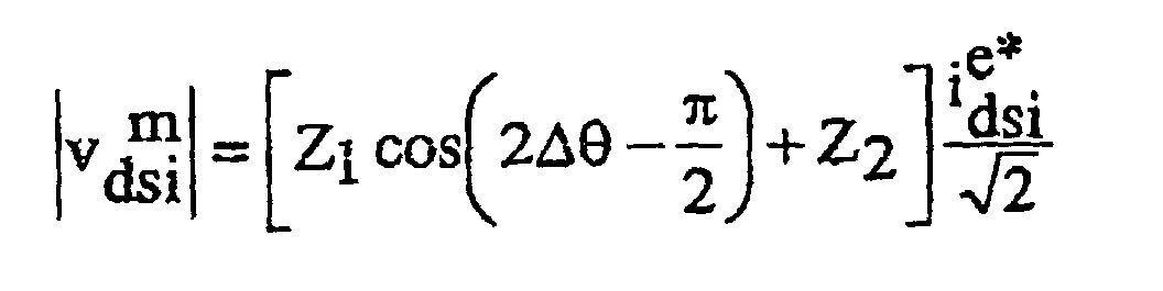
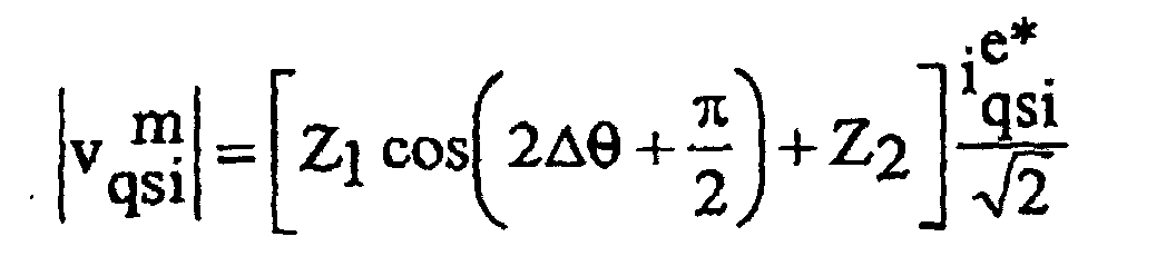


- In the invention, a
primary voltage 903 is converted into the detection coordinate system by means of a coordinateconverter 911. only the superposed frequency component of avoltage 905 obtained by the conversion is extracted by means of a band-pass filter 912.Square values voltage signal 906 thus extracted are calculated inamplitude calculators 
- Fig. 18 illustrates a high frequency generator and
magnetic flux regulator 810 in Fig. 17. The high frequency generator andmagnetic flux regulator 810 outputs a high frequency signal isi e* 965 to be superposed on an estimated magnetic flux axis, a magnetic flux command regulation value λrc^ 971 for regulating the magnitude of a magnetic flux in order to obtain the magnetic saliency of the physical quantity of an electric motor in such a manner that a magnetic flux position can be detected on a load condition, and aregulation gain Kci 981 for regulating a magnetic flux position on which a high frequency is to be superposed. - The above embodiments have described the basic features of the invention. While partial improvements and the replacement of functions can be made, the invention includes all of the improvements and the replacement of the functions in a basic concept in the appended claims.
- While the invention has been described in detail with reference to the specific embodiments, it is apparent to the skilled in the art that various changes and modifications can be made without departing from the spirit and scope of the invention.
- The application is based on Japanese Patent Application (JP-A-2002-100259) filed on April 2, 2002 and the contents thereof are incorporated by reference.
- As described above, according to the invention, it is possible to produce such an advantage as to provide a sensorless control method and apparatus of an AC motor to implement stable torque and speed controls within all driving ranges including a region having a zero speed and a zero output frequency without generating a torque vibration element such as a voltage error or a noise even if a high frequency is superposed.
Claims (36)
- A sensorless control apparatus of an AC motor which separates a motor current into a magnetic flux component and a torque component based on an estimated magnetic flux position of a synchronous motor without using position and speed sensors and independently controls each of them, thereby implementing a high control performance of the synchronous motor, comprising:ahigh frequency generator for superposing a high frequency signal on an estimated magnetic flux axis of the motor;a high frequency component extractor for extracting, from a voltage or current detection signal having the same frequency component as a frequency component of the high frequency signal, an error signal of the magnetic flux position which is obtained based on a magnetic saliency of a physical quantity of the motor in a high frequency region generated by a magnetic saturation causedby a main magnetic flux or a conductor skin effect produced by a high frequency;a magnetic flux observer for estimating a magnitude and a position of a magnetic flux from a motor input voltage, a detection current and a speed estimation value;a first adaptive regulator for adaptively regulating an error signal of a magnetic flux position to be an output of the high frequency component extractor;a second adaptive regulator for adaptively regulating an error signal calculated from a magnetic flux estimation value and an error value of an output of the magnetic flux observer in the same observer;a hybrid device for switching the first adaptive regulator at a very low speed, the first and second adaptive regulators at a low speed and the second adaptive regulator at a high speed depending on the speed; anda speed estimator for generating a speed estimation value from an output value of the hybrid device.
- The sensorless control apparatus of an AC motor according to claim 1, further comprising a magnetic flux regulator for regulating a magnetic flux levels regulating a magnetic saliency of a physical quantity of the motor in a high frequency region and regulating an efficiency;
an estimated error corrector for correcting an estimated error made in an estimated magnetic flux, an estimated rotor speed and an estimated rotor position;
a magnetic flux position calculator for calculating a position of a magnetic flux from the magnetic flux estimated from the magnetic flux observer;
a current controller for separating a detection current into a magnetic flux direction component and a torque component by using an estimated magnetic flux position, feeding back each of them and comparing the magnetic flux direction component with a current command value of the torque component, thereby carrying out a current control in such a manner that each deviation is set to be zero;
a speed controller for comparing an estimated speed with a command speed to execute a speed control in such a manner that a deviation thereof is set to be zero, thereby outputting a torque command value or a current command value corresponding to a torque command; and
an initial magnetic pole position estimator for estimating an initial magnetic pole position before starting. - The sensorless control apparatus of an AC motor according to claim 1, wherein the high frequency generator includes a device for regulating a high frequency signal to be superposed depending on a rotating speed of a magnetic flux or a rotor speed.
- The sensorless control apparatus of an AC motor according to claim 1, wherein the high frequency generator superposes a high frequency signal on a voltage command value.
- The sensorless control apparatus of anAC motor according to claim 1, wherein the high frequency generator superposes a high frequency signal on a current command value.
- The sensorless control apparatus of an AC motor according to claim 1, wherein the magnetic flux observer has a function of removing the high frequency signal from a motor input voltage depending on an output frequency or a speed.
- The sensorless control apparatus of an AC motor according to claim 1, wherein an error signal of a magnetic flux position obtained in the high frequency component extractor is based on an impedance or an admittance in a high frequency region which is superposed.
- The sensorless control apparatus of an AC motor according to claim 1, wherein the hybrid device has a function of removing an output of the second adaptive regulator in a very low speed region including a zero speed and has a function of removing an output of the first adaptive regulator in middle and high speed regions.
- The sensorless control apparatus of an AC motor according to claim 1, wherein the speed estimator adaptively estimates a speed in order to set an error signal to be an output value of the hybrid device to be zero.
- The sensorless control apparatus of an AC motor according to claim 2, wherein the magnetic flux regulator regulates a magnetic flux level into a portion in which a characteristic of the motor, that is, a magnetic saliency of a physical quantity of the motor in a high frequency region can be maintained and a high efficiency can be obtained, and the estimated error corrector corrects an estimatedmagnetic flux, an estimated rotor speed and an estimated rotor position error which are generated when the magnetic saliency at the high frequency is reduced.
- The sensorless control apparatus of an AC motor according to claim 2, wherein the current controller has a function of removing a superposed high frequency component from a current which is fed back when the high frequency signal to be superposed is a voltage and a response frequency of the controller is set to be higher than a superposed frequency component when the high frequency signal to be superposed is a current.
- The sensorless control apparatus of an AC motor according to claim 2, wherein the initial magnetic pole position estimator has a signal processing portion for extracting at least one frequency of harmonics which are nth power of 2 (N = -1, 1, 2, 3, ···, n) of the superposed high frequency and serves to discriminate an N or S pole of a magnetic pole.
- A sensorless control method of an AC motor which separates a motor current into a magnetic flux component and a torque component based on an estimated magnetic flux position of a synchronous motor without using position and speed sensors and independently controls each of them, thereby implementing a high control performance of the synchronous motor, comprising:means for superposing a high frequency signal on an estimated magnetic flux axis of the motor;means for extracting, from a voltage or current detection signal having the same frequency component as a frequency component of the high frequency signal, an error signal of the magnetic flux position obtained based on a magnetic saliency of a physical quantity of the motor in a high frequency region generated by a magnetic saturation caused by a main magnetic flux or a conductor skin effect produced by a high frequency;means for estimating a magnitude and a position of a magnetic flux from a motor input voltage, a detection current and a speed estimation value through a magnetic flux observer;first adaptive rule means for adaptively regulating an error signal of a magnetic flux position to be an output of the high frequency component extractor;second adaptive rule means for adaptively regulating an error signal calculated from a magnetic flux estimation value and an error value of an output of the magnetic flux observer in the same observer;means for switching the first and second adaptive rule means depending on a speed; andmeans for estimating a speed from an output signal of the adaptive rule means.
- The sensorless control method of an AC motor according to claim 13, further comprising means for regulating a magnetic flux in order to maintain a magnetic saliency of a physical quantity of the motor in a high frequency region and to hold a high efficiency;
an estimated error corrector for correcting an estimated error made in an estimated magnetic flux, an estimated rotor speed and an estimated rotor position;
means for calculating a position of a magnetic flux from amagnetic flux vector estimated from the magnetic flux observer;
means for separating a detection current into a magnetic flux direction component and a torque component by using an estimated magnetic flux position, feeding back each of them and comparing the magnetic flux direction component with a current command value of the torque component, thereby carrying out a current control in such a manner that each deviation is set to be zero;
means for comparing an estimated speed with a command speed to execute a speed control in such a manner that a deviation thereof is set to be zero, thereby outputting a torque command value or a current command value corresponding to a torque command; and
initial magnetic pole estimating means for discriminating an N or S pole of a magnetic pole before starting. - The sensorless control method of an AC motor according to claim 13, wherein the means for switching the adaptive rule means depending on a speed has a function of removing an output signal of the second adaptive rule means in a very low speed region including a zero speed and a zero frequency and has a function of removing an output signal of the first adaptive rule means in middle and high speed regions.
- The sensorless control method of an AC motor according to claim 13, wherein the means for extracting an error signal of a magnetic flux position obtained based on a magnetic saliency of a physical quantity of the motor uses the physical quantity of the motor including a motor input voltage command value and a detection current or a detection voltage and the detection current.
- The sensorless control method of an AC motor according to claim 13, wherein the means for superposing a high frequency has means for regulating a high frequency signal to be superposed depending on an output frequency or a speed.
- The sensorless control method of an AC motor according to claim 14, wherein the means for regulating a magnetic flux serves to regulate a magnitude of a magnetic flux in order to obtain a magnetic saliency of a physical quantity of the motor in such a manner that a magnetic flux position can be detected depending on a peculiar characteristic to the motor at a very low speed including a zero speed and a zero frequency and an error of a magnetic flux position which is made by a load is regulated in a magnetic flux position on which a high frequency is to be superposed, the regulating means carrying out a regulation through an estimated error and a stator (primary) current or a command current.
- The sensorless control method of an AC motor according to claim 14, wherein the initial magnetic pole estimating means has a signal processing portion for extracting at least one frequency of harmonics which are nth power of 2 (N = -1, 1, 2, 3, ···, n) of the superposed high frequency and serves to discriminate an N or S pole of a magnetic pole.
- A sensorless control apparatus of an AC motor which separates a motor current into a magnetic flux component and a torque component based on an estimation value of a magnetic flux position of an induction motor without using a speed sensor and independently controls each of them, thereby implementing a high control performance of the induction motor, comprising:a high frequency generator for superposing a high frequency signal on an estimated magnetic flux axis of the motor;a high frequency component extractor for extracting, from a voltage or current detection signal having the same frequency component as a frequency component of the high frequency signal, an error signal of the magnetic flux position obtained based on a magnetic saliency of a physical quantity of the motor in a high frequency region generated by a magnetic saturation caused by a main magnetic flux or a conductor skin effect produced by a high frequency;a magnetic flux observer for estimating a magnitude and a position of a magnetic flux from a motor input voltage, a detection current and a speed estimation value;a third adaptive regulator for adaptively regulating an error signal of a magnetic flux position to be an output of the high frequency component extractor;a fourth adaptive regulator for adaptively regulating an error signal calculated from a magnetic flux estimation value and an error value of an output of the magnetic flux observer in the same observer;a hybrid device for switching the third adaptive regulator at a very low speed, the third and fourth adaptive regulators at a low speed and the fourth adaptive regulator at a high speed depending on the speed; anda speed estimator for generating a speed estimation value from an output value of the hybrid device.
- The sensorless control apparatus of an AC motor according to claim 20, further comprising a magnetic flux regulator for regulating a magnetic flux command and a magnetic flux position on which a high frequency signal is to be superposed in order to adjust a magnetic saliency of a physical quantity of the motor in a high frequency region;
a magnetic flux position calculator for calculating a position of a magnetic flux from the magnetic flux estimated from the magnetic flux observer;
a current controller for separating a detection current into a magnetic flux direction component and a torque component by using the calculated magnetic flux position, feeding back each of them and comparing the magnetic flux direction component with a current command value of the torque component, thereby carrying out a current control in such a manner that each deviation is set to be zero; and
a speed controller for comparing an estimated speed with a command speed to execute a speed control in such a manner that a deviation thereof is set to be zero, thereby outputting a torque command value or a current command value corresponding to a torque command. - The sensorless control apparatus of an AC motor according to claim 20, wherein the high frequency generator includes a device for regulating a high frequency signal to be superposed depending on an output frequency or a speed.
- The sensorless control apparatus of an AC motor according to claim 20, wherein the high frequency generator superposes a high frequency signal on a voltage command value.
- The sensorless control apparatus of an AC motor according to claim 20, wherein the high frequency generator superposes a high frequency signal on a current command value.
- The sensorless control apparatus of an AC motor according to claim 20, wherein the magnetic flux observer has a function of removing the high frequency signal from a motor input voltage depending on an output frequency or a speed.
- The sensorless control apparatus of an AC motor according to claim 20, wherein an error signal of a magnetic flux position obtained in the high frequency component extractor is based on an impedance or an admittance in a high frequency region which is superposed.
- The sensorless control apparatus of an AC motor according to claim 20, wherein the hybrid device has a function of removing an output of the fourth adaptive regulator in a very low speed region including a zero speed and a zero frequency, and has a function of removing an output of the third adaptive regulator in middle and high speed regions.
- The sensorless control apparatus of an AC motor according to claim 20, wherein the speed estimator adaptively estimates a speed in order to set an error signal to be an output value of the hybrid device to be zero.
- The sensorless control apparatus of an AC motor according to claim 21, wherein the magnetic flux regulator has a function of regulating a magnitude of a magnetic flux in order to obtain a magnetic saliency of a physical quantity of the motor in such a manner that a magnetic flux position can be detected depending on a peculiar characteristic to the motor and a function of regulating an error of a magnetic flux position which is made by a load in a magnetic flux position on which a high frequency is to be superposed.
- The sensorless control apparatus of an AC motor according to claim 21, wherein the current controller has a function of removing a superposed frequency component from a current fed back when the high frequency signal to be superposed is a voltage, and a response frequency of the controller is set to be higher than the superposed frequency component when the high frequency signal to be superposed is a current.
- A sensorless control method of an AC motor which separates a motor current into a magnetic flux component and a torque component based on an estimation value of amagnetic flux position of an induction motor without using a speed sensor and independently controls each of them, thereby implementing a high control performance of the induction motor, comprising:means for superposing a high frequency signal on an estimated magnetic flux axis of the motor;means for extracting, from a voltage or current detection signal having the same frequency component as a frequency component of the high frequency signal, an error signal of the magnetic flux position obtained based on a magnetic saliency of a physical quantity of the motor in a high frequency region generated by a magnetic saturation caused by a main magnetic flux or a conductor skin effect produced by a high frequency;means for estimating a magnitude and a position of a magnetic flux from a motor input voltage, a detection current and an estimated speed through a magnetic flux observer;third adaptive rule means for adaptively regulating an error signal of a magnetic flux position to be an output of the high frequency component extractor;fourth adaptive rule means for adaptively regulating an error signal calculated from a magnetic flux estimation value and an error value of an output of the magnetic flux observer in the same observer;means for switching the first and second adaptive rule means depending on a speed or an output frequency; andmeans for estimating a speed from an output signal of the adaptive rule means.
- The sensorless control method of an AC motor according to claim 31, further comprising means for regulating a magnetic flux in order to adjust a magnetic saliency of a physical quantity of the motor in a high frequency region;
means for calculating a position of a magnetic flux from the magnetic flux estimated from the magnetic flux observer;
means for separating a detection current into a magnetic flux direction component and a torque component by using the calculated magnetic flux position, feeding back each of them and comparing the magnetic flux direction component with a current command value of the torque component, thereby carrying out a current control in such a manner that each deviation is set to be zero; and
means for comparing an estimated speed with a command speed to execute a speed control in such a manner that a deviation thereof is set to be zero, thereby outputting a torque command value or a current command value corresponding to a torque command. - The sensorless control method of an AC motor according to claim 31, wherein the means for switching the adaptive rule means has a function of removing an output signal of the fourth adaptive rule means in a very low speed region including a zero speed and a zero frequency and a function of removing an output signal of the third adaptive rule means in middle and high speed regions.
- The sensorless control method of an AC motor according to claim 31, wherein the means for extracting an error signal of a magnetic flux position obtained based on a magnetic saliency of a physical quantity of the motor and the means for estimating a magnitude and a position of a magnetic flux by a magnetic flux observer use the physical quantity of the motor including a motor input voltage command value and a detection current or a detection voltage and the detection current.
- The sensorless control method of an AC motor according to claim 31, wherein the means for superposing a high frequency has means for regulating a high frequency signal to be superposed depending on an output frequency or a speed.
- The sensorless control method of an AC motor according to claim 32, wherein the regulating means serves to regulate a magnitude of a magnetic flux in order to obtain a magnetic saliency of a physical quantity of the motor in such a manner that a magnetic flux position can be detected depending on a peculiar characteristic to the motor at a very low speed including a zero speed and a zero frequency and an error of a magnetic flux position which is made by a load is regulated in a magnetic flux position on which a high frequency is to be superposed, the regulating means depending on an estimated speed and a stator (primary) current or a command current.
Applications Claiming Priority (3)
| Application Number | Priority Date | Filing Date | Title |
|---|---|---|---|
| JP2002100259A JP4370754B2 (en) | 2002-04-02 | 2002-04-02 | Sensorless control device and control method for AC motor |
| JP2002100259 | 2002-04-02 | ||
| PCT/JP2003/003741 WO2003084050A1 (en) | 2002-04-02 | 2003-03-26 | Sensorless controller of ac motor and control method |
Publications (1)
| Publication Number | Publication Date |
|---|---|
| EP1492224A1 true EP1492224A1 (en) | 2004-12-29 |
Family
ID=28672031
Family Applications (1)
| Application Number | Title | Priority Date | Filing Date |
|---|---|---|---|
| EP20030715432 Withdrawn EP1492224A1 (en) | 2002-04-02 | 2003-03-26 | Sensorless controller of ac motor and control method |
Country Status (6)
| Country | Link |
|---|---|
| US (1) | US7045988B2 (en) |
| EP (1) | EP1492224A1 (en) |
| JP (1) | JP4370754B2 (en) |
| CN (1) | CN1322667C (en) |
| TW (1) | TW200306059A (en) |
| WO (1) | WO2003084050A1 (en) |
Cited By (16)
| Publication number | Priority date | Publication date | Assignee | Title |
|---|---|---|---|---|
| WO2006083470A1 (en) * | 2005-01-05 | 2006-08-10 | Honeywell International Inc. | A control technique for limiting the current of an induction machine drive system |
| WO2007047296A3 (en) * | 2005-10-12 | 2007-06-21 | Ballard Power Systems | Method, apparatus and article for detecting rotor position |
| EP1852967A1 (en) * | 2006-05-03 | 2007-11-07 | LG Electronics Inc. | Apparatus for controlling high speed operation of motor and method thereof |
| EP2169820A1 (en) * | 2008-09-26 | 2010-03-31 | Kabushiki Kaisha Yaskawa Denki | Alternating-current motor control apparatus |
| EP2337211A1 (en) * | 2009-12-18 | 2011-06-22 | ABB Oy | Method and arrangement for controlling permanent magnet synchronous machines |
| RU2438229C1 (en) * | 2010-07-29 | 2011-12-27 | Государственное образовательное учреждение высшего профессионального образования "Национальный исследовательский Томский политехнический университет" | Asynchronous motor control device |
| RU2481694C1 (en) * | 2009-03-25 | 2013-05-10 | Мицубиси Электрик Корпорейшн | Control device and control method of electric rotary machine |
| CN103378775A (en) * | 2012-04-17 | 2013-10-30 | 三菱电机株式会社 | Motor control equipment and motor control system |
| WO2013149921A3 (en) * | 2012-04-04 | 2014-06-12 | Continental Automotive Gmbh | Method and device for sensorless control of a separately excited synchronous machine |
| US8884566B2 (en) | 2011-07-28 | 2014-11-11 | Vestas Wind Systems A/S | Method of position sensorless control of an electrical machine |
| US8896249B2 (en) | 2011-07-28 | 2014-11-25 | Vestas Wind Systems A/S | Method of position sensorless control of an electrical machine |
| EP2806555A1 (en) * | 2013-05-21 | 2014-11-26 | IFP Energies nouvelles | Method for determining the position and speed of a rotor of a synchronous electric machine by means of status observers |
| EP2515431A3 (en) * | 2011-04-19 | 2016-03-16 | Hitachi Industrial Equipment Systems Co., Ltd. | Electrical power conversion device and electric motor control system |
| EP2808998A4 (en) * | 2012-01-24 | 2016-06-29 | Mitsubishi Electric Corp | CONTROL DEVICE FOR AN AC POWER ROTATION MACHINE |
| EP3309954A1 (en) * | 2016-10-17 | 2018-04-18 | General Electric Company | System and method for sensorless control of electric machines using magnetic alignment signatures |
| CN111007421A (en) * | 2018-10-05 | 2020-04-14 | 操纵技术Ip控股公司 | Dynamic Estimation of Supply Current for Electric Motor Drive Systems |
Families Citing this family (106)
| Publication number | Priority date | Publication date | Assignee | Title |
|---|---|---|---|---|
| US7423395B2 (en) * | 2002-07-08 | 2008-09-09 | Kabushiki Kaisha Yaskawa Denki | Sensorless vector control method for alternating-current motor and control apparatus therefor |
| FI115873B (en) * | 2003-09-05 | 2005-07-29 | Abb Oy | Procedure in connection with a permamagnet motor with protruding poles |
| JP4691916B2 (en) * | 2003-10-29 | 2011-06-01 | ダイキン工業株式会社 | Rotational position angle estimation method, rotational position angle estimation device, motor control method, and motor control device |
| CN101014956A (en) * | 2004-07-01 | 2007-08-08 | 国际整流器公司 | Starting method and system for permanent magnet synchronous motor driver |
| US7095209B2 (en) * | 2004-09-29 | 2006-08-22 | Rockwell Automation Technologies, Inc. | Method and apparatus to regulate torque provided to loads |
| US7211984B2 (en) * | 2004-11-09 | 2007-05-01 | General Motors Corporation | Start-up and restart of interior permanent magnet machines |
| KR100665061B1 (en) * | 2004-12-08 | 2007-01-09 | 삼성전자주식회사 | Speed control device and speed control method of motor |
| JP4425193B2 (en) * | 2005-08-16 | 2010-03-03 | 三洋電機株式会社 | Motor position sensorless control device |
| JP4771126B2 (en) * | 2005-09-28 | 2011-09-14 | 富士電機株式会社 | Synchronous motor drive |
| US7466088B2 (en) * | 2005-12-16 | 2008-12-16 | Hamilton Sundstrand Corporation | Signal control for motor position determination |
| JP4899509B2 (en) * | 2006-01-07 | 2012-03-21 | 日本電産株式会社 | AC motor rotor phase estimation device |
| JP4754417B2 (en) * | 2006-06-26 | 2011-08-24 | 本田技研工業株式会社 | Control device for permanent magnet type rotating electrical machine |
| US7602139B2 (en) * | 2006-07-13 | 2009-10-13 | International Rectifier Corporation | Signal conditioning apparatus and method for determination of permanent magnet motor rotor position |
| US7932692B2 (en) * | 2006-11-13 | 2011-04-26 | Denso Corporation | Control system for rotary electric machine with salient structure |
| JP5321449B2 (en) * | 2007-03-07 | 2013-10-23 | 株式会社安川電機 | Motor control device |
| FI129765B (en) * | 2007-03-21 | 2022-08-15 | Oy Kwh Mirka Ab | Compact electric grinding machine |
| JP4587110B2 (en) * | 2007-06-01 | 2010-11-24 | 有限会社シー・アンド・エス国際研究所 | Rotor phase estimation method for synchronous motor drive control |
| JP4961292B2 (en) * | 2007-07-27 | 2012-06-27 | 三洋電機株式会社 | Motor control device |
| JP5176420B2 (en) * | 2007-08-02 | 2013-04-03 | 株式会社ジェイテクト | Sensorless control device for brushless motor |
| CN101247104B (en) * | 2008-03-27 | 2010-06-02 | 无锡市飞象电子有限公司 | Conjecture method of stator magnetic linkage oriented AC motor rotation velocity and rotor position |
| JP2009268267A (en) * | 2008-04-25 | 2009-11-12 | Sanyo Electric Co Ltd | Motor controller and generator controller |
| JP5428202B2 (en) * | 2008-05-29 | 2014-02-26 | 富士電機株式会社 | Control device for permanent magnet type synchronous motor |
| JP4751435B2 (en) * | 2008-10-09 | 2011-08-17 | 株式会社東芝 | Motor magnetic pole position detection device, motor control device, motor drive system and washing machine |
| CN102362425B (en) * | 2009-03-25 | 2014-06-04 | 三菱电机株式会社 | Controls for rotating electrical machines |
| FR2944659B1 (en) * | 2009-04-21 | 2011-04-01 | Schneider Toshiba Inverter | METHOD FOR DETERMINING THE POSITION OF THE FLOW VECTOR OF AN ENGINE |
| KR101470025B1 (en) * | 2009-07-06 | 2014-12-15 | 현대자동차주식회사 | Method of Controlling Angular Position Sensorlessness of High Efficiency Permanent Magnet Synchronous Motor for Emergency Operation |
| US8339081B2 (en) * | 2009-09-11 | 2012-12-25 | GM Global Technology Operations LLC | Method and apparatus for low speed permanent magnet motor operation |
| US8531143B2 (en) | 2010-09-10 | 2013-09-10 | Wisconsin Alumni Research Foundation | Permanent magnet motor with stator-based saliency for position sensorless drive |
| JP5652217B2 (en) * | 2011-01-18 | 2015-01-14 | ダイキン工業株式会社 | Power converter |
| US8456115B2 (en) | 2011-02-23 | 2013-06-04 | Deere & Company | Method and system for controlling an electric motor with variable switching frequency at variable operating speeds |
| CN102651629B (en) * | 2011-02-23 | 2016-03-23 | 上海捷能汽车技术有限公司 | A kind of estimation on line method of permanent magnet flux linkage |
| US8547045B2 (en) | 2011-02-23 | 2013-10-01 | Deere & Company | Method and system controlling an electrical motor with temperature compensation |
| US8723460B2 (en) | 2011-02-23 | 2014-05-13 | Deere & Company | Method and system for controlling an electric motor with compensation for time delay in position determination |
| US8796983B2 (en) | 2011-02-24 | 2014-08-05 | Deere & Company | Method and system for determining a position of a rotor of an electric motor with noise reduction |
| US8624531B2 (en) | 2011-02-24 | 2014-01-07 | Deere & Company | Method and system for evaluating electrical connections between a motor controller and motor |
| US8810189B2 (en) | 2011-02-25 | 2014-08-19 | Deere & Company | Machine systems including pre-power diagnostics |
| US8552673B2 (en) | 2011-02-28 | 2013-10-08 | Deere & Company | Interior permanent magnet machine systems and methods for controlling interior permanent magnet machines |
| US8744794B2 (en) | 2011-02-28 | 2014-06-03 | Deere & Company | Method and apparatus for characterizing an interior permanent magnet machine |
| US8450962B2 (en) | 2011-02-28 | 2013-05-28 | Deere & Company | System for controlling a motor |
| US8410737B2 (en) | 2011-02-28 | 2013-04-02 | Deere & Company | Device and method for generating an initial controller lookup table for an IPM machine |
| US8648555B2 (en) | 2011-02-28 | 2014-02-11 | Deere & Company | Method and system for controlling an electric motor at or near stall conditions |
| US8575482B2 (en) | 2011-02-28 | 2013-11-05 | Deere & Company | Interface for an enclosure for housing an electrical or electronic device |
| US8531141B2 (en) | 2011-02-28 | 2013-09-10 | Deere & Company | System for calibrating an electrical control system |
| US8853979B2 (en) | 2011-02-28 | 2014-10-07 | Deere & Company | Method and system for calibrating rotor position offset of an electric motor |
| US8880250B2 (en) | 2011-02-28 | 2014-11-04 | Deere & Company | DC bus voltage control |
| US8644992B2 (en) * | 2011-05-05 | 2014-02-04 | General Electric Company | Method to improve washer motor efficiency and performance |
| JP5652664B2 (en) * | 2011-10-21 | 2015-01-14 | アイシン・エィ・ダブリュ株式会社 | Rotating electrical machine control device |
| US8872455B2 (en) | 2012-05-22 | 2014-10-28 | Deere & Company | Method and controller for an electric motor with fault detection |
| CN102739150B (en) * | 2012-06-20 | 2014-07-30 | 哈尔滨工业大学 | Parameter identification control device and control method of sensorless permanent magnet synchronous motor |
| US9941775B2 (en) | 2012-11-01 | 2018-04-10 | General Electric Company | D-ring implementation in skewed rotor assembly |
| US9871418B2 (en) | 2012-11-01 | 2018-01-16 | General Electric Company | Sensorless electric machine |
| US9906108B2 (en) | 2012-11-01 | 2018-02-27 | General Electric Company | Sensorless electric machine |
| US9641033B2 (en) | 2013-09-06 | 2017-05-02 | General Electric Company | Electric machine having offset rotor sections |
| US9093878B2 (en) | 2012-11-01 | 2015-07-28 | General Electric Company | Sensorless electric machine |
| US9287812B2 (en) | 2013-06-29 | 2016-03-15 | Rockwell Automation Technologies, Inc. | Method and apparatus for stability control of open loop motor drive operation |
| US9294019B2 (en) | 2013-01-16 | 2016-03-22 | Rockwell Automation Technologies, Inc. | Method and apparatus for controlling power converter with inverter output filter |
| US9054611B2 (en) | 2013-06-29 | 2015-06-09 | Rockwell Automation Technologies, Inc. | Method and apparatus for stability control of open loop motor drive operation |
| US9490738B2 (en) | 2013-01-16 | 2016-11-08 | Rockwell Automation Technologies, Inc. | Sensorless motor drive vector control |
| US9124209B2 (en) | 2013-01-16 | 2015-09-01 | Rockwell Automation Technologies, Inc. | Method and apparatus for controlling power converter with inverter output filter |
| US9054621B2 (en) | 2013-04-23 | 2015-06-09 | Rockwell Automation Technologies, Inc. | Position sensorless open loop control for motor drives with output filter and transformer |
| US10158314B2 (en) | 2013-01-16 | 2018-12-18 | Rockwell Automation Technologies, Inc. | Feedforward control of motor drives with output sinewave filter |
| US9231500B2 (en) * | 2013-01-30 | 2016-01-05 | Nidec Motor Corporation | Sensorless motor braking system |
| JP5693652B2 (en) * | 2013-05-13 | 2015-04-01 | 三菱電機株式会社 | Synchronous machine controller |
| JP6209372B2 (en) * | 2013-06-27 | 2017-10-04 | 株式会社安川電機 | Rotating electrical machine and control device for rotating electrical machine |
| FR3009145B1 (en) * | 2013-07-24 | 2017-06-09 | Thales Sa | MODULAR INVERTER BAY AND ITS CONTROL METHOD FOR A SET OF ELECTRIC MACHINES WITHOUT POSITION SENSORS |
| US9906082B2 (en) | 2013-09-06 | 2018-02-27 | General Electric Company | Electric machine having reduced torque oscillations and axial thrust |
| JP2015136237A (en) * | 2014-01-17 | 2015-07-27 | 株式会社安川電機 | Dynamo-electric machine controller, dynamo-electric machine control method, and creation method of control map |
| WO2015189896A1 (en) | 2014-06-09 | 2015-12-17 | 株式会社安川電機 | Rotating electric machine, rotating electric machine control device, rotating electric machine control method |
| US9374028B2 (en) | 2014-08-22 | 2016-06-21 | Rockwell Automation Technologies, Inc. | Transition scheme for position sensorless control of AC motor drives |
| JP6344151B2 (en) * | 2014-08-29 | 2018-06-20 | 株式会社リコー | POSITION ESTIMATION DEVICE, MOTOR DRIVE CONTROL DEVICE, POSITION ESTIMATION METHOD, AND PROGRAM |
| JP6303947B2 (en) * | 2014-09-17 | 2018-04-04 | 株式会社デンソー | Reluctance synchronous motor drive control method and reluctance synchronous motor drive control apparatus |
| US9716460B2 (en) | 2015-01-28 | 2017-07-25 | Rockwell Automation Technologies, Inc. | Method and apparatus for speed reversal control of motor drive |
| US9774284B2 (en) | 2015-02-19 | 2017-09-26 | Rockwell Automation Technologies, Inc. | Rotor position estimation apparatus and methods |
| JP6541092B2 (en) * | 2015-05-19 | 2019-07-10 | 富士電機株式会社 | Control device of permanent magnet synchronous motor |
| JP6135713B2 (en) * | 2015-06-18 | 2017-05-31 | 株式会社安川電機 | Motor control device, magnetic flux command generation device, and magnetic flux command generation method |
| JP6580899B2 (en) * | 2015-08-26 | 2019-09-25 | 株式会社東芝 | Drive system and inverter device |
| JP6243385B2 (en) * | 2015-10-19 | 2017-12-06 | ファナック株式会社 | Machine learning apparatus and method for learning correction value in motor current control, correction value calculating apparatus and motor driving apparatus provided with the machine learning apparatus |
| US9800190B2 (en) | 2016-02-03 | 2017-10-24 | Rockwell Automation Technologies, Inc. | Control of motor drives with output sinewave filter capacitor current compensation using sinewave filter transfer function |
| JP6414109B2 (en) | 2016-03-18 | 2018-10-31 | 株式会社安川電機 | AC motor rotation control device and AC motor rotation control method |
| US9985565B2 (en) | 2016-04-18 | 2018-05-29 | Rockwell Automation Technologies, Inc. | Sensorless motor drive vector control with feedback compensation for filter capacitor current |
| CN105932912A (en) * | 2016-05-17 | 2016-09-07 | 厦门理工学院 | Method for detecting initial position of rotor of PMSM (permanent magnet synchronous motor) |
| JP6767213B2 (en) * | 2016-09-05 | 2020-10-14 | 東芝インフラシステムズ株式会社 | Inverter controller and motor drive system |
| US10020766B2 (en) | 2016-11-15 | 2018-07-10 | Rockwell Automation Technologies, Inc. | Current control of motor drives with output sinewave filter |
| JP6870433B2 (en) * | 2017-03-31 | 2021-05-12 | セイコーエプソン株式会社 | Control device and robot system |
| KR101941976B1 (en) * | 2017-09-19 | 2019-01-24 | 서울대학교산학협력단 | Motor control apparatus |
| EP3747119B1 (en) * | 2018-01-31 | 2022-03-09 | Atlas Copco Industrial Technique AB | Slotless synchronous permanent magnet motor |
| CN108599651B (en) * | 2018-05-15 | 2020-07-03 | 华中科技大学 | Virtual voltage injection-based speed sensorless driving control method for induction motor |
| CN108718165B (en) * | 2018-06-14 | 2020-01-10 | 华中科技大学 | Induction motor zero-frequency stability control method based on error compensation |
| KR102609253B1 (en) * | 2018-09-11 | 2023-12-05 | 한온시스템 주식회사 | Apparatus and method for controlling of motor |
| TWI686047B (en) * | 2018-12-13 | 2020-02-21 | 台達電子工業股份有限公司 | Device and method for controlling rotary electric machine |
| CN111327243B (en) | 2018-12-13 | 2022-05-27 | 台达电子工业股份有限公司 | Rotating electric machine control device and control method thereof |
| EP3709500B1 (en) | 2019-03-12 | 2024-11-06 | Schneider Toshiba Inverter Europe SAS | Estimation of the amplitude of a periodic component in a measured signal through a delta-sigma modulator |
| US11303235B2 (en) | 2019-04-25 | 2022-04-12 | Black & Decker Inc. | Dual-controller system for a sensorless brushless motor control |
| US11196371B2 (en) | 2020-01-10 | 2021-12-07 | DRiV Automotive Inc. | Sensorless position detection for electric motor |
| JP7390914B2 (en) * | 2020-02-04 | 2023-12-04 | ニデックインスツルメンツ株式会社 | Motor control method, motor drive device, industrial robot control method, and industrial robot |
| CN117044097A (en) * | 2021-03-26 | 2023-11-10 | 发那科株式会社 | Synchronous motor control device |
| TWI774315B (en) * | 2021-04-08 | 2022-08-11 | 台達電子工業股份有限公司 | Motor control device and motor control method |
| CN115208262B (en) | 2021-04-08 | 2026-01-02 | 台达电子工业股份有限公司 | Motor control device and motor control method |
| KR102426117B1 (en) * | 2021-11-25 | 2022-07-28 | 주식회사 바바텍 | System and method for controlling motor |
| US12551060B2 (en) | 2023-02-09 | 2026-02-17 | Haier Us Appliance Solutions, Inc. | High-frequency injection for sensorless control of a BLDC stand mixer |
| US12341459B2 (en) | 2023-02-09 | 2025-06-24 | Haier Us Appliance Solutions, Inc. | Method for avoiding stalled motor in a stand mixer with sensorless BLDC drive |
| US12355374B2 (en) | 2023-02-09 | 2025-07-08 | Haier Us Appliance Solutions, Inc. | Field weakening for BLDC stand mixer |
| US12398717B2 (en) | 2023-02-09 | 2025-08-26 | Haier Us Appliance Solutions, Inc. | Single phase field oriented control for a linear compressor |
| US12395103B2 (en) | 2023-03-21 | 2025-08-19 | Haier Us Appliance Solutions, Inc. | Standstill angle detection for salient motors |
| EP4712334A1 (en) | 2024-09-13 | 2026-03-18 | Schneider Toshiba Inverter Europe SAS | A method of determining the operating state of an electric machine for the sensorless control of the electric machine with signal injection |
| US12553432B1 (en) | 2025-03-11 | 2026-02-17 | Haier Us Appliance Solutions, Inc. | Dynamic flux weakening for a single phase linear compressor |
Family Cites Families (13)
| Publication number | Priority date | Publication date | Assignee | Title |
|---|---|---|---|---|
| US5334923A (en) * | 1990-10-01 | 1994-08-02 | Wisconsin Alumni Research Foundation | Motor torque control method and apparatus |
| US5585709A (en) * | 1993-12-22 | 1996-12-17 | Wisconsin Alumni Research Foundation | Method and apparatus for transducerless position and velocity estimation in drives for AC machines |
| US5559419A (en) * | 1993-12-22 | 1996-09-24 | Wisconsin Alumni Research Foundation | Method and apparatus for transducerless flux estimation in drives for induction machines |
| JP3530911B2 (en) * | 1995-03-29 | 2004-05-24 | 正 深尾 | Variable speed generator motor |
| JP3253004B2 (en) | 1996-01-12 | 2002-02-04 | 株式会社安川電機 | Method of estimating speed of permanent magnet type synchronous motor, method of estimating rotor misalignment angle, and method of correcting rotor position |
| JP3710621B2 (en) * | 1998-05-29 | 2005-10-26 | 三菱電機株式会社 | Induction motor control device |
| US6069467A (en) * | 1998-11-16 | 2000-05-30 | General Electric Company | Sensorless rotor tracking of induction machines with asymmetrical rotor resistance |
| US6462491B1 (en) * | 1999-01-27 | 2002-10-08 | Matsushita Electric Industrial Co., Ltd. | Position sensorless motor control apparatus |
| JP3419725B2 (en) * | 1999-01-27 | 2003-06-23 | 松下電器産業株式会社 | Position sensorless motor controller |
| US6639380B2 (en) * | 2000-07-14 | 2003-10-28 | Sul Seung-Ki | Method and system of sensorless field orientation control for an AC motor |
| JP2002051580A (en) | 2000-08-03 | 2002-02-15 | Matsushita Electric Ind Co Ltd | A position sensorless control method and a position sensorless control device for a synchronous motor. |
| US6429616B1 (en) * | 2001-03-29 | 2002-08-06 | Ford Global Technologies, Inc. | Method of estimating the DC bus voltage in electric machine drives |
| US6703809B2 (en) * | 2002-03-05 | 2004-03-09 | Rockwell Automation Technologies, Inc. | Flux position identifier using high frequency injection with the presence of a rich harmonic spectrum in a responding signal |
-
2002
- 2002-04-02 JP JP2002100259A patent/JP4370754B2/en not_active Expired - Lifetime
-
2003
- 2003-03-26 WO PCT/JP2003/003741 patent/WO2003084050A1/en not_active Ceased
- 2003-03-26 CN CNB038076357A patent/CN1322667C/en not_active Expired - Lifetime
- 2003-03-26 EP EP20030715432 patent/EP1492224A1/en not_active Withdrawn
- 2003-03-26 US US10/509,957 patent/US7045988B2/en not_active Expired - Lifetime
- 2003-04-01 TW TW092107406A patent/TW200306059A/en not_active IP Right Cessation
Non-Patent Citations (1)
| Title |
|---|
| See references of WO03084050A1 * |
Cited By (27)
| Publication number | Priority date | Publication date | Assignee | Title |
|---|---|---|---|---|
| WO2006083470A1 (en) * | 2005-01-05 | 2006-08-10 | Honeywell International Inc. | A control technique for limiting the current of an induction machine drive system |
| US7449860B2 (en) | 2005-01-05 | 2008-11-11 | Honeywell International Inc. | Control technique for limiting the current of an induction machine drive system |
| WO2007047296A3 (en) * | 2005-10-12 | 2007-06-21 | Ballard Power Systems | Method, apparatus and article for detecting rotor position |
| EP1852967A1 (en) * | 2006-05-03 | 2007-11-07 | LG Electronics Inc. | Apparatus for controlling high speed operation of motor and method thereof |
| US7501776B2 (en) | 2006-05-03 | 2009-03-10 | Lg Electronics Inc. | Apparatus for controlling high speed operation of motor and method thereof |
| EP2169820A1 (en) * | 2008-09-26 | 2010-03-31 | Kabushiki Kaisha Yaskawa Denki | Alternating-current motor control apparatus |
| RU2481694C1 (en) * | 2009-03-25 | 2013-05-10 | Мицубиси Электрик Корпорейшн | Control device and control method of electric rotary machine |
| EP2337211A1 (en) * | 2009-12-18 | 2011-06-22 | ABB Oy | Method and arrangement for controlling permanent magnet synchronous machines |
| US8723459B2 (en) | 2009-12-18 | 2014-05-13 | Abb Oy | Method and arrangement for controlling permanent magnet synchronous machines |
| RU2438229C1 (en) * | 2010-07-29 | 2011-12-27 | Государственное образовательное учреждение высшего профессионального образования "Национальный исследовательский Томский политехнический университет" | Asynchronous motor control device |
| EP2515431A3 (en) * | 2011-04-19 | 2016-03-16 | Hitachi Industrial Equipment Systems Co., Ltd. | Electrical power conversion device and electric motor control system |
| US8884566B2 (en) | 2011-07-28 | 2014-11-11 | Vestas Wind Systems A/S | Method of position sensorless control of an electrical machine |
| US8896249B2 (en) | 2011-07-28 | 2014-11-25 | Vestas Wind Systems A/S | Method of position sensorless control of an electrical machine |
| EP2808998A4 (en) * | 2012-01-24 | 2016-06-29 | Mitsubishi Electric Corp | CONTROL DEVICE FOR AN AC POWER ROTATION MACHINE |
| US9553532B2 (en) | 2012-01-24 | 2017-01-24 | Mitsubishi Electric Corporation | Control device for alternating current rotary machine |
| US9766055B2 (en) | 2012-04-04 | 2017-09-19 | Continental Automotive Gmbh | Method and device for sensorless control of a separately excited synchronous machine |
| WO2013149921A3 (en) * | 2012-04-04 | 2014-06-12 | Continental Automotive Gmbh | Method and device for sensorless control of a separately excited synchronous machine |
| DE102012205540B4 (en) | 2012-04-04 | 2023-08-17 | Vitesco Technologies GmbH | Process and device for sensorless control of a separately excited synchronous machine |
| CN103378775B (en) * | 2012-04-17 | 2016-01-20 | 三菱电机株式会社 | Control device of electric motor and motor control system |
| CN103378775A (en) * | 2012-04-17 | 2013-10-30 | 三菱电机株式会社 | Motor control equipment and motor control system |
| FR3006126A1 (en) * | 2013-05-21 | 2014-11-28 | IFP Energies Nouvelles | METHOD FOR DETERMINING THE POSITION AND SPEED OF A ROTOR OF A SYNCHRONOUS ELECTRIC MACHINE USING STATE OBSERVERS |
| US9441943B2 (en) | 2013-05-21 | 2016-09-13 | IFP Energies Nouvelles | Method of determining the position and the speed of a rotor in a synchronous electric machine using state observers |
| EP2806555A1 (en) * | 2013-05-21 | 2014-11-26 | IFP Energies nouvelles | Method for determining the position and speed of a rotor of a synchronous electric machine by means of status observers |
| EP3309954A1 (en) * | 2016-10-17 | 2018-04-18 | General Electric Company | System and method for sensorless control of electric machines using magnetic alignment signatures |
| US10224851B2 (en) | 2016-10-17 | 2019-03-05 | General Electric Company | System and method for sensorless control of electric machines using magnetic alignment signatures |
| CN111007421A (en) * | 2018-10-05 | 2020-04-14 | 操纵技术Ip控股公司 | Dynamic Estimation of Supply Current for Electric Motor Drive Systems |
| CN111007421B (en) * | 2018-10-05 | 2022-07-19 | 操纵技术Ip控股公司 | Dynamic estimation of supply current for electric motor drive system |
Also Published As
| Publication number | Publication date |
|---|---|
| US20050146306A1 (en) | 2005-07-07 |
| TWI296876B (en) | 2008-05-11 |
| TW200306059A (en) | 2003-11-01 |
| JP2003299381A (en) | 2003-10-17 |
| CN1647359A (en) | 2005-07-27 |
| US7045988B2 (en) | 2006-05-16 |
| WO2003084050A1 (en) | 2003-10-09 |
| JP4370754B2 (en) | 2009-11-25 |
| CN1322667C (en) | 2007-06-20 |
Similar Documents
| Publication | Publication Date | Title |
|---|---|---|
| US7045988B2 (en) | Sensorless controller of AC motor and control method | |
| JP3467961B2 (en) | Control device for rotating electric machine | |
| KR100655702B1 (en) | Permanent Magnet Synchronous Motor Control Method | |
| CN103534929B (en) | The drive system of synchronous motor | |
| US8044618B2 (en) | Control apparatus for AC motor | |
| US9154065B2 (en) | Motor control apparatus and magnetic-pole position estimating method | |
| KR100724667B1 (en) | Control devices, electrical appliances and modules of synchronous motors | |
| JP3805336B2 (en) | Magnetic pole position detection apparatus and method | |
| US6727675B2 (en) | Motor control apparatus and motor control method | |
| JP3818086B2 (en) | Synchronous motor drive | |
| JP4019842B2 (en) | Motor control device | |
| JP6132948B1 (en) | Motor control device and motor control method | |
| US20040195993A1 (en) | Motor control apparatus and motor control method | |
| JP3809783B2 (en) | Motor control device | |
| JP2007300780A (en) | Power conversion control device, power conversion control method, and program for power conversion control | |
| JPH07245981A (en) | Magnetic pole position detector for electric motor | |
| CN102326329A (en) | AC motor control device and AC motor drive system | |
| JP2000032799A (en) | Control device and control method for rotating electric machine | |
| US8786222B2 (en) | Open-loop or closed-loop control method for a converter | |
| JP2009044908A (en) | Rotation angle estimation device and drive system for rotating machine | |
| JP2017201859A (en) | Control device for rotating electrical machine | |
| US7161324B1 (en) | Device for estimating pole position of synchronous motor | |
| JP4221645B2 (en) | Motor drive device | |
| JP2012182859A (en) | Controller of rotary machine | |
| JP2004023804A (en) | Motor control device |
Legal Events
| Date | Code | Title | Description |
|---|---|---|---|
| PUAI | Public reference made under article 153(3) epc to a published international application that has entered the european phase |
Free format text: ORIGINAL CODE: 0009012 |
|
| 17P | Request for examination filed |
Effective date: 20041004 |
|
| AK | Designated contracting states |
Kind code of ref document: A1 Designated state(s): AT BE BG CH CY CZ DE DK EE ES FI FR GB GR HU IE IT LI LU MC NL PT RO SE SI SK TR |
|
| STAA | Information on the status of an ep patent application or granted ep patent |
Free format text: STATUS: THE APPLICATION HAS BEEN WITHDRAWN |
|
| 18W | Application withdrawn |
Effective date: 20120306 |