EP2806555A1 - Method for determining the position and speed of a rotor of a synchronous electric machine by means of status observers - Google Patents
Method for determining the position and speed of a rotor of a synchronous electric machine by means of status observers Download PDFInfo
- Publication number
- EP2806555A1 EP2806555A1 EP14305690.1A EP14305690A EP2806555A1 EP 2806555 A1 EP2806555 A1 EP 2806555A1 EP 14305690 A EP14305690 A EP 14305690A EP 2806555 A1 EP2806555 A1 EP 2806555A1
- Authority
- EP
- European Patent Office
- Prior art keywords
- electric machine
- rotor
- speed
- currents
- cos
- Prior art date
- Legal status (The legal status is an assumption and is not a legal conclusion. Google has not performed a legal analysis and makes no representation as to the accuracy of the status listed.)
- Granted
Links
- 238000000034 method Methods 0.000 title claims abstract description 42
- 230000001360 synchronised effect Effects 0.000 title claims abstract description 30
- 230000004907 flux Effects 0.000 claims description 40
- 238000005259 measurement Methods 0.000 claims description 13
- 230000010363 phase shift Effects 0.000 claims description 7
- 238000004804 winding Methods 0.000 claims description 7
- 230000001131 transforming effect Effects 0.000 claims description 5
- 238000002347 injection Methods 0.000 abstract description 10
- 239000007924 injection Substances 0.000 abstract description 10
- 239000000243 solution Substances 0.000 description 9
- 238000001914 filtration Methods 0.000 description 7
- 238000010276 construction Methods 0.000 description 6
- 241001080024 Telles Species 0.000 description 2
- 238000004364 calculation method Methods 0.000 description 2
- 235000021183 entrée Nutrition 0.000 description 2
- 230000005284 excitation Effects 0.000 description 2
- 230000009466 transformation Effects 0.000 description 2
- 230000005355 Hall effect Effects 0.000 description 1
- 240000008042 Zea mays Species 0.000 description 1
- 210000004027 cell Anatomy 0.000 description 1
- 238000001514 detection method Methods 0.000 description 1
- 238000010586 diagram Methods 0.000 description 1
- 238000004870 electrical engineering Methods 0.000 description 1
- 230000001939 inductive effect Effects 0.000 description 1
- 238000005305 interferometry Methods 0.000 description 1
- 230000003287 optical effect Effects 0.000 description 1
- 230000000737 periodic effect Effects 0.000 description 1
Images

Classifications
-
- G—PHYSICS
- G01—MEASURING; TESTING
- G01B—MEASURING LENGTH, THICKNESS OR SIMILAR LINEAR DIMENSIONS; MEASURING ANGLES; MEASURING AREAS; MEASURING IRREGULARITIES OF SURFACES OR CONTOURS
- G01B7/00—Measuring arrangements characterised by the use of electric or magnetic techniques
- G01B7/30—Measuring arrangements characterised by the use of electric or magnetic techniques for measuring angles or tapers; for testing the alignment of axes
-
- H—ELECTRICITY
- H02—GENERATION; CONVERSION OR DISTRIBUTION OF ELECTRIC POWER
- H02P—CONTROL OR REGULATION OF ELECTRIC MOTORS, ELECTRIC GENERATORS OR DYNAMO-ELECTRIC CONVERTERS; CONTROLLING TRANSFORMERS, REACTORS OR CHOKE COILS
- H02P23/00—Arrangements or methods for the control of AC motors characterised by a control method other than vector control
- H02P23/12—Observer control, e.g. using Luenberger observers or Kalman filters
-
- H—ELECTRICITY
- H02—GENERATION; CONVERSION OR DISTRIBUTION OF ELECTRIC POWER
- H02P—CONTROL OR REGULATION OF ELECTRIC MOTORS, ELECTRIC GENERATORS OR DYNAMO-ELECTRIC CONVERTERS; CONTROLLING TRANSFORMERS, REACTORS OR CHOKE COILS
- H02P21/00—Arrangements or methods for the control of electric machines by vector control, e.g. by control of field orientation
- H02P21/14—Estimation or adaptation of machine parameters, e.g. flux, current or voltage
- H02P21/18—Estimation of position or speed
Definitions
- the present invention relates to the field of control of synchronous electrical machines, especially for motor vehicles.
- a synchronous machine consists of a rotating part, the rotor, and a fixed part, the stator.
- the rotor may consist of permanent magnets or consist of a DC-powered winding and a magnetic circuit, it is called electromagnet.
- the stator comprises three phases, on each of which is connected at least one coil (also called windings), these three coils are supplied with current and voltage.
- An external force is used to rotate the rotor: a magnetic field induced by an alternating electric current in coils (windings) of the stator causes a rotation of the rotor.
- the speed of this rotating field is called "synchronism speed”.
- the position information is used by a conventional means of vector control of the torque of the machine.
- vector control because for the machine to produce the torque required by the application, it is necessary to keep the electric currents flowing in phase and synchronized with the position of the rotor.
- the control means of the electrical machine apply voltages to the motor terminals, these voltages being provided by the torque control algorithm.
- position sensors for example of the Hall effect or inductive type.
- low-cost position sensors are not accurate enough, especially for high rotational speeds, and therefore do not provide accurate control of the torque of the electric machine.
- these sensors can fail or present measurement noise, generating measurement uncertainties.
- the use of a position sensor is described, for example, in the British patent application GB 1 214 331A .
- precise position sensors such as incremental encoders with high resolution or absolute sensors called resolvers, sensors based on the detection of a rotating magnetic element, or based on a principle of optical interferometry, but they have the main disadvantage of being expensive.
- hybrid solutions which use a position sensor for low rotation speeds as well as an estimation method for high speeds.
- the applicant's patent application the filing number of which is FR 11/03994 describes such a hybrid solution with an algorithm for determining the position and speed of the engine for high speeds.
- these hybrid solutions always require the use of at least one sensor for the low speeds of the electric machine.
- the solutions of the prior art do not have sufficient precision for the control of electrical machines, indeed some solutions of the prior art make approximations to then develop observers, so-called Kalman. In addition, some of these observers require a lot of complex calculations to perform.
- the present invention proposes to use a method for determining the position and speed of the rotor of the synchronous electric machine based on a state observer of the currents of the electric machine and on the injection of signals.
- the information of the position is accurate especially at low speed without the use of position sensor.
- the injection of signals makes the model describing the dynamics of the observable electrical machine, including at rest and robust vis-à-vis the measurement noise.
- the method is applied for a rotational speed of the rotor which is less than or substantially equal to 100 rpm.
- said imposed voltage u imp has an amplitude U c greater than the control voltage of said electric machine, and a high frequency f c , greater than the control frequency of said electric machine.
- said amplitude U c is substantially 10 V and said frequency f c is substantially 1 kHz.
- the invention also relates to a control system of a synchronous electric machine, adapted to apply the control method as described above.
- the invention also relates to a vehicle, especially a hybrid or electric motor vehicle, comprising at least one synchronous electric machine, the vehicle further comprises a control system as described above.
- the method and the system according to the invention are adapted to a synchronous electric machine with salient poles.
- the synchronous electric machine may be of the permanent magnet, excited excitation or double excitation type.
- Such a machine is composed of a rotating part the rotor, and a fixed part the stator.
- the rotating part comprises at least one magnet (or an electromagnet).
- the stator comprises at least three coils distributed over three phases, these coils are fed alternately so as to generate a magnetic field capable of rotating the rotor.
- the coils are supported by a carcass, also called a housing.
- the figure 1 illustrates the control of a synchronous electric machine, conventionally constituted of three phases.
- the electric machine (4) is provided with means for measuring the currents and the voltages of the phases, these measuring means are not represented.
- the control means (1) of the electric machine consist of means (2) for determining the position and the speed of the rotor of the electric machine (4) and means for controlling the torque (3) of the electric machine. (4).
- the means (2) for determining the position and the speed of the rotor determine the position and the speed of the rotor from the measurements of currents i m and voltages u m . These are the currents and voltages of each of the three phases of the electric machine (4).
- the means of control of the couple (3) apply voltages across the motor terminals as a function of the position ⁇ and the speed ⁇ and currents i m and voltages u m to provide a torque setpoint for the electric machine (4).
- the determination means (2) impose a voltage u imp to the electric machine (4).
- the method according to the invention injects (imposes) a voltage u imp to the electric machine.
- the frequency f c of the injected voltage is of the order of 1 kHz, the rotation frequency of the rotor being at low speed of the order of 50 Hz.
- the imposed voltage u imp has an amplitude U c greater than the amplitude of the control voltage of the electric machine.
- the amplitude U c of the imposed voltage u imp is of the order of 10 V. With such a frequency f c and such an amplitude U c , the imposed voltage u imp has no influence on the control of the electric machine and operation of the electric machine is not disturbed, especially when the electric operating frequency of the electric machine is low.
- the method according to the invention makes it possible to determine the angular position ⁇ and the speed ⁇ of a rotor of a synchronous electric machine, said electric machine being provided with means for measuring voltage and current of the phases of said electric machine.
- the method according to the invention is suitable for determining the position ⁇ and the speed ⁇ of the rotor, particularly at low speed or when stopping the electric machine.
- the low speeds can be considered for rotational speeds of the electric machine less than or substantially equal to 100 rpm.
- the observers according to the invention may be less precise. To overcome this drawback, one can then use for these regimes another algorithm, for example that described in the applicant's patent application whose filing number is FR 11/03994 .
- the currents i and voltages u are measured in the phases of the electric machine.
- the synchronous electric machine is controlled in torque by controlling the voltages and the phase supply currents of the synchronous electric machine. In order to optimally control this motor it is necessary to measure the voltages u m at the terminals of the phases and the currents i m circulating there.
- the magnetic flux seen by the electrical machine namely the flux of the magnets, plus the flux of the magnetic armature reaction (that is to say, due to the rotor) for a synchronous electric poles machine. protruding.
- the reconstruction of the magnetic flux is allowed by the use of a representation of the flow dynamics.
- the state observers of the currents and the velocity are constructed by means of the flow state modeling determined in the previous step as well as measurements of voltages and currents.
- a state observer is an extension of a model represented as a state representation. When the state of a system is not measurable, we construct an observer that allows us to reconstruct the state from a model of the dynamic system and measurements of other quantities ( i m , u m ).
- the position of the rotor is determined by means of the rotational speed state observer, the measured current as well as from the imposed voltage.
- the estimation of the speed ⁇ is used to determine the parameters a 1 , c 1 , c 2 .
- the at ⁇ 1 - The q ⁇ ⁇ ⁇ ⁇ ⁇ 2 R 2 + ⁇ ⁇ 2 ⁇ The d ⁇
- the parameter c 2 can be determined.
- the final step to obtain the rotor position estimation is to filter the measured currents (and not the estimated currents) after having multiplied them by the term e j ⁇ c , thus forming a band-pass filter, filtering the high frequencies, therefore filtering the frequencies f c generated by the imposed voltage.
- the phase shift depends on the fundamental frequency of the input signal, in particular currents according to one embodiment of the invention.
- the process according to the invention can be combined with the process described in the applicant's patent application whose deposit number is FR 11/03994 for the low speeds (for example ⁇ 100 rpm), the method according to the invention is applied, for the other regimes (for example> 100 rpm) the method of the previous patent application is applied.
- the invention relates to a control system of a synchronous electric machine adapted to apply the method as described above.
- a control system (1) of electric machine (4) is illustrated in figure 1 .
- the control means (1) of the electric machine consist of means (2) for determining the position and speed of the rotor of the electric machine (4) and means for controlling the torque (3) of the electric machine. (4).
- the determination means (2) determine the position and the speed of the rotor of the electric machine (4) from measurements of currents i m and voltages u m . These are the currents and voltages of each of the three phases of the electric machine (4).
- the torque control means (3) apply voltages at the motor terminals as a function of the internal temperatures, the speed ⁇ and the currents i m and the voltages u m in order to ensure a torque setpoint for the electric machine (4 ).
- This control system can be used for a synchronous electrical machine on board a vehicle, especially in an electric or hybrid motor vehicle.
- the described control system is not limited to this application and is suitable for all applications of synchronous electrical machines.
Abstract
La présente invention propose d'utiliser un procédé de détermination de la position et de la vitesse du rotor d'une machine électrique synchrone (4) se basant sur un observateur d'état des courants de la machine électrique et sur l'injection de signaux. Ainsi, grâce à l'invention, l'information de la position est précise notamment à faible vitesse sans l'utilisation de capteur de position. L'invention concerne en outre un procédé et un système de commande (1) d'une machine électrique synchrone qui prend en compte la position déterminée du rotor (2).The present invention proposes to use a method for determining the position and speed of the rotor of a synchronous electric machine (4) based on a state observer of the currents of the electric machine and on the injection of signals. . Thus, thanks to the invention, the information of the position is accurate especially at low speed without the use of position sensor. The invention further relates to a method and a control system (1) of a synchronous electric machine which takes into account the determined position of the rotor (2).
Description
La présente invention concerne le domaine du contrôle des machines électriques synchrones, notamment pour véhicules automobiles.The present invention relates to the field of control of synchronous electrical machines, especially for motor vehicles.
Une machine synchrone se compose d'une partie tournante, le rotor, et d'une partie fixe, le stator. Le rotor peut se composer d'aimants permanents ou être constitué d'un bobinage alimenté en courant continu et d'un circuit magnétique, on parle alors d'électroaimant. Le stator comprend trois phases, sur chacune desquelles est connectée au moins une bobine (appelés aussi enroulements), ces trois bobines sont alimentées en courant et tension. On utilise une force extérieure pour faire tourner le rotor : un champ magnétique induit par un courant électrique alternatif dans des bobines (enroulements) du stator engendre une rotation du rotor. La vitesse de ce champ tournant est appelée « vitesse de synchronisme ».A synchronous machine consists of a rotating part, the rotor, and a fixed part, the stator. The rotor may consist of permanent magnets or consist of a DC-powered winding and a magnetic circuit, it is called electromagnet. The stator comprises three phases, on each of which is connected at least one coil (also called windings), these three coils are supplied with current and voltage. An external force is used to rotate the rotor: a magnetic field induced by an alternating electric current in coils (windings) of the stator causes a rotation of the rotor. The speed of this rotating field is called "synchronism speed".
Pour commander de telles machines électriques, il est nécessaire de connaître en temps réel la position angulaire et la vitesse du rotor. En effet, l'information de la position est utilisée par un moyen classique de contrôle vectoriel du couple de la machine. On parle de contrôle vectoriel car pour que la machine produise le couple requis par l'application, il faut maintenir les courants électriques y circulant en phase et synchronisés avec la position du rotor. Pour y parvenir, les moyens contrôle de la machine électrique appliquent des tensions aux bornes du moteur, ces tensions étant fournies par l'algorithme de contrôle en couple.To control such electrical machines, it is necessary to know in real time the angular position and the speed of the rotor. Indeed, the position information is used by a conventional means of vector control of the torque of the machine. We speak of vector control because for the machine to produce the torque required by the application, it is necessary to keep the electric currents flowing in phase and synchronized with the position of the rotor. To achieve this, the control means of the electrical machine apply voltages to the motor terminals, these voltages being provided by the torque control algorithm.
Pour connaître la position du rotor, il est d'usage d'utiliser des capteurs de position, par exemple du type à effet Hall ou inductif. Toutefois, les capteurs de position à bas coût ne sont pas suffisamment précis, notamment pour des vitesses de rotation élevées, et par conséquent ne permettent pas d'assurer un contrôle précis du couple de la machine électrique. De plus, ces capteurs peuvent subir des défaillances ou présenter du bruit de mesure, engendrant des incertitudes de mesure. L'utilisation d'un capteur de position est décrite, par exemple, dans la demande de brevet britannique
Une autre solution de l'état de l'art est la reconstruction de la position du rotor en estimant à partir des mesures électriques une grandeur physique qui varie avec la position du rotor. Les estimations de la position peuvent être classées en deux grandes catégories :
- celles basées sur l'injection de signaux particuliers dans la commande de la machine électrique, qui nécessitent d'appliquer des tensions particulières aux bornes de la machine électrique pour pouvoir déterminer la position à partir des mesures électriques du moteur. Par exemple, la demande de brevet
français FR 2 623 033 A1 - ceux ne nécessitant aucun signal particulier en entrée du moteur, qui ne se basent que sur une description mathématique de son comportement à l'aide d'un estimateur en temps réel aussi appelé observateur, mais qui ont l'inconvénient de ne pas délivrer une estimation précise lorsque le moteur est à régime de rotation quasi-nul ou faible. Par exemple le brevet
français FR 2 781 318 B1 US 2010 237 817 A
- those based on the injection of particular signals into the control of the electric machine, which require the application of particular voltages across the electrical machine to be able to determine the position from the electrical measurements of the motor. For example, the French
patent application FR 2 623 033 A1 - those requiring no particular signal at the engine input, which are based only on a mathematical description of its behavior using a real-time estimator also called observer, but which have the disadvantage of not delivering an estimate precise when the engine is at almost zero or low rotation speed. For example the
French patent FR 2 781 318 B1 US 2010 237,817 A
Afin de palier les inconvénients des solutions précédentes, on connaît des solutions "hybrides" qui utilisent un capteur de position pour des faibles vitesses de rotation ainsi qu'une méthode d'estimation pour des vitesses élevées. Par exemple, la demande de brevet du demandeur, dont le numéro de dépôt est
La présente invention propose d'utiliser un procédé de détermination de la position et de la vitesse du rotor de la machine électrique synchrone se basant sur un observateur d'état des courants de la machine électrique et sur l'injection de signaux. Ainsi, grâce à l'invention, l'information de la position est précise notamment à faible vitesse sans l'utilisation de capteur de position. En effet, l'injection de signaux rend le modèle décrivant la dynamique de la machine électrique observable, y compris à l'arrêt et robuste vis-à-vis du bruit de mesure.The present invention proposes to use a method for determining the position and speed of the rotor of the synchronous electric machine based on a state observer of the currents of the electric machine and on the injection of signals. Thus, thanks to the invention, the information of the position is accurate especially at low speed without the use of position sensor. In fact, the injection of signals makes the model describing the dynamics of the observable electrical machine, including at rest and robust vis-à-vis the measurement noise.
L'invention concerne un procédé de détermination de la position θ d'un rotor d'une machine électrique synchrone à pôles saillants, dans lequel on mesure les courants im et les tensions um des phases de ladite machine électrique. Pour ce procédé, on réalise les étapes suivantes :
- a) on impose une tension uimp auxdites phases de ladite machine électrique ;
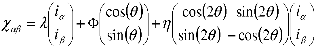
- b) on construit une modélisation d'état du flux magnétique χαβ total circulant dans ladite machine électrique, ledit flux magnétique χαβ étant fonction de la position dudit rotor ;
- c) on construit un observateur d'état des courants x̂ et de la vitesse ω̂ dudit rotor au moyen de ladite modélisation d'état du flux magnétique χαβ et desdits courants im et desdites tensions um mesurés ; et
- d) on détermine ladite position θ̂ du rotor au moyen dudit observateur d'état de la vitesse ω̂ et de ladite tension imposée uimp .
- a) imposing a voltage u imp on said phases of said electric machine;
- b) a state modeling of the total magnetic flux χ αβ circulating in said electric machine, said magnetic flux χ αβ being a function of the position of said rotor;
- c) constructing a state observer of the currents x and the speed ω of said rotor by means of said magnetic flux state modeling χ αβ and said currents i m and said measured voltages u m ; and
- d) determining said position θ of the rotor by means of said speed state observer ω and said imposed voltage u imp .
Selon l'invention, le procédé est appliqué pour une vitesse de rotation du rotor inférieure ou sensiblement égale à 100 tr/min.According to the invention, the method is applied for a rotational speed of the rotor which is less than or substantially equal to 100 rpm.
Avantageusement, ladite tension imposée uimp possède une amplitude Uc supérieure à la tension de commande de ladite machine électrique, et une fréquence fc élevée, supérieure à la fréquence de commande de ladite machine électrique.Advantageously, said imposed voltage u imp has an amplitude U c greater than the control voltage of said electric machine, and a high frequency f c , greater than the control frequency of said electric machine.
De manière avantageuse, ladite amplitude Uc vaut sensiblement 10 V et ladite fréquence fc vaut sensiblement 1 kHz.Advantageously, said amplitude U c is substantially 10 V and said frequency f c is substantially 1 kHz.
De préférence, la tension imposée uimp dans le plan complexe s'écrit par une formule du type : uimp = Ucejθ
Selon un mode de réalisation de l'invention, on construit ladite modélisation d'état du flux magnétique χαβ total circulant dans la machine électrique est obtenue les étapes suivantes :
- i) on détermine les tensions u αβ et courants i αβ dans le repère de Concordia par transformation des tensions um et courants im mesurés ;
- ii) on détermine ledit la dynamique du flux magnétique χαβ par une équation du type : χ̇αβ = -Riαβ + uαβ avec R la résistance des enroulements de ladite machine électrique.
- i) the voltages u αβ and currents i αβ are determined in the Concordia coordinate system by transforming the measured voltages u m and currents i m ;
- ii) said dynamics of the magnetic flux χ αβ are determined by an equation of the following type: χ̇ αβ = -Ri αβ + u αβ with R the resistance of the windings of said electric machine.
De manière avantageuse, on construit lesdits observateurs d'état des courants et de la vitesse du rotor au moyen des étapes suivantes :
- i) on détermine une représentation d'état du courant i αβ à partir de ladite modélisation d'état dudit flux magnétique χαβ par une formule du type :


- ii) on transforme ladite représentation d'état dans le plan complexe en posant x = i α + ji β et u = u α + ju β avec j le nombre complexe ; et
- iii) on détermine lesdits observateurs d'états du courant et de la vitesse du rotor par des équations du type :


En outre, on peut déterminer la position θ̂ dudit rotor au moyen des étapes suivantes :- i) on détermine un coefficient ĉ 2 à partir dudit observateur d'état de la vitesse ω̂ et de ladite tension imposée uimp au moyen d'une équation du type :
-


-
- ii) on détermine ladite position θ̂ dudit rotor au moyen du coefficient ĉ 2 et de courants x mesurés à partir d'une équation du type :
-

-
- i) on détermine un coefficient ĉ 2 à partir dudit observateur d'état de la vitesse ω̂ et de ladite tension imposée uimp au moyen d'une équation du type :
- i) determining a state representation of the current i αβ from said state modeling of said magnetic flux χ αβ by a formula of the type:
- ii) transforming said state representation in the complex plane by setting x = i α + ji β and u = u α + ju β with j the complex number; and
- iii) said observers of states of the current and of the rotor speed are determined by equations of the type:
In addition, the position θ of said rotor can be determined by means of the following steps:- i) determining a coefficient ĉ 2 from said speed state observer ω and said imposed voltage u imp by means of an equation of the type:
-
-
- ii) determining said position θ of said rotor by means of the coefficient ĉ 2 and currents x measured from an equation of the type:
-
-
- i) determining a coefficient ĉ 2 from said speed state observer ω and said imposed voltage u imp by means of an equation of the type:
De plus, l'invention concerne un procédé de commande d'une machine électrique synchrone, pour lequel réalise les étapes suivantes :
- on détermine la position θ̂ et la vitesse ω̂ du rotor de ladite machine électrique au moyen du procédé selon le procédé tel que décrit ci-dessus ; et
- on commande le couple de ladite machine synchrone en fonction de la position et de la vitesse déterminées.
- the position θ and the speed ω of the rotor of said electric machine are determined by means of the method according to the method as described above; and
- the torque of said synchronous machine is controlled according to the determined position and speed.
L'invention concerne également un système de commande d'une machine électrique synchrone, adapté à appliquer le procédé de commande tel que décrit précédemment.The invention also relates to a control system of a synchronous electric machine, adapted to apply the control method as described above.
L'invention concerne aussi un véhicule, notamment véhicule automobile hybride ou électrique, comprenant au moins une machine électrique synchrone, le véhicule comprend en outre un système de commande tel que décrit précédemment.The invention also relates to a vehicle, especially a hybrid or electric motor vehicle, comprising at least one synchronous electric machine, the vehicle further comprises a control system as described above.
D'autres caractéristiques et avantages du procédé selon l'invention, apparaîtront à la lecture de la description ci-après d'exemples non limitatifs de réalisations, en se référant aux figures annexées et décrites ci-après.
- La
figure 1 illustre le contrôle d'une machine électrique synchrone selon l'invention. - La
figure 2 est un logigramme du procédé selon l'invention.
- The
figure 1 illustrates the control of a synchronous electric machine according to the invention. - The
figure 2 is a logic diagram of the method according to the invention.
On rappelle que le procédé et le système selon l'invention sont adaptés à une machine électrique synchrone à pôles saillants. La machine électrique synchrone peut être du type à aimants permanents, à excitation commandé ou à double excitation. Une telle machine est composée d'une partie tournante le rotor, et d'une partie fixe le stator. La partie tournante comprend au moins un aimant (ou un électroaimant). Le stator comprend au moins trois bobines réparties sur trois phases, ces bobines sont alimentées alternativement de manière à générer un champ magnétique apte à faire tourner le rotor. Les bobines sont supportées par une carcasse, également appelé carter.It will be recalled that the method and the system according to the invention are adapted to a synchronous electric machine with salient poles. The synchronous electric machine may be of the permanent magnet, excited excitation or double excitation type. Such a machine is composed of a rotating part the rotor, and a fixed part the stator. The rotating part comprises at least one magnet (or an electromagnet). The stator comprises at least three coils distributed over three phases, these coils are fed alternately so as to generate a magnetic field capable of rotating the rotor. The coils are supported by a carcass, also called a housing.
La
En effet, pour le procédé selon l'invention, on injecte (impose) une tension uimp à la machine électrique. Cette tension possède une fréquence fc élevée de manière à ne pas influencer la commande du moteur ; la fréquence fc de la tension injectée est supérieure à la fréquence du signal de commande de la machine électrique : on peut écrire l'inégalité suivante ω c = 2πfc >> ω. Par exemple, la fréquence fc de la tension injectée est de l'ordre de 1 kHz, la fréquence de rotation du rotor étant à bas régime de l'ordre de 50 Hz. L'injection de signaux rend le modèle observable, y compris à l'arrêt et le rend robuste vis-à-vis du bruit de mesure.Indeed, for the method according to the invention, it injects (imposes) a voltage u imp to the electric machine. This voltage has a high frequency f c so as not to influence the motor control; the frequency f c of the injected voltage is greater than the frequency of the control signal of the electric machine: one can write the following inequality ω c = 2π f c >> ω. For example, the frequency f c of the injected voltage is of the order of 1 kHz, the rotation frequency of the rotor being at low speed of the order of 50 Hz. The injection of signals makes the model observable, including at shutdown and makes it robust against measurement noise.
Par ailleurs, la tension imposée uimp possède une amplitude Uc supérieure à l'amplitude de la tension de commande de la machine électrique. Par exemple, l'amplitude Uc de la tension imposée uimp est de l'ordre de 10 V. Avec une telle fréquence fc et une telle amplitude Uc , la tension imposée uimp n'a pas d'influence sur la commande de la machine électrique et le fonctionnement de la machine électrique n'est pas perturbé, notamment quand la fréquence électrique de fonctionnement de la machine électrique est faible.Moreover, the imposed voltage u imp has an amplitude U c greater than the amplitude of the control voltage of the electric machine. For example, the amplitude U c of the imposed voltage u imp is of the order of 10 V. With such a frequency f c and such an amplitude U c , the imposed voltage u imp has no influence on the control of the electric machine and operation of the electric machine is not disturbed, especially when the electric operating frequency of the electric machine is low.
Au cours de la description, les notations suivantes seront utilisées :
- u : tensions aux bornes des phases de la machine électrique.
- i : courants circulant dans les phases de la machine électrique.
- θ : position du rotor, correspondant à l'angle de rotation du rotor de la machine électrique par rapport au stator.
- ω : vitesse du rotor, correspondant à la vitesse de rotation du rotor de la machine électrique par rapport au stator.
- uimp : tension imposée (injectée) à la machine électrique.
- Uc : amplitude de la tension imposée uimp à la machine électrique. On peut la choisir de l'ordre de 10 V.
- fc : fréquence de la tension imposée uimp à la machine électrique. On peut la choisir de l'ordre de 1 kHz. On rappelle que ω c = 2πfc.
- χ : flux magnétique total vu par la machine électrique.
- R : les résistances des enroulements de la machine électrique, il s'agit d'un paramètre connu (donnée constructeur) ou obtenue expérimentalement.
- Ld : inductance directe de ladite machine électrique, il s'agit d'un paramètre de la machine électrique qui est connu (donnée constructeur ou obtenu expérimentalement).
- Lq : inductance en quadrature de ladite machine électrique, il s'agit d'un paramètre de la machine électrique qui est connu (donnée constructeur ou obtenu expérimentalement).
- Φ : flux magnétique créé par les aimants permanents de ladite machine électrique, il s'agit d'une donnée du constructeur ou pouvant être déterminée expérimentalement.
- x : représentation d'état du courant dans le plan complexe.
- φ : déphasage induit par le filtre continu, ce déphasage, fonction du filtre est connu (dépend de la fréquence fondamentale du signal d'entrée).
- k 1,k 2,g : variables de calibration permettant de gérer la convergence de l'observateur d'état.
- c 1,c 2,a 1 : variables de l'observateur d'état.
- u : voltages at the terminals of the phases of the electric machine.
- i : currents flowing in the phases of the electric machine.
- θ: rotor position, corresponding to the rotation angle of the rotor of the electric machine relative to the stator.
- ω: rotor speed, corresponding to the speed of rotation of the rotor of the electric machine relative to the stator.
- u imp : voltage imposed (injected) on the electric machine.
- U c : amplitude of the imposed voltage u imp to the electric machine. It can be chosen in the order of 10 V.
- f c : frequency of the imposed voltage u imp to the electric machine. It can be chosen in the order of 1 kHz. Remember that ω c = 2π f c .
- χ: total magnetic flux seen by the electric machine.
- R: the resistances of the windings of the electric machine, it is about a known parameter (data manufacturer) or obtained experimentally.
- L d : direct inductance of said electric machine, it is a parameter of the electric machine which is known (data manufacturer or obtained experimentally).
- L q : inductance in quadrature of said electric machine, it is a parameter of the electric machine which is known (data manufacturer or obtained experimentally).
- Φ: magnetic flux created by the permanent magnets of said electrical machine, it is a data of the manufacturer or can be determined experimentally.
- x : state representation of the current in the complex plane.
- φ: phase shift induced by the continuous filter, this phase shift, which is a function of the filter, is known (depends on the fundamental frequency of the input signal).
- k 1 , k 2 , g : calibration variables to manage the convergence of the state observer.
- c 1 , c 2 , a 1 : variables of the state observer.
On pose également :


Ces notations, indexées par la mention -m , représentent les valeurs mesurées. Les valeurs estimées sont indiquées par un accent circonflexe. Les dérivées par rapport au temps sont indiquées par un point. Les notations indexées par la mention -αβ signifient que les grandeurs sont exprimées dans le repère de Concordia. j correspond au nombre complexe. Dans le plan complexe, le conjugué complexe d'une grandeur est indiqué par un segment au dessus de la grandeur considérée.These notations, indexed by the mention - m , represent the measured values. The estimated values are indicated by a circumflex accent. Derivatives with respect to time are indicated by a point. The notations indexed by the mention -αβ mean that the quantities are expressed in the Concordia coordinate system. j is the number complex. In the complex plane, the complex conjugate of a magnitude is indicated by a segment above the magnitude considered.
Le procédé selon l'invention permet de déterminer la position angulaire θ et la vitesse ω d'un rotor d'une machine électrique synchrone, ladite machine électrique étant pourvue de moyens de mesure de tension et de courant des phases de ladite machine électrique. Le procédé selon l'invention est adapté pour déterminer la position θ et la vitesse ω du rotor en particulier à faible régime ou lors de l'arrêt de la machine électrique. On peut considérer les faibles régimes pour des vitesses de rotation de la machine électrique inférieure ou sensiblement égale à 100 tr/min. Pour les autres régimes, les observateurs selon l'invention peuvent être moins précis. Pour palier cet inconvénient, on peut alors utiliser pour ces régimes un autre algorithme, par exemple celui décrit dans la demande de brevet du demandeur dont le numéro de dépôt est
La
- 1) construction d'une modélisation d'état du flux (MOD(χ))
- 2) construction d'observateurs d'état des courants et de la vitesse (OBS( x̂, ω̂))
- 3) estimation de la position au moyen d'un filtrage (FIL)
- 1) construction of a flow state modeling (MOD (χ))
- 2) construction of state observers of currents and velocity (OBS ( x , ω))
- 3) estimation of the position by means of filtering (FIL)
Préalablement à ces étapes, on mesure les courants i et tensions u dans les phases de la machine électrique.Prior to these steps, the currents i and voltages u are measured in the phases of the electric machine.
La machine électrique synchrone est commandée en couple par un contrôle des tensions et des courants d'alimentation des phases de la machine électrique synchrone. Afin de piloter de manière optimale ce moteur il est nécessaire de mesurer les tensions um aux bornes des phases et les courants im y circulant.The synchronous electric machine is controlled in torque by controlling the voltages and the phase supply currents of the synchronous electric machine. In order to optimally control this motor it is necessary to measure the voltages u m at the terminals of the phases and the currents i m circulating there.
A l'aide des informations mesurées voire filtrées, il est possible de reconstruire le flux magnétique total. Il s'agit du flux magnétique vu par la machine électrique, à savoir le flux des aimants, plus le flux du à la réaction magnétique d'induit (c'est-à-dire dû au rotor) pour une machine électrique synchrone à pôles saillants. La reconstruction du flux magnétique est permise par l'utilisation d'une représentation de la dynamique du flux.With the help of measured or filtered information, it is possible to reconstruct the total magnetic flux. This is the magnetic flux seen by the electrical machine, namely the flux of the magnets, plus the flux of the magnetic armature reaction (that is to say, due to the rotor) for a synchronous electric poles machine. protruding. The reconstruction of the magnetic flux is allowed by the use of a representation of the flow dynamics.
Selon un mode de réalisation de l'invention, la modélisation d'état du flux magnétique est construite en réalisant les étapes suivantes :
- i) on détermine les tensions


- ii) la représentation d'état du flux dans le repère de Concordia s'écrit : χ̇αβ = -Riαβ + u αβ. Cette loi découle de la loi de Joule/Faraday.
- i) the tensions are determined
- ii) the state representation of the flow in the Concordia coordinate system is written: χ̇ αβ = -Ri αβ + u αβ . This law derives from the law of Joule / Faraday.
Par ailleurs, 


Lors de cette étape, on construit les observateurs d'état des courants et de la vitesse au moyen de la modélisation d'état du flux déterminé à l'étape précédente ainsi que des mesures de tensions et de courants. En automatique et en théorie de l'information, un observateur d'état est une extension d'un modèle représenté sous forme de représentation d'état. Lorsque l'état d'un système n'est pas mesurable, on construit un observateur qui permet de reconstruire l'état à partir d'un modèle du système dynamique et des mesures d'autres grandeurs (im ,um ).During this step, the state observers of the currents and the velocity are constructed by means of the flow state modeling determined in the previous step as well as measurements of voltages and currents. In automatic and information theory, a state observer is an extension of a model represented as a state representation. When the state of a system is not measurable, we construct an observer that allows us to reconstruct the state from a model of the dynamic system and measurements of other quantities ( i m , u m ).
Selon un mode de réalisation de l'invention, on construit lesdits observateurs d'état des courants et de la vitesse du rotor en mettant en oeuvre les étapes suivantes :
- i)on détermine une représentation d'état du courant i αβ à partir de la représentation d'état du flux magnétique χαβ et de l'expression du flux magnétique par une formule du type :


- ii) on transforme la représentation d'état dans le plan complexe en posant x = ia + jiβ et u = u a + ju β avec j le nombre complexe, le modèle équivalent peut prendre alors la forme suivante : ẋ = α·x+β·ej2θ·
x +γ·ejθ +δ·u+ε·e j2θ·u avec
- iii) étant donné que le modèle étudié est un système périodique, la solution des équations différentielles peuvent être exprimées sous la forme suivante : x(t) = a 1·e jθ + c 1 · e jθ c + c 2 · e j(2θ-θ c ) avec


- i) determining a state representation of the current i αβ from the state representation of the magnetic flux χ αβ and the expression of the magnetic flux by a formula of the type:
- ii) we transform the state representation in the complex plane by putting x = i a + ji β and u = u a + ju β with j the complex number, the equivalent model can then take the following form: ẋ = α · x + β · e j2θ ·
x + γ · e j θ + δ · u + ε · e j2 θ ·u with - iii) since the studied model is a periodic system, the solution of the differential equations can be expressed in the following form: x ( t ) = a 1 · e j θ + c 1 · e j θ c + c 2 · e j (2θ-θ c ) with
Lors de cette étape, on détermine la position du rotor au moyen de l'observateur d'état de la vitesse de rotation, du courant mesuré ainsi qu'à partir de la tension imposée.During this step, the position of the rotor is determined by means of the rotational speed state observer, the measured current as well as from the imposed voltage.
Selon un mode de réalisation de l'invention, on utilise l'estimation de la vitesse ω̂ pour déterminer les paramètres a 1,c 1 ,c 2. En régime stabilisé, on obtient donc des équations du 
![]()

![]()
A partir de ce système, on peut déterminer le paramètre c 2.From this system, the parameter c 2 can be determined.
L'étape finale pour obtenir l'estimation de la position du rotor consiste à filtrer les courants mesurés (et non les courants estimés) après les avoir multipliés par le terme e jθ c , ainsi on forme un filtre passe-bande, filtrant les hautes fréquences, par conséquent filtrant les fréquences fc engendrées par la tension imposée. Dans ces conditions la sortie du filtre peut s'écrire : [ejθ![]()
![]()
Le procédé selon l'invention peut être combiné avec le procédé décrit dans la demande de brevet du demandeur dont le numéro de dépôt est
Toutes les étapes du procédé sont exécutées par des moyens informatiques, notamment par un contrôleur de la machine électrique. Ainsi, on peut déterminer en temps réel la position et la vitesse du rotor. En effet, un des avantages du procédé selon l'invention est qu'il est facile à implémenter en ligne et donc on pourra facilement l'intégrer dans un calculateur de véhicule électrique / hybride.All the steps of the method are executed by computer means, in particular by a controller of the electric machine. Thus, the position and speed of the rotor can be determined in real time. Indeed, one of the advantages of the method according to the invention is that it is easy to implement online and therefore it can easily be integrated into an electric vehicle / hybrid calculator.
L'invention concerne également un procédé de commande d'une machine électrique synchrone, pour lequel on réalise les étapes suivantes :
- on détermine la position θ et la vitesse ω du rotor de ladite machine électrique à l'aide du procédé décrit ci-dessus, en injectant la tension imposée uimp telle que décrite ci-dessus ; et
- on contrôle le couple de ladite machine synchrone en fonction de la position θ et de la vitesse déterminée ω. Pour cette étape, on peut utiliser tout moyen classique de contrôle vectoriel du couple de la machine électrique, qui prend en en compte en plus de la position et de la vitesse du rotor, les tensions et courants mesurés. La prise en compte de la position et de la vitesse pour la commande de la machine électrique permet de déterminer précisément le comportement de la machine électrique, ce qui permet de réaliser une commande adaptée à son fonctionnement.
- the position θ and the speed ω of the rotor of said electric machine are determined by means of the method described above, by injecting the imposed tension u imp as described above; and
- the torque of said synchronous machine is controlled as a function of the position θ and the determined speed ω. For this step, it is possible to use any conventional vector control means of the torque of the electric machine, which takes into account in addition to the position and speed of the rotor, the measured voltages and currents. Taking into account the position and the speed for the control of the electrical machine makes it possible to precisely determine the behavior of the electric machine, which makes it possible to carry out a command adapted to its operation.
En outre, l'invention concerne un système de commande d'une machine électrique synchrone adapté à appliquer le procédé tel que décrit ci-dessus. Un tel système de commande (1) de machine électrique (4) est illustré en
Ce système de commande, peut être utilisé pour une machine électrique synchrone embarquée à bord d'un véhicule, notamment à bord d'un véhicule automobile électrique ou hybride. Toutefois, le système de commande décrit n'est pas limité à cette application et convient pour toutes les applications des machines électriques synchrones.This control system can be used for a synchronous electrical machine on board a vehicle, especially in an electric or hybrid motor vehicle. However, the described control system is not limited to this application and is suitable for all applications of synchronous electrical machines.
Claims (11)


Applications Claiming Priority (1)
| Application Number | Priority Date | Filing Date | Title |
|---|---|---|---|
| FR1354520A FR3006126B1 (en) | 2013-05-21 | 2013-05-21 | METHOD FOR DETERMINING THE POSITION AND SPEED OF A ROTOR OF A SYNCHRONOUS ELECTRIC MACHINE USING STATE OBSERVERS |
Publications (2)
| Publication Number | Publication Date |
|---|---|
| EP2806555A1 true EP2806555A1 (en) | 2014-11-26 |
| EP2806555B1 EP2806555B1 (en) | 2023-07-12 |
Family
ID=48782502
Family Applications (1)
| Application Number | Title | Priority Date | Filing Date |
|---|---|---|---|
| EP14305690.1A Active EP2806555B1 (en) | 2013-05-21 | 2014-05-12 | Method for determining the position and speed of a rotor of a synchronous electric machine by means of status observers |
Country Status (5)
| Country | Link |
|---|---|
| US (1) | US9441943B2 (en) |
| EP (1) | EP2806555B1 (en) |
| JP (1) | JP6557452B2 (en) |
| CN (1) | CN104184381B (en) |
| FR (1) | FR3006126B1 (en) |
Families Citing this family (5)
| Publication number | Priority date | Publication date | Assignee | Title |
|---|---|---|---|---|
| FR3053183B1 (en) * | 2016-06-22 | 2018-06-22 | Renault S.A.S | METHOD FOR ESTIMATING THE POSITION AND SPEED OF THE ROTOR OF AN ALTERNATING CURRENT MACHINE FOR A MOTOR VEHICLE AND CORRESPONDING SYSTEM |
| CN107782344B (en) * | 2016-08-31 | 2020-07-17 | 青岛农业大学 | Rotary transformer signal converter suitable for variable speed condition |
| CN107453348A (en) * | 2017-06-19 | 2017-12-08 | 西安电子科技大学 | More electric aircraft mains frequency method of estimation and device, aircraft electrical system, aircraft |
| DE102018210816A1 (en) * | 2018-06-30 | 2020-01-02 | Robert Bosch Gmbh | Sensor device for an electrical machine, method for operating a sensor device |
| DE102019211800B4 (en) | 2019-08-06 | 2022-12-15 | Conti Temic Microelectronic Gmbh | Method and device for determining the speed and the angle of rotation of a motor shaft of a mechanically commutated DC motor |
Citations (9)
| Publication number | Priority date | Publication date | Assignee | Title |
|---|---|---|---|---|
| FR1103994A (en) | 1954-07-12 | 1955-11-15 | Composition intended for use as a coating | |
| GB1214331A (en) | 1967-01-12 | 1970-12-02 | Ckd Praha | Improvements in or relating to circuits for controlling converters feeding synchronous machines |
| FR2623033A1 (en) | 1987-10-27 | 1989-05-12 | Gen Electric | ROTOR POSITION ESTIMATOR FOR SWITCHED RELUCTANCE MOTOR |
| US5296793A (en) * | 1986-11-05 | 1994-03-22 | Massachusetts Institute Of Technology | State observer for synchronous motors |
| FR2781318A1 (en) * | 1998-07-17 | 2000-01-21 | Bien Air | Control unit for brushless electric motor, |
| EP1492224A1 (en) * | 2002-04-02 | 2004-12-29 | Kabushiki Kaisha Yaskawa Denki | Sensorless controller of ac motor and control method |
| EP1959553A1 (en) * | 2007-02-15 | 2008-08-20 | Sanyo Electric Co., Ltd. | Motor control device |
| US20100237817A1 (en) | 2009-03-23 | 2010-09-23 | Jingbo Liu | Method and Apparatus for Estimating Rotor Position in a Sensorless Synchronous Motor |
| WO2013093223A2 (en) * | 2011-12-20 | 2013-06-27 | IFP Energies Nouvelles | Method for determining the position and the speed of a rotor of a synchronous electric machine |
Family Cites Families (8)
| Publication number | Priority date | Publication date | Assignee | Title |
|---|---|---|---|---|
| US4296793A (en) * | 1977-09-22 | 1981-10-27 | Yasinsky Konstantin K | Refractory suspension for making foundry moulds |
| US5708346A (en) * | 1994-01-10 | 1998-01-13 | Sulzer Electronics Ag | Method and control apparatus for controlling an AC-machine |
| US6137258A (en) * | 1998-10-26 | 2000-10-24 | General Electric Company | System for speed-sensorless control of an induction machine |
| JP4644010B2 (en) * | 2005-02-14 | 2011-03-02 | 日本電産株式会社 | Vector control method and apparatus for synchronous reluctance motor |
| JP4972135B2 (en) * | 2005-08-26 | 2012-07-11 | 三洋電機株式会社 | Motor control device |
| ATE445930T1 (en) * | 2006-06-15 | 2009-10-15 | Abb Oy | METHOD AND SYSTEM RELATED TO PERMANENT MAGNETIC SYNCHRONOUS MACHINES |
| US9106177B2 (en) * | 2012-01-05 | 2015-08-11 | GM Global Technology Operations LLC | Method and system for sensorless control of an electric motor |
| WO2014057575A1 (en) * | 2012-10-12 | 2014-04-17 | 三菱電機株式会社 | Synchronous machine control device |
-
2013
- 2013-05-21 FR FR1354520A patent/FR3006126B1/en active Active
-
2014
- 2014-05-12 EP EP14305690.1A patent/EP2806555B1/en active Active
- 2014-05-20 CN CN201410284799.1A patent/CN104184381B/en active Active
- 2014-05-21 JP JP2014104882A patent/JP6557452B2/en not_active Expired - Fee Related
- 2014-05-21 US US14/283,330 patent/US9441943B2/en active Active
Patent Citations (10)
| Publication number | Priority date | Publication date | Assignee | Title |
|---|---|---|---|---|
| FR1103994A (en) | 1954-07-12 | 1955-11-15 | Composition intended for use as a coating | |
| GB1214331A (en) | 1967-01-12 | 1970-12-02 | Ckd Praha | Improvements in or relating to circuits for controlling converters feeding synchronous machines |
| US5296793A (en) * | 1986-11-05 | 1994-03-22 | Massachusetts Institute Of Technology | State observer for synchronous motors |
| FR2623033A1 (en) | 1987-10-27 | 1989-05-12 | Gen Electric | ROTOR POSITION ESTIMATOR FOR SWITCHED RELUCTANCE MOTOR |
| FR2781318A1 (en) * | 1998-07-17 | 2000-01-21 | Bien Air | Control unit for brushless electric motor, |
| FR2781318B1 (en) | 1998-07-17 | 2000-09-22 | Bien Air | ELECTRIC MOTOR CONTROL DEVICE |
| EP1492224A1 (en) * | 2002-04-02 | 2004-12-29 | Kabushiki Kaisha Yaskawa Denki | Sensorless controller of ac motor and control method |
| EP1959553A1 (en) * | 2007-02-15 | 2008-08-20 | Sanyo Electric Co., Ltd. | Motor control device |
| US20100237817A1 (en) | 2009-03-23 | 2010-09-23 | Jingbo Liu | Method and Apparatus for Estimating Rotor Position in a Sensorless Synchronous Motor |
| WO2013093223A2 (en) * | 2011-12-20 | 2013-06-27 | IFP Energies Nouvelles | Method for determining the position and the speed of a rotor of a synchronous electric machine |
Non-Patent Citations (1)
| Title |
|---|
| ALFIO CONSOLI ET AL: "Low- and Zero-Speed Sensorless Control of Synchronous Reluctance Motors", IEEE TRANSACTIONS ON INDUSTRY APPLICATIONS, IEEE SERVICE CENTER, PISCATAWAY, NJ, US, vol. 35, no. 5, 1 October 1999 (1999-10-01), XP011022630, ISSN: 0093-9994 * |
Also Published As
| Publication number | Publication date |
|---|---|
| EP2806555B1 (en) | 2023-07-12 |
| US9441943B2 (en) | 2016-09-13 |
| JP6557452B2 (en) | 2019-08-07 |
| FR3006126A1 (en) | 2014-11-28 |
| JP2014230485A (en) | 2014-12-08 |
| CN104184381A (en) | 2014-12-03 |
| US20140346990A1 (en) | 2014-11-27 |
| CN104184381B (en) | 2020-11-10 |
| FR3006126B1 (en) | 2015-05-15 |
Similar Documents
| Publication | Publication Date | Title |
|---|---|---|
| EP2806556B1 (en) | Method and system for determining internal temperatures of a synchronous electric machine by means of status observers | |
| EP2806555B1 (en) | Method for determining the position and speed of a rotor of a synchronous electric machine by means of status observers | |
| EP2246973B1 (en) | Method for determining the position of the flux vector of a motor | |
| EP2845311B1 (en) | Method for determining the angular offset between the rotor and the stator of an electrical machine of a motor vehicle | |
| EP2684289B1 (en) | Control method implemented in a power converter and intended for identifying parameters linked to the magnetic saturation of an electric motor | |
| WO2013093223A2 (en) | Method for determining the position and the speed of a rotor of a synchronous electric machine | |
| FR3005539A1 (en) | METHOD FOR ESTIMATING THE ANGULAR POSITION OF THE ROTOR OF A POLYPHASE ELECTRIC ROTARY MACHINE AND APPLICATION TO THE CONTROL OF A POLYPHASE-INVERTER FOR SUCH A MACHINE | |
| EP3221958B1 (en) | Method for controlling a synchronous electric machine with a wound rotor | |
| EP2870018B1 (en) | Method for controlling a power train and corresponding system | |
| EP3138193A2 (en) | Method for estimating the electrical angle of an asynchronous electric machine for a motor vehicle | |
| EP3012962A1 (en) | Method for controlling a three-phase synchronous electric machine with a wound rotor | |
| WO2020020924A1 (en) | Method for checking the setting of an angular position sensor of a rotor for a vehicle | |
| EP3928426B1 (en) | Method for estimating the torque of a synchronous electric machine | |
| WO2020058131A1 (en) | Method for determining the magnetic flux of an electrical machine | |
| EP2783461B1 (en) | Method for controlling a power train and corresponding control system | |
| FR3028362A1 (en) | METHOD AND SYSTEM FOR CONTROLLING A SYNCHRONOUS ELECTRIC MACHINE WITH PERMANENT MAGNETS. | |
| WO2015136173A2 (en) | Method and system for controlling a triple-phase electrical machine of a motor vehicle | |
| EP2992602B1 (en) | Method of verifying the operation of a motor propulsion plant fitted to an automotive vehicle and corresponding system | |
| WO2023062167A1 (en) | Method for estimating the position and speed of the rotor of a permanent-magnet synchronous electric motor | |
| WO2015121049A2 (en) | Method of controlling a permanent-magnet electric machine optimizing the joule losses | |
| EP3739350A1 (en) | Electronic device and method for estimating rotor resistance of an electric machine | |
| FR3038164A1 (en) | CONTROL OF SYNCHRONOUS ROTOR COIL ELECTRIC MACHINE |
Legal Events
| Date | Code | Title | Description |
|---|---|---|---|
| PUAI | Public reference made under article 153(3) epc to a published international application that has entered the european phase |
Free format text: ORIGINAL CODE: 0009012 |
|
| 17P | Request for examination filed |
Effective date: 20140512 |
|
| AK | Designated contracting states |
Kind code of ref document: A1 Designated state(s): AL AT BE BG CH CY CZ DE DK EE ES FI FR GB GR HR HU IE IS IT LI LT LU LV MC MK MT NL NO PL PT RO RS SE SI SK SM TR |
|
| AX | Request for extension of the european patent |
Extension state: BA ME |
|
| R17P | Request for examination filed (corrected) |
Effective date: 20150526 |
|
| RBV | Designated contracting states (corrected) |
Designated state(s): AL AT BE BG CH CY CZ DE DK EE ES FI FR GB GR HR HU IE IS IT LI LT LU LV MC MK MT NL NO PL PT RO RS SE SI SK SM TR |
|
| STAA | Information on the status of an ep patent application or granted ep patent |
Free format text: STATUS: EXAMINATION IS IN PROGRESS |
|
| 17Q | First examination report despatched |
Effective date: 20170919 |
|
| RAP1 | Party data changed (applicant data changed or rights of an application transferred) |
Owner name: IFP ENERGIES NOUVELLES |
|
| STAA | Information on the status of an ep patent application or granted ep patent |
Free format text: STATUS: EXAMINATION IS IN PROGRESS |
|
| REG | Reference to a national code |
Ref document number: 602014087587 Country of ref document: DE Ref country code: DE Ref legal event code: R079 Free format text: PREVIOUS MAIN CLASS: H02P0025080000 Ipc: H02P0021180000 |
|
| RIC1 | Information provided on ipc code assigned before grant |
Ipc: H02P 23/12 20060101ALI20220921BHEP Ipc: H02P 21/18 20160101AFI20220921BHEP |
|
| GRAP | Despatch of communication of intention to grant a patent |
Free format text: ORIGINAL CODE: EPIDOSNIGR1 |
|
| STAA | Information on the status of an ep patent application or granted ep patent |
Free format text: STATUS: GRANT OF PATENT IS INTENDED |
|
| INTG | Intention to grant announced |
Effective date: 20230123 |
|
| GRAS | Grant fee paid |
Free format text: ORIGINAL CODE: EPIDOSNIGR3 |
|
| GRAA | (expected) grant |
Free format text: ORIGINAL CODE: 0009210 |
|
| STAA | Information on the status of an ep patent application or granted ep patent |
Free format text: STATUS: THE PATENT HAS BEEN GRANTED |
|
| AK | Designated contracting states |
Kind code of ref document: B1 Designated state(s): AL AT BE BG CH CY CZ DE DK EE ES FI FR GB GR HR HU IE IS IT LI LT LU LV MC MK MT NL NO PL PT RO RS SE SI SK SM TR |
|
| REG | Reference to a national code |
Ref country code: CH Ref legal event code: EP |
|
| REG | Reference to a national code |
Ref country code: DE Ref legal event code: R096 Ref document number: 602014087587 Country of ref document: DE |
|
| REG | Reference to a national code |
Ref country code: IE Ref legal event code: FG4D Free format text: LANGUAGE OF EP DOCUMENT: FRENCH |
|
| REG | Reference to a national code |
Ref country code: LT Ref legal event code: MG9D |
|
| REG | Reference to a national code |
Ref country code: NL Ref legal event code: MP Effective date: 20230712 |
|
| REG | Reference to a national code |
Ref country code: AT Ref legal event code: MK05 Ref document number: 1588174 Country of ref document: AT Kind code of ref document: T Effective date: 20230712 |
|
| PG25 | Lapsed in a contracting state [announced via postgrant information from national office to epo] |
Ref country code: NL Free format text: LAPSE BECAUSE OF FAILURE TO SUBMIT A TRANSLATION OF THE DESCRIPTION OR TO PAY THE FEE WITHIN THE PRESCRIBED TIME-LIMIT Effective date: 20230712 |
|
| PG25 | Lapsed in a contracting state [announced via postgrant information from national office to epo] |
Ref country code: GR Free format text: LAPSE BECAUSE OF FAILURE TO SUBMIT A TRANSLATION OF THE DESCRIPTION OR TO PAY THE FEE WITHIN THE PRESCRIBED TIME-LIMIT Effective date: 20231013 |
|
| PG25 | Lapsed in a contracting state [announced via postgrant information from national office to epo] |
Ref country code: ES Free format text: LAPSE BECAUSE OF FAILURE TO SUBMIT A TRANSLATION OF THE DESCRIPTION OR TO PAY THE FEE WITHIN THE PRESCRIBED TIME-LIMIT Effective date: 20230712 |
|
| PG25 | Lapsed in a contracting state [announced via postgrant information from national office to epo] |
Ref country code: IS Free format text: LAPSE BECAUSE OF FAILURE TO SUBMIT A TRANSLATION OF THE DESCRIPTION OR TO PAY THE FEE WITHIN THE PRESCRIBED TIME-LIMIT Effective date: 20231112 |
|
| PG25 | Lapsed in a contracting state [announced via postgrant information from national office to epo] |
Ref country code: SE Free format text: LAPSE BECAUSE OF FAILURE TO SUBMIT A TRANSLATION OF THE DESCRIPTION OR TO PAY THE FEE WITHIN THE PRESCRIBED TIME-LIMIT Effective date: 20230712 Ref country code: RS Free format text: LAPSE BECAUSE OF FAILURE TO SUBMIT A TRANSLATION OF THE DESCRIPTION OR TO PAY THE FEE WITHIN THE PRESCRIBED TIME-LIMIT Effective date: 20230712 Ref country code: PT Free format text: LAPSE BECAUSE OF FAILURE TO SUBMIT A TRANSLATION OF THE DESCRIPTION OR TO PAY THE FEE WITHIN THE PRESCRIBED TIME-LIMIT Effective date: 20231113 Ref country code: NO Free format text: LAPSE BECAUSE OF FAILURE TO SUBMIT A TRANSLATION OF THE DESCRIPTION OR TO PAY THE FEE WITHIN THE PRESCRIBED TIME-LIMIT Effective date: 20231012 Ref country code: LV Free format text: LAPSE BECAUSE OF FAILURE TO SUBMIT A TRANSLATION OF THE DESCRIPTION OR TO PAY THE FEE WITHIN THE PRESCRIBED TIME-LIMIT Effective date: 20230712 Ref country code: LT Free format text: LAPSE BECAUSE OF FAILURE TO SUBMIT A TRANSLATION OF THE DESCRIPTION OR TO PAY THE FEE WITHIN THE PRESCRIBED TIME-LIMIT Effective date: 20230712 Ref country code: IS Free format text: LAPSE BECAUSE OF FAILURE TO SUBMIT A TRANSLATION OF THE DESCRIPTION OR TO PAY THE FEE WITHIN THE PRESCRIBED TIME-LIMIT Effective date: 20231112 Ref country code: HR Free format text: LAPSE BECAUSE OF FAILURE TO SUBMIT A TRANSLATION OF THE DESCRIPTION OR TO PAY THE FEE WITHIN THE PRESCRIBED TIME-LIMIT Effective date: 20230712 Ref country code: GR Free format text: LAPSE BECAUSE OF FAILURE TO SUBMIT A TRANSLATION OF THE DESCRIPTION OR TO PAY THE FEE WITHIN THE PRESCRIBED TIME-LIMIT Effective date: 20231013 Ref country code: FI Free format text: LAPSE BECAUSE OF FAILURE TO SUBMIT A TRANSLATION OF THE DESCRIPTION OR TO PAY THE FEE WITHIN THE PRESCRIBED TIME-LIMIT Effective date: 20230712 Ref country code: ES Free format text: LAPSE BECAUSE OF FAILURE TO SUBMIT A TRANSLATION OF THE DESCRIPTION OR TO PAY THE FEE WITHIN THE PRESCRIBED TIME-LIMIT Effective date: 20230712 Ref country code: AT Free format text: LAPSE BECAUSE OF FAILURE TO SUBMIT A TRANSLATION OF THE DESCRIPTION OR TO PAY THE FEE WITHIN THE PRESCRIBED TIME-LIMIT Effective date: 20230712 |
|
| PG25 | Lapsed in a contracting state [announced via postgrant information from national office to epo] |
Ref country code: PL Free format text: LAPSE BECAUSE OF FAILURE TO SUBMIT A TRANSLATION OF THE DESCRIPTION OR TO PAY THE FEE WITHIN THE PRESCRIBED TIME-LIMIT Effective date: 20230712 |