EP1492101B1 - Disque optique doté d'une structure de champ proche à super résolution - Google Patents
Disque optique doté d'une structure de champ proche à super résolution Download PDFInfo
- Publication number
- EP1492101B1 EP1492101B1 EP04253560A EP04253560A EP1492101B1 EP 1492101 B1 EP1492101 B1 EP 1492101B1 EP 04253560 A EP04253560 A EP 04253560A EP 04253560 A EP04253560 A EP 04253560A EP 1492101 B1 EP1492101 B1 EP 1492101B1
- Authority
- EP
- European Patent Office
- Prior art keywords
- optical disc
- phase
- layer
- auxiliary layer
- crystalline material
- Prior art date
- Legal status (The legal status is an assumption and is not a legal conclusion. Google has not performed a legal analysis and makes no representation as to the accuracy of the status listed.)
- Expired - Fee Related
Links
Images


Classifications
-
- G—PHYSICS
- G11—INFORMATION STORAGE
- G11B—INFORMATION STORAGE BASED ON RELATIVE MOVEMENT BETWEEN RECORD CARRIER AND TRANSDUCER
- G11B7/00—Recording or reproducing by optical means, e.g. recording using a thermal beam of optical radiation by modifying optical properties or the physical structure, reproducing using an optical beam at lower power by sensing optical properties; Record carriers therefor
- G11B7/24—Record carriers characterised by shape, structure or physical properties, or by the selection of the material
- G11B7/241—Record carriers characterised by shape, structure or physical properties, or by the selection of the material characterised by the selection of the material
- G11B7/242—Record carriers characterised by shape, structure or physical properties, or by the selection of the material characterised by the selection of the material of recording layers
- G11B7/243—Record carriers characterised by shape, structure or physical properties, or by the selection of the material characterised by the selection of the material of recording layers comprising inorganic materials only, e.g. ablative layers
- G11B7/2433—Metals or elements of groups 13, 14, 15 or 16 of the Periodic System, e.g. B, Si, Ge, As, Sb, Bi, Se or Te
-
- G—PHYSICS
- G11—INFORMATION STORAGE
- G11B—INFORMATION STORAGE BASED ON RELATIVE MOVEMENT BETWEEN RECORD CARRIER AND TRANSDUCER
- G11B7/00—Recording or reproducing by optical means, e.g. recording using a thermal beam of optical radiation by modifying optical properties or the physical structure, reproducing using an optical beam at lower power by sensing optical properties; Record carriers therefor
- G11B7/24—Record carriers characterised by shape, structure or physical properties, or by the selection of the material
- G11B7/241—Record carriers characterised by shape, structure or physical properties, or by the selection of the material characterised by the selection of the material
- G11B7/242—Record carriers characterised by shape, structure or physical properties, or by the selection of the material characterised by the selection of the material of recording layers
- G11B7/243—Record carriers characterised by shape, structure or physical properties, or by the selection of the material characterised by the selection of the material of recording layers comprising inorganic materials only, e.g. ablative layers
-
- G—PHYSICS
- G11—INFORMATION STORAGE
- G11B—INFORMATION STORAGE BASED ON RELATIVE MOVEMENT BETWEEN RECORD CARRIER AND TRANSDUCER
- G11B7/00—Recording or reproducing by optical means, e.g. recording using a thermal beam of optical radiation by modifying optical properties or the physical structure, reproducing using an optical beam at lower power by sensing optical properties; Record carriers therefor
- G11B7/24—Record carriers characterised by shape, structure or physical properties, or by the selection of the material
- G11B7/241—Record carriers characterised by shape, structure or physical properties, or by the selection of the material characterised by the selection of the material
- G11B7/252—Record carriers characterised by shape, structure or physical properties, or by the selection of the material characterised by the selection of the material of layers other than recording layers
-
- G—PHYSICS
- G11—INFORMATION STORAGE
- G11B—INFORMATION STORAGE BASED ON RELATIVE MOVEMENT BETWEEN RECORD CARRIER AND TRANSDUCER
- G11B7/00—Recording or reproducing by optical means, e.g. recording using a thermal beam of optical radiation by modifying optical properties or the physical structure, reproducing using an optical beam at lower power by sensing optical properties; Record carriers therefor
- G11B7/24—Record carriers characterised by shape, structure or physical properties, or by the selection of the material
- G11B7/241—Record carriers characterised by shape, structure or physical properties, or by the selection of the material characterised by the selection of the material
- G11B7/242—Record carriers characterised by shape, structure or physical properties, or by the selection of the material characterised by the selection of the material of recording layers
- G11B7/243—Record carriers characterised by shape, structure or physical properties, or by the selection of the material characterised by the selection of the material of recording layers comprising inorganic materials only, e.g. ablative layers
- G11B2007/24302—Metals or metalloids
- G11B2007/24314—Metals or metalloids group 15 elements (e.g. Sb, Bi)
-
- G—PHYSICS
- G11—INFORMATION STORAGE
- G11B—INFORMATION STORAGE BASED ON RELATIVE MOVEMENT BETWEEN RECORD CARRIER AND TRANSDUCER
- G11B7/00—Recording or reproducing by optical means, e.g. recording using a thermal beam of optical radiation by modifying optical properties or the physical structure, reproducing using an optical beam at lower power by sensing optical properties; Record carriers therefor
- G11B7/24—Record carriers characterised by shape, structure or physical properties, or by the selection of the material
- G11B7/241—Record carriers characterised by shape, structure or physical properties, or by the selection of the material characterised by the selection of the material
- G11B7/242—Record carriers characterised by shape, structure or physical properties, or by the selection of the material characterised by the selection of the material of recording layers
- G11B7/243—Record carriers characterised by shape, structure or physical properties, or by the selection of the material characterised by the selection of the material of recording layers comprising inorganic materials only, e.g. ablative layers
- G11B2007/24302—Metals or metalloids
- G11B2007/24316—Metals or metalloids group 16 elements (i.e. chalcogenides, Se, Te)
-
- G—PHYSICS
- G11—INFORMATION STORAGE
- G11B—INFORMATION STORAGE BASED ON RELATIVE MOVEMENT BETWEEN RECORD CARRIER AND TRANSDUCER
- G11B7/00—Recording or reproducing by optical means, e.g. recording using a thermal beam of optical radiation by modifying optical properties or the physical structure, reproducing using an optical beam at lower power by sensing optical properties; Record carriers therefor
- G11B7/24—Record carriers characterised by shape, structure or physical properties, or by the selection of the material
- G11B7/241—Record carriers characterised by shape, structure or physical properties, or by the selection of the material characterised by the selection of the material
- G11B7/252—Record carriers characterised by shape, structure or physical properties, or by the selection of the material characterised by the selection of the material of layers other than recording layers
- G11B7/257—Record carriers characterised by shape, structure or physical properties, or by the selection of the material characterised by the selection of the material of layers other than recording layers of layers having properties involved in recording or reproduction, e.g. optical interference layers or sensitising layers or dielectric layers, which are protecting the recording layers
- G11B2007/25705—Record carriers characterised by shape, structure or physical properties, or by the selection of the material characterised by the selection of the material of layers other than recording layers of layers having properties involved in recording or reproduction, e.g. optical interference layers or sensitising layers or dielectric layers, which are protecting the recording layers consisting essentially of inorganic materials
- G11B2007/25715—Record carriers characterised by shape, structure or physical properties, or by the selection of the material characterised by the selection of the material of layers other than recording layers of layers having properties involved in recording or reproduction, e.g. optical interference layers or sensitising layers or dielectric layers, which are protecting the recording layers consisting essentially of inorganic materials containing oxygen
Definitions
- the present invention relates to an optical disc, and more particularly, to an optical disc incorporating a super-resolution near-field structure (Super-RENS), designed to record and reproduce marks with a size below a resolution limit of a laser beam.
- Super-RENS super-resolution near-field structure
- Optical discs are the most widely used high-density recording media since they require a much smaller recording area per recording unit than magnetic recording media.
- the optical discs are classified into three basic types according to their function: read-only memory (ROM) where recorded information is only read, write-once read-many (WORM) where data can be written once, and rewritable (RW) where data can be fully recorded, erased, and rerecorded.
- ROM read-only memory
- WORM write-once read-many
- RW rewritable
- CD-R compact disc recordable
- a 780 nm recording laser heats a recording layer made of cyanine or phthalocyanine organic dye, the heat causes decomposition of the dye layer and deformation of the surface of a substrate and a reflective layer.
- CD-R media are optical discs used to read a recorded signal at a low power of usually less than 1 mW. With a recording capacity of about 650 MB, they are widely used to write and read various types of data such as data, music, and video.
- DVD digital versatile disc
- DVD-ROM read-only type
- DVD-R write-once type
- DVD-RAM rewritable type
- DVD-R discs While recording on DVD-R discs is accomplished by deforming and decomposing a recording layer by laser radiation emitted from a recording laser, recording on DVD-RAM and DVD-RW media is accomplished by changing optical properties due to phase transition of the recording layer.
- DVD-R media employing organic dye are receiving considerable attention due to their advantages over DVD-RAM in terms of compatibility, price, and capacity.
- Capacity is an issue of great concern to various emerging recordable media (write-once and rewritable).
- Various approaches have been proposed to increase the capacity.
- the recording capacity of an optical disc greatly relies upon how densely and precisely readable small pits are packed into a given area as well as the characteristics of a laser beam that can read those pits.
- a beam emitted from a laser diode and focused through an objective lens cannot be made infinitely smaller due to the effect of diffraction.
- the beam has a finite width called a diffraction limit.
- the wavelength of a light source is ⁇ and a numerical aperture (NA) of an objective lens is NA in a typical optical disc
- NA numerical aperture
- the limit of reading resolution is ⁇ /4NA.
- the current laser technology poses a limitation in providing a shorter wavelength laser.
- the manufacturing costs are too high to manufacture a high NA objective lens.
- a working distance between a pickup and a disc significantly decreases with increasing NA of the objective lens, there is a greater risk of damaging the disc surface and data due to a collision between the pickup and the disc.
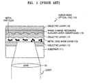
- FIG 1 illustrates a schematic structure of a conventional Super-RENS optical disc 10.
- the conventional Super-RENS optical disc 10 mainly uses a mask layer 13 made from metal oxide such as silver oxide (AgO x ) and palladium oxide (PdO x ).
- a phase-change recording auxiliary layer 15 used in the conventional Super-RENS optical disc 10 is made of a Ge-Sb-Te or Ag-In-Sb-Te based alloy that becomes amorphous immediately after formation of the alloy thin film. Since reflectivity is too low when the phase-change recording auxiliary layer 15 is in the amorphous state, stable focusing or tracking servo cannot be achieved. If reflectivity is increased to achieve stable servo by adjusting the thickness of a multi-layer thin film, the reflectivity becomes too high in the crystalline state to achieve the desired recording sensitivity since a large amount of incident beam is reflected during recording. Thus, when the phase-change recording auxiliary layer 15 made of Ge-Sb-Te or Ag-In-Sb-Te is in amorphous state, the disc must be initialized to crystalline state before recording.
- An initialization process which is one of the most time consuming operations during optical disc production, may result in increased disc price and reduced yield. Furthermore, insufficient initialization may lead to recording of unstable or uneven signals.
- the metal oxide mask layer 13 Upon recording on the disc that has undergone the initialization process, the metal oxide mask layer 13 decomposes to form marks, and at the same time the phase-change recording auxiliary layer 15 is melted and then rapidly quenched into the amorphous state. In this case, to achieve super-resolution, a high power reading beam heats the phase-change recording auxiliary layer 15 to change it from the amorphous state to the crystalline state.
- Defective crystallization of the phase-change recording auxiliary layer 15 also may make a signal uneven or unstable.
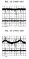
- Figures 2A and 2B show the degradation of an RF signal reproduced when no data is recorded in case of insufficient crystallization. More specifically, Figures 2A and 2B show RF signals reproduced at laser powers of 2 and 3 mW after initialization without recording, respectively. This demonstrates the fact that initialization of the phase-change recording auxiliary layer 15 was incomplete due to its low crystallization rate.
- Figures 3A and 3B show the degradation of an RF signal reproduced after data has been recorded in case of insufficient crystallization.
- Figure 3A shows an RF signal reproduced at a laser power of 2.5 mW immediately after data has been recorded while
- Figure 3B shows an RF signal reproduced at a laser power of 2.5 mW after a predetermined period of time has passed since data was recorded, for example 10 minutes.
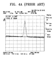
- Figures 4A and 4B illustrate a decrease in C/N ratio due to an increase in noise.
- a noise level is -59.3 dB
- the noise level increases to -56.3 dB although a carrier level remains constant after time for reproduction has passed.
- increased noise level decreases the C/N ratio, which is obtained by subtraction of a noise level from a carrier level.
- An aspect of the present invention provides an optical disc with a super-resolution near-field structure (Super-RENS) designed to allow high quality signal reproduction by eliminating instability and unevenness of a reproduced signal due to insufficient crystallization during reproduction after recording data as well as low manufacturing costs and high production yields.
- Super-RENS super-resolution near-field structure
- an optical disc having multi-layers formed on a substrate on which a beam writes information.
- the optical disc may include one or more mask layers having a super-resolution near-field structure and one or more phase-change recording auxiliary layers, having been deposited as a highly crystalline material.
- the phase-change recording auxiliary layer is in a crystalline state after being formed.
- the highly crystalline material may be antimony telluride (Sb 2 Te 3 ) or Sb.
- An optical disc with a super-resolution near-field structure uses a phase-change recording auxiliary layer in a crystalline state immediately after formation of the thin film.
- Figure 5 shows a Super-RENS optical disc 30 according to an embodiment of the present invention.
- the Super-RENS optical disc 30 includes a substrate 31, a metal oxide mask layer 33 and a phase-change recording auxiliary layer 35 sequentially formed over the substrate 31.
- the Super-RENS optical disc 30 further has dielectric layers 32, 34, and 36 formed between the substrate 31 and the metal oxide mask layer 33, between the metal oxide mask layer 33 and the phase-change auxiliary layer 35, and on the phase-change auxiliary layer 35, respectively.
- the substrate 31 is made from a material providing excellent transparency, impact and heat resistance, and rigidity at a wavelength of a recording laser.
- the material is selected among those that can form the substrate 31 using a commonly manufacturing method such as injection molding. Examples of those materials include polycarbonate, polymetyl metacrylate, epoxy, polyester, and amorphous polyolefin.
- the metal oxide mask layer 33 may be made from silver oxide (AgO x ) or platinum oxide (PtO x ) as in a conventional optical disc, or other metal oxide.
- the phase-change recording auxiliary layer 35 is formed from a highly crystalline material.
- the highly crystalline material refers to a material that can be heated beyond the crystallization temperature into an amorphous phase and then rapidly changed back to a crystalline phase.
- the highly crystalline material may be antimony telluride (Sb 2 Te 3 ) or Sb.
- the phase-change recording auxiliary layer 35 made from Sb 2 Te 3 or Sb is in a crystalline state immediately after its
- the crystallization temperature of Sb 2 Te 3 or Sb is very low, it is possible to rapidly crystallize Sb 2 Te 3 or Sb by the kinetic energy of ions moving quickly from a target toward the Sb 2 Te 3 or Sb thin film during sputtering for thin film formation so that it becomes crystalline immediately after formation of the thin film. As the content of Sb increases, the crystallization rate increases.
- the use of the Sb 2 Te 3 or Sb material in formation of the phase-change recording auxiliary layer 35 eliminates the need for a separate initialization.
- the phase-change recording auxiliary layer 35 undergoes a transition from the amorphous state to the crystalline state more quickly and completely than a conventional layer 15 made from an amorphous material.
- the Super-RENS optical disc 30 makes it possible to minimize the fluctuation of an RF signal during reproduction, thereby allowing uniform stable signal reproduction.
- a conventional Super-RENS disc 10 shown in Figure 1 suffers fluctuation due to slow and incomplete amorphous-to-crystalline phase transition.
- the highly crystalline material of the present invention is not limited to Sb 2 Te 3 or Sb, but may include various other materials allowing quick crystallization.
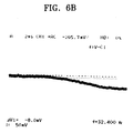
- phase-change recording auxiliary layer 15 undergoes incomplete transition to a crystalline state at high linear velocity of an optical disc 10 due to its low crystallization rate during initialization of the optical disc 10 for crystallization, a reproduced RF signal suffers from a large fluctuation.
- performing initialization at lower linear velocity allows considerably more stable RF signal reproduction according to an aspect of the invention.
- Figures 6A and 6B show RF signals reproduced from initialized Super RENS optical discs at linear velocities of 6 m/s and 3 m/s, respectively. As seen from Figures 6A and 6B, the RF signal reproduced from the initialized optical disc 30 at the linear velocity of 3 m/s is more stable than the RF signal at 6 m/s.
- phase-change recording layer undergoes transition to an amorphous state after data has been recorded.
- a relatively high readout laser power is applied upon reproduction because of characteristics of a Super-RENS optical disc, the amorphous state is changed back to a crystalline state, which aggravates instability in the reproduced signal.
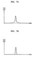
- Figures 7A and 7B illustrate C/N characteristics measured on two Super-RENS optical discs having recording auxiliary layers with different crystallization rates using a spectrum analyzer. More specifically, Figure 7A shows the C/N characteristic of an optical disc using a phase-change recording auxiliary layer containing 60 atomic percent of Sb, while Figure 7B shows the C/N characteristic of an optical disc using a phase-change recording layer containing 70 atomic percent of Sb. Since the higher the content ratio of Sb, the higher the crystallization rate at the same linear velocity, the auxiliary layer containing 70 atomic percent of Sb exhibits better C/N characteristics than the auxiliary layer containing 60 atomic percent.
- phase-change recording auxiliary layer 35 may be used in, for example, rewritable, write-once, and read-only discs. Moreover, the layer 35 can be used in other optical disc types, such as in Bluray or Advanced Optical Discs (AODs). The auxiliary layer 35 can also be applied to single-sided dual-layer, double-sided single-layer, and double-sided dual-layer discs. Furthermore, the Super-RENS optical disc 30 may include a plurality of metal oxide mask layers 33 or a plurality of phase-change recording auxiliary layers 35.
- the Super-RENS optical disc of the present invention has, among others, the following advantages.
- quality of a reproduced signal is improved by removing signal instability and unevenness that may occur due to incomplete crystallization of the phase-change recording auxiliary layer during reproduction of data.
- high data transfer rate is allowed by minimizing a decrease in a C/N response rate due to a phase transition that the phase-change recording auxiliary layer undergoes during reproduction of data.
- no initialization is required so low manufacturing costs and high production yields are allowed since the phase-change recording auxiliary layer is in a crystalline state immediately after its formation.
Claims (27)
- Disque optique ayant plusieurs couches formées sur un substrat (31), sur lequel des informations sont inscrites par un faisceau, comprenant :une ou plusieurs couches de masque (33) ayant une structure de champ proche à super-résolution, etune ou plusieurs couches auxiliaires d'enregistrement à changement de phase (35), chaque couche auxiliaire d'enregistrement (35) ayant été déposée sous la forme d'un matériau fortement cristallin.
- Disque optique selon la revendication 1, dans lequel la couche auxiliaire d'enregistrement à changement de phase (35) est dans un état cristallin.
- Disque optique selon la revendication 1 ou 2, dans lequel le matériau fortement cristallin est le tellurure d'antimoine (Sb2Te3) ou le Sb.
- Disque optique selon la revendication 1, 2 ou 3, dans lequel la couche auxiliaire d'enregistrement à changement de phase (35) passe d'une phase amorphe à une phase cristalline.
- Disque optique selon la revendication 3, dans lequel le Sb2Te3 ou le Sb sont cristallisés par l'énergie cinétique d'ions se déplaçant depuis une cible vers le Sb2Te3 ou le Sb pendant une formation de couche mince.
- Disque optique selon la revendication 3, dans lequel le matériau fortement cristallin élimine l'initialisation du disque optique.
- Disque optique selon l'une quelconque des revendications précédentes, dans lequel la fluctuation d'un signal RF pendant la lecture des données est minimisée.
- Disque optique selon l'une quelconque des revendications précédentes, dans lequel la couche auxiliaire à changement de phase (35) est réinscriptible.
- Disque optique selon l'une quelconque des revendications précédentes, dans lequel la couche auxiliaire à changement de phase (35) est appliquée sur des disques optiques à double couche sur une face, à simple couche sur deux faces et à double couche sur deux faces.
- Disque optique selon l'une quelconque des revendications précédentes, dans lequel le matériau fortement cristallin contient plus de 60% en atomes de Sb.
- Disque optique comprenant :un substrat (31),une couche de masque en oxyde métallique (33), formée sur le substrat (31);une couche auxiliaire d'enregistrement à changement de phase (35) formée sur la couche de masque en oxyde métallique (33), etdes couches diélectriques (32, 34), formées entre le substrat (31), la couche de masque en oxyde métallique (33), et la couche auxiliaire d'enregistrement à changement de phase (35), la couche auxiliaire à changement de phase (35) ayant été déposée sous la forme d'un matériau fortement cristallin.
- Disque optique selon la revendication 11, dans lequel le matériau fortement cristallin est le tellurure d'antimoine (Sb2Te3) ou le Sb.
- Disque optique selon la revendication 11 ou 12, dans lequel la couche auxiliaire d'enregistrement à changement de phase (35) est chauffée au-delà d'une température de cristallisation en une phase amorphe, puis est ramenée à une phase cristalline.
- Disque optique selon la revendication 12 ou 13, dans lequel le Sb2Te3 ou le Sb sont cristallisés par l'énergie cinétique d'ions se déplaçant depuis une cible vers le Sb2Te3 ou le Sb pendant une formation de couche mince.
- Disque optique selon la revendication 12, 13 ou 14, dans lequel le matériau fortement cristallin élimine la nécessité d'une initialisation du disque optique.
- Disque optique selon l'une quelconque des revendications 11 à 15, dans lequel la fluctuation d'un signal RF pendant la lecture des données est minimisée.
- Disque optique selon l'une quelconque des revendications 11 à 16, dans lequel le disque est un disque réinscriptible.
- Disque optique selon l'une quelconque des revendications 11 à 17, dans lequel le disque est un disque à double couche sur une face, à simple couche sur deux faces et à double couche sur deux faces.
- Disque optique selon l'une quelconque des revendications 11 à 18, dans lequel le matériau fortement cristallin contient plus de 60% en atomes de Sb.
- Procédé de formation d'un disque optique, le procédé comprenant :la formation d'une couche de masque en oxyde métallique (33) sur un substrat (31) ;la formation d'une couche auxiliaire d'enregistrement à changement de phase (35) sur la couche de masque en oxyde métallique (33), etla formation de couches diélectriques (32, 34), entre le substrat (31) et la couche de masque en oxyde métallique (33), entre la couche de masque en oxyde métallique (33) et la couche auxiliaire à changement de phase (35), et sur la couche auxiliaire à changement de phase (35), la couche auxiliaire d'enregistrement à changement de phase (35) ayant été déposée sous la forme d'un matériau fortement cristallin.
- Procédé selon la revendication 20, dans lequel la couche auxiliaire d'enregistrement à changement de phase (35) est dans un état fortement cristallin après avoir été formée.
- Procédé selon la revendication 20 ou 21, dans lequel le matériau fortement cristallin est le tellurure d'antimoine (Sb2Te3) ou le Sb.
- Procédé selon la revendication 20, 21 ou 22, dans lequel la couche auxiliaire d'enregistrement à changement de phase (35) est chauffée au-delà d'une température de cristallisation en une phase amorphe, puis est ramenée à une phase cristalline.
- Procédé selon la revendication 22, dans lequel le Sb2Te3 ou le Sb sont cristallisés par l'énergie cinétique d'ions se déplaçant depuis une cible vers le Sb2Te3 ou le Sb pendant une formation de couche mince.
- Procédé selon la revendication 22, dans lequel l'utilisation du matériau fortement cristallin dans la formation de la couche auxiliaire d'enregistrement à changement de phase (35) élimine la nécessité d'une initialisation du disque optique.
- Procédé selon l'une quelconque des revendications 20 à 25, dans lequel la fluctuation d'un signal RF pendant la lecture des données est minimisée.
- Procédé selon l'une quelconque des revendications 20 à 26, dans lequel le matériau fortement cristallin contient plus de 60% en atomes de Sb.
Applications Claiming Priority (2)
| Application Number | Priority Date | Filing Date | Title |
|---|---|---|---|
| KR1020030040687A KR20050000108A (ko) | 2003-06-23 | 2003-06-23 | 초해상 근접장 구조를 가지는 광디스크 |
| KR2003040687 | 2003-06-23 |
Publications (3)
| Publication Number | Publication Date |
|---|---|
| EP1492101A2 EP1492101A2 (fr) | 2004-12-29 |
| EP1492101A3 EP1492101A3 (fr) | 2005-03-02 |
| EP1492101B1 true EP1492101B1 (fr) | 2006-08-30 |
Family
ID=33411775
Family Applications (1)
| Application Number | Title | Priority Date | Filing Date |
|---|---|---|---|
| EP04253560A Expired - Fee Related EP1492101B1 (fr) | 2003-06-23 | 2004-06-15 | Disque optique doté d'une structure de champ proche à super résolution |
Country Status (7)
| Country | Link |
|---|---|
| US (1) | US20040257968A1 (fr) |
| EP (1) | EP1492101B1 (fr) |
| JP (1) | JP2005018974A (fr) |
| KR (1) | KR20050000108A (fr) |
| CN (1) | CN1573995A (fr) |
| DE (1) | DE602004002150D1 (fr) |
| TW (1) | TW200501151A (fr) |
Families Citing this family (27)
| Publication number | Priority date | Publication date | Assignee | Title |
|---|---|---|---|---|
| JP3836722B2 (ja) * | 2001-12-28 | 2006-10-25 | 株式会社日立製作所 | 非線形光学薄膜とそれを用いた光情報記録媒体及び光スイッチ |
| US6896946B2 (en) * | 2002-06-06 | 2005-05-24 | Ritek Corporation | Initiation-free super-resolution optical medium |
| KR20050029765A (ko) * | 2003-09-22 | 2005-03-28 | 삼성전자주식회사 | 고밀도 재생전용 광디스크 및 그 제조방법 |
| KR20050032689A (ko) * | 2003-10-02 | 2005-04-08 | 삼성전자주식회사 | 고밀도 재생전용 광디스크 |
| US7232598B2 (en) * | 2003-10-22 | 2007-06-19 | Lg Electronics Inc. | Super resolution optical disc |
| KR20050052606A (ko) * | 2003-11-28 | 2005-06-03 | 삼성전자주식회사 | 정보저장매체, 이에 기록된 정보재생방법 및 장치 |
| KR20050053132A (ko) * | 2003-12-02 | 2005-06-08 | 삼성전자주식회사 | 초해상 정보 저장 매체 |
| KR20050054658A (ko) * | 2003-12-05 | 2005-06-10 | 삼성전자주식회사 | 초해상 정보 저장 매체 및 정보저장매체의 열화 방지 방법 |
| KR100601700B1 (ko) * | 2004-08-25 | 2006-07-14 | 삼성전자주식회사 | 초해상 정보 저장매체, 데이터 재생 방법 및 데이터 기록및/또는 재생 장치 |
| JP4209416B2 (ja) * | 2005-09-29 | 2009-01-14 | シャープ株式会社 | 光情報記録媒体、及び光情報記録媒体再生装置 |
| EP1968048A1 (fr) * | 2007-03-08 | 2008-09-10 | Deutsche Thomson OHG | Support de stockage optique et appareil de lecture des données respectives |
| EP2009626A1 (fr) | 2007-06-29 | 2008-12-31 | Deutsche Thomson OHG | Appareil comprenant une unité de capture fournissant trois faisceaux de données de lecture depuis ou écrivant des données sur un support de stockage optique et support de stockage optique correspondant |
| CN101354900B (zh) * | 2007-07-27 | 2011-11-23 | 国家纳米科学中心 | 一种具有超分辨近场结构的只读光盘 |
| CN101981621B (zh) * | 2008-02-13 | 2012-10-31 | 汤姆森特许公司 | 光学存储介质、制作方法以及读取相应数据的装置 |
| EP2109104A1 (fr) | 2008-04-09 | 2009-10-14 | Deutsche Thomson OHG | Support de stockage optique comportant deux couches de semi-conducteurs en tant que couches de masque |
| JP2010020879A (ja) * | 2008-06-11 | 2010-01-28 | Sony Corp | 信号検出装置及び信号検出方法 |
| EP2196993A1 (fr) | 2008-12-02 | 2010-06-16 | Thomson Licensing | Support de stockage optique comprenant deux couches non linéaires |
| EP2200027A1 (fr) | 2008-12-22 | 2010-06-23 | Thomson Licensing | Disque optique, procédé de maîtrise et appareil pour la lecture des données correspondantes |
| EP2315204A1 (fr) | 2009-10-21 | 2011-04-27 | Thomson Licensing | Support d'enregistrement optique et procédé et appareil pour lire un tel support |
| EP2320418A1 (fr) | 2009-10-30 | 2011-05-11 | Thomson Licensing | Support d'enregistrement optique à haute densité de données |
| EP2333772A1 (fr) | 2009-12-07 | 2011-06-15 | Thomson Licensing | Procédé et appareil pour la lecture et/ou l'écriture d'un support d'enregistrement optique |
| EP2355102A1 (fr) | 2010-02-02 | 2011-08-10 | Thomson Licensing | Support d'enregistrement optique de champ proche et capteur optique pour ce support d'enregistrement optique |
| EP2375413A1 (fr) | 2010-04-08 | 2011-10-12 | Thomson Licensing | Support d'enregistrement optique haute résolution à double couche |
| EP2378520A1 (fr) | 2010-04-13 | 2011-10-19 | Thomson Licensing | Gestion de la puissance laser pour support d'enregistrement optique à structure de champ proche à super résolution |
| EP2383735A1 (fr) | 2010-04-19 | 2011-11-02 | Thomson Licensing | Support d'enregistrement optique à structure de champ proche à super résolution |
| EP2569770B1 (fr) | 2010-05-11 | 2014-03-19 | Thomson Licensing | Appareil comprenant un dispositif de lecture fournissant plusieurs faisceaux |
| EP2407970A1 (fr) | 2010-07-15 | 2012-01-18 | Thomson Licensing | Support d'enregistrement optique à structure de champ proche à super résolution |
Family Cites Families (22)
| Publication number | Priority date | Publication date | Assignee | Title |
|---|---|---|---|---|
| US560403A (en) * | 1896-05-19 | Telephone-receiver | ||
| US5255260A (en) * | 1989-07-28 | 1993-10-19 | Matsushita Electric Industrial Co., Ltd. | Optical recording apparatus employing stacked recording media with spiral grooves and floating optical heads |
| JPH03275382A (ja) * | 1990-03-27 | 1991-12-06 | Fuji Photo Film Co Ltd | 光記録媒体及び記録再生方法 |
| DE69127398T2 (de) * | 1990-05-22 | 1998-01-02 | Canon Kk | Verfahren und Gerät zur Aufzeichnung und Wiedergabe von Informationen in Zellen, die eine vielfache Interferenz gebrauchen |
| US5346740A (en) * | 1990-09-25 | 1994-09-13 | Matsushita Electric Industrial Co., Ltd. | Optical information recording medium |
| JP3506491B2 (ja) * | 1994-06-23 | 2004-03-15 | Tdk株式会社 | 光情報媒体 |
| JPH0991700A (ja) * | 1995-09-25 | 1997-04-04 | Sony Corp | 光学記録媒体の初期化方法とこれに用いる初期化装置 |
| TW414892B (en) * | 1996-05-28 | 2000-12-11 | Ibm | Optical data storage system with multiple rewriteable phase-change recording layers |
| US6187406B1 (en) * | 1997-03-17 | 2001-02-13 | Kabushiki Kaisha Toshiba | Optical disk and optical disk drive |
| JPH10269627A (ja) * | 1997-03-21 | 1998-10-09 | Toshiba Corp | 光記録媒体および超解像再生方法 |
| JP3761287B2 (ja) * | 1997-05-29 | 2006-03-29 | Tdk株式会社 | 光記録媒体およびその製造方法 |
| TW473712B (en) * | 1998-05-12 | 2002-01-21 | Koninkl Philips Electronics Nv | Rewritable double layer optical information medium |
| JP4145446B2 (ja) * | 1998-12-09 | 2008-09-03 | Tdk株式会社 | 光記録媒体の使用方法 |
| JP2000298875A (ja) * | 1999-02-13 | 2000-10-24 | Sony Corp | 光記録媒体 |
| TW484126B (en) * | 1999-03-26 | 2002-04-21 | Matsushita Electric Ind Co Ltd | Manufacturing and recording regeneration method for information record medium |
| JP2002025138A (ja) * | 2000-07-13 | 2002-01-25 | National Institute Of Advanced Industrial & Technology | 光記録媒体および光記録再生装置 |
| JP2002117575A (ja) * | 2000-10-06 | 2002-04-19 | Pioneer Electronic Corp | 近接場光を用いた超解像層構造を有する光記録媒体 |
| US20020160306A1 (en) * | 2001-01-31 | 2002-10-31 | Katsunari Hanaoka | Optical information recording medium and method |
| SG94806A1 (en) * | 2001-04-17 | 2003-03-18 | Inst Data Storage | Data storage media |
| US6896946B2 (en) * | 2002-06-06 | 2005-05-24 | Ritek Corporation | Initiation-free super-resolution optical medium |
| KR20050029765A (ko) * | 2003-09-22 | 2005-03-28 | 삼성전자주식회사 | 고밀도 재생전용 광디스크 및 그 제조방법 |
| KR20050032689A (ko) * | 2003-10-02 | 2005-04-08 | 삼성전자주식회사 | 고밀도 재생전용 광디스크 |
-
2003
- 2003-06-23 KR KR1020030040687A patent/KR20050000108A/ko not_active Application Discontinuation
-
2004
- 2004-06-08 TW TW093116379A patent/TW200501151A/zh unknown
- 2004-06-15 EP EP04253560A patent/EP1492101B1/fr not_active Expired - Fee Related
- 2004-06-15 DE DE602004002150T patent/DE602004002150D1/de active Active
- 2004-06-18 JP JP2004180965A patent/JP2005018974A/ja active Pending
- 2004-06-22 US US10/872,420 patent/US20040257968A1/en not_active Abandoned
- 2004-06-23 CN CNA2004100496412A patent/CN1573995A/zh active Pending
Also Published As
| Publication number | Publication date |
|---|---|
| US20040257968A1 (en) | 2004-12-23 |
| CN1573995A (zh) | 2005-02-02 |
| DE602004002150D1 (de) | 2006-10-12 |
| TW200501151A (en) | 2005-01-01 |
| EP1492101A3 (fr) | 2005-03-02 |
| EP1492101A2 (fr) | 2004-12-29 |
| JP2005018974A (ja) | 2005-01-20 |
| KR20050000108A (ko) | 2005-01-03 |
Similar Documents
| Publication | Publication Date | Title |
|---|---|---|
| EP1492101B1 (fr) | Disque optique doté d'une structure de champ proche à super résolution | |
| EP1560704B1 (fr) | Alliages metalliques pour la couche reflechissante ou semi-reflechissante d un support de memorisation optique | |
| US6905750B2 (en) | Metal alloys for the reflective or the semi-reflective layer of an optical storage medium | |
| CN100399427C (zh) | 光盘及其制造方法和记录再生装置 | |
| US7534480B2 (en) | Multi-layer super resolution optical disc | |
| TW452793B (en) | Recording and reproducing method for optical information recording medium, and optical information recording medium | |
| KR100563882B1 (ko) | 광디스크 | |
| US7087284B2 (en) | High density readable only optical disc and method of preparing the same | |
| US7384677B2 (en) | Metal alloys for the reflective or semi-reflective layer of an optical storage medium | |
| US7172798B2 (en) | High density read only optical disc | |
| JP2003109217A (ja) | 光記録媒体および光記録方法 | |
| JP2002298439A (ja) | 光記録媒体及び再生方法 | |
| JP2006099893A (ja) | 光記録媒体 | |
| US7314659B2 (en) | Metal alloys for the reflective or semi-reflective layer of an optical storage medium | |
| US7787353B2 (en) | Optical recording medium and method for manufacturing same | |
| US7314657B2 (en) | Metal alloys for the reflective or the semi-reflective layer of an optical storage medium | |
| JP2006099878A (ja) | 相変化光記録媒体および光記録再生装置 | |
| KR100910127B1 (ko) | 재기록가능한 광 저장매체와 이 매체의 용도 | |
| WO2007105662A1 (fr) | Support d'enregistrement optique | |
| JP2007157258A (ja) | 光記録媒体 | |
| KR20010090164A (ko) | 고밀도 광기록매체 | |
| Shi | Optical memory: from 1st to 3rd generation and its future | |
| JP2003242676A (ja) | 2層相変化型情報記録媒体およびその光記録方法 | |
| Ashida et al. | Media Technologies for 20 GB Single Layer and 36 GB Dual Layer Phase Change Rewritable Disc “HD DVD-ARW” | |
| JP2002216364A (ja) | 光ディスク |
Legal Events
| Date | Code | Title | Description |
|---|---|---|---|
| PUAI | Public reference made under article 153(3) epc to a published international application that has entered the european phase |
Free format text: ORIGINAL CODE: 0009012 |
|
| 17P | Request for examination filed |
Effective date: 20040624 |
|
| AK | Designated contracting states |
Kind code of ref document: A2 Designated state(s): AT BE BG CH CY CZ DE DK EE ES FI FR GB GR HU IE IT LI LU MC NL PL PT RO SE SI SK TR |
|
| AX | Request for extension of the european patent |
Extension state: AL HR LT LV MK |
|
| PUAL | Search report despatched |
Free format text: ORIGINAL CODE: 0009013 |
|
| AK | Designated contracting states |
Kind code of ref document: A3 Designated state(s): AT BE BG CH CY CZ DE DK EE ES FI FR GB GR HU IE IT LI LU MC NL PL PT RO SE SI SK TR |
|
| AX | Request for extension of the european patent |
Extension state: AL HR LT LV MK |
|
| 17Q | First examination report despatched |
Effective date: 20050318 |
|
| AKX | Designation fees paid |
Designated state(s): DE FR GB NL |
|
| GRAP | Despatch of communication of intention to grant a patent |
Free format text: ORIGINAL CODE: EPIDOSNIGR1 |
|
| GRAS | Grant fee paid |
Free format text: ORIGINAL CODE: EPIDOSNIGR3 |
|
| GRAA | (expected) grant |
Free format text: ORIGINAL CODE: 0009210 |
|
| AK | Designated contracting states |
Kind code of ref document: B1 Designated state(s): DE FR GB NL |
|
| REG | Reference to a national code |
Ref country code: GB Ref legal event code: FG4D |
|
| REF | Corresponds to: |
Ref document number: 602004002150 Country of ref document: DE Date of ref document: 20061012 Kind code of ref document: P |
|
| PG25 | Lapsed in a contracting state [announced via postgrant information from national office to epo] |
Ref country code: DE Free format text: LAPSE BECAUSE OF FAILURE TO SUBMIT A TRANSLATION OF THE DESCRIPTION OR TO PAY THE FEE WITHIN THE PRESCRIBED TIME-LIMIT Effective date: 20061201 |
|
| EN | Fr: translation not filed | ||
| PLBE | No opposition filed within time limit |
Free format text: ORIGINAL CODE: 0009261 |
|
| STAA | Information on the status of an ep patent application or granted ep patent |
Free format text: STATUS: NO OPPOSITION FILED WITHIN TIME LIMIT |
|
| 26N | No opposition filed |
Effective date: 20070531 |
|
| PG25 | Lapsed in a contracting state [announced via postgrant information from national office to epo] |
Ref country code: FR Free format text: LAPSE BECAUSE OF FAILURE TO SUBMIT A TRANSLATION OF THE DESCRIPTION OR TO PAY THE FEE WITHIN THE PRESCRIBED TIME-LIMIT Effective date: 20070511 |
|
| PG25 | Lapsed in a contracting state [announced via postgrant information from national office to epo] |
Ref country code: FR Free format text: LAPSE BECAUSE OF FAILURE TO SUBMIT A TRANSLATION OF THE DESCRIPTION OR TO PAY THE FEE WITHIN THE PRESCRIBED TIME-LIMIT Effective date: 20060830 |
|
| GBPC | Gb: european patent ceased through non-payment of renewal fee |
Effective date: 20080615 |
|
| NLV4 | Nl: lapsed or anulled due to non-payment of the annual fee |
Effective date: 20090101 |
|
| PG25 | Lapsed in a contracting state [announced via postgrant information from national office to epo] |
Ref country code: NL Free format text: LAPSE BECAUSE OF NON-PAYMENT OF DUE FEES Effective date: 20090101 |
|
| PG25 | Lapsed in a contracting state [announced via postgrant information from national office to epo] |
Ref country code: GB Free format text: LAPSE BECAUSE OF NON-PAYMENT OF DUE FEES Effective date: 20080615 |