EP1491481B1 - Method for controlling an elevator group with zone assignation - Google Patents
Method for controlling an elevator group with zone assignation Download PDFInfo
- Publication number
- EP1491481B1 EP1491481B1 EP20040013586 EP04013586A EP1491481B1 EP 1491481 B1 EP1491481 B1 EP 1491481B1 EP 20040013586 EP20040013586 EP 20040013586 EP 04013586 A EP04013586 A EP 04013586A EP 1491481 B1 EP1491481 B1 EP 1491481B1
- Authority
- EP
- European Patent Office
- Prior art keywords
- elevator
- feeder
- zone
- elevators
- floor
- Prior art date
- Legal status (The legal status is an assumption and is not a legal conclusion. Google has not performed a legal analysis and makes no representation as to the accuracy of the status listed.)
- Expired - Fee Related
Links
Images


Classifications
-
- B—PERFORMING OPERATIONS; TRANSPORTING
- B66—HOISTING; LIFTING; HAULING
- B66B—ELEVATORS; ESCALATORS OR MOVING WALKWAYS
- B66B1/00—Control systems of elevators in general
- B66B1/02—Control systems without regulation, i.e. without retroactive action
- B66B1/06—Control systems without regulation, i.e. without retroactive action electric
- B66B1/14—Control systems without regulation, i.e. without retroactive action electric with devices, e.g. push-buttons, for indirect control of movements
- B66B1/18—Control systems without regulation, i.e. without retroactive action electric with devices, e.g. push-buttons, for indirect control of movements with means for storing pulses controlling the movements of several cars or cages
Definitions
- the invention relates to a method for controlling an elevator system operated in zone operation, in which a transfer between zones is made possible in a transfer floor and in which transport to or from the transfer floor is realized with at least one feeder elevator group and at least one terminal elevator group.
- the at least one feeder elevator group comprises in each case a plurality of feeder elevators which approach a first zone below a transfer floor and the transfer floor.
- the at least one connecting elevator group comprises in each case a plurality of connecting elevators which approach the transfer floor and the floors above it of a second zone.
- the destinations are entered via a destination call input.
- the feeder elevator group and the terminal elevator group are grouped in a multigroup controlled by a multigroup control.
- the invention relates to an elevator installation with a plurality of destination call control having elevator groups in buildings.
- Intelligent elevator controls are used to meet the increasing demand for transportation in tall buildings.
- the building is divided vertically into two or more zones or floor areas.
- one or more elevator groups can realize the transport of passengers in particular.
- vertical transport often requires a change from a first elevator to another elevator.
- the elevator used first is a feeder elevator of a feeder elevator group that carries the passengers in floors of a first zone and in a transfer floor.
- the interchange between the zones is also known as the sky lobby.
- To the Transfer floor is followed by the second zone. There, passengers with destinations in the second zone transfer to a connecting elevator from a terminal elevator group.
- a trip that requires a transfer from the feeder elevator to the adjacent elevator group is referred to as a transfer service.
- a journey in which the destination is reachable without a change referred to as a direct drive.
- queues may form in the transfer floor at high transport volumes. These are mainly caused by unequal transport capacities between the feeder elevator group and the terminal elevator group, but also by an uncontrolled allocation of transfer passengers to the feeder elevator.
- Elevators in very tall buildings occupy a significant part of the building's cross-section. Since the space in the transfer floors is usually limited, the space problem in the transfer floor can not be realized without comparatively large structural and financial costs.
- US 4838385 discloses a method for controlling a zone-operated elevator installation, in which a transfer between zones is made possible in a transfer floor.
- EP 0 891 291 B1 A control for a plurality of elevator groups is described in which a plurality of destination call controls are combined into a multi-group control, wherein the multi-group control selects the most favorable elevator from all eligible elevators of all elevator groups.
- This solution is aimed at assigning an elevator to a plurality of elevator groups using a destination call input to assign the cheapest elevator for the desired trip, such that the passenger is transported as directly as possible to the destination.
- the object of the invention is therefore to provide an elevator installation and a method for controlling the elevator installation, by means of which the transfer process from the feeder elevator to the terminal elevator is optimized and a cost-effective utilization of the elevator installation is made possible.
- it is an object to reduce the travel time of the lifts and to reduce the travel time of the passengers.
- the problems and shortcomings of the elevator controls of the prior art are solved according to the present invention by a method for controlling a zone-operated elevator installation, which allows a transfer between zones in a transfer floor and at least one feeder elevator group and at least one terminal elevator group a transport to or from the transfer floor is realized.
- the method according to the invention also provides for the at least one feeder elevator group to each comprise a plurality of feeder lifts which approach a first zone below a transfer floor and the transfer floor, and the at least one terminal elevator group respectively comprises a plurality of terminal elevators comprising the transfer floor and the floors above it a second one Approach zone.
- the travel destinations are entered via a destination call input and the feeder elevator group and the terminal elevator group are combined in a multi-group, which is controlled by a multigroup control.
- the multigroup control points by means of the destination call input a feeder elevator depending on the number of destinations of the feeder elevator in the first zone and / or in dependence on the number of destinations of the passengers assigned to a feeder elevator in the second zone.
- the invention is based on the idea to use the information obtained by the destination call input as early as possible to optimize the driving time.
- an efficient transfer management is made possible by the inventive design with the result that the round trip times of the lifts are shortened and thus the entire journey time of the transfer passengers is optimized.
- a clear signaling and instruction for the transfer passengers is made possible.
- the number of passengers having different destinations in the first zone is limited, the number of intermediate stops between a boarding floor and the interchange floor being detected and compared with a parameter for the maximum number of interrupts of the feeder elevator, and a feeder elevator is assigned only if the number of intermediate stops of the feeder elevator is less than the parameter for the maximum number of intermediate stops.
- the number of passengers with different destinations in the second zone is limited, the number of different destination floors of the passengers assigned to the feeder elevator in the second zone second zone is detected and compared with a parameter for different destinations in the second zone and wherein a feeder elevator is assigned only if the number of different destination floors in the second zone of the feeder elevator is smaller than the parameter for the different destinations in the second zone ,
- a feeder elevator is assigned only if the number of different destination floors in the second zone of the feeder elevator is smaller than the parameter for the different destinations in the second zone
- the number of passengers with different destination floors in the second zone can be limited to two, so that only two groups of transfer passengers get out of this feeder elevator in the transfer floor and the signaling of the connecting lifts remains correspondingly simple and strategically inhibits mixing of all transfer passengers on the transfer floor becomes.
- the number of assignable connection lifts in the transfer floor is limited to a parameter for the maximum assignable connection lifts. As a result, the mixing of the transfer passengers on the transfer floor is largely prevented.
- the number of destinations of the respectively assigned terminal elevator is limited, the number of destinations in the terminal elevator being detected and compared with a parameter for the maximum number of destinations of the terminal elevator, a terminal elevator only then is assigned when the number of destinations in the subsequent elevator is less than the predetermined parameter for the maximum number of destinations of the terminal elevator.
- the number of transfer passengers can be limited in the allocation of the feeder elevator.
- the number of transfer passengers can be limited in the allocation of the connecting elevator.
- the multigroup control is influenced by means of a special status key, so that a longer or shorter transfer time can be taken into account when assigning the feeder lifts and connecting elevators for passengers with special status.
- an elevator system with several elevator groups with destination call control in buildings, comprising at least one feeder elevator group with a plurality of feeder lifts and at least one connecting elevator group with a plurality of terminal elevators.
- the feeder elevators of the feeder elevator group start a first zone of the building, and the terminal elevators of the terminal elevator group drive a second zone of the building.
- the elevator groups also drive together at least one transfer deck.
- the elevator installation furthermore has display devices for displaying the elevator to be selected and a multigroup control for controlling the feeder elevator group and the connection elevator group.
- the least expensive feeder elevator from the feeder elevator group is a function of a parameter for a maximum limit of destinations of the feeder elevator in the first zone and / or from a parameter for a maximum of destinations in the second zone selectable.
- the feeder and connection elevator groups can be reversed depending on the direction of travel.
- the order of the zones used can be reversed.
- the second zone is the first zone used.
- the invention is described below only with reference to the direction of travel from bottom to top in the building, so that the first zone is the lower zone and the second zone is the upper zone.
- the invention can be easily transferred to several elevator groups, but then increases the number of parameters to be monitored with respect to the maximum number of destinations in the individual zones.
- Fig. 1 a schematic structure of an elevator system is shown.
- the individual elevators are designated by the letters A, B, C,... To F, the elevators A to C being combined in the feeder elevator group GR1 approaching the first or upwardly lower zone Z1 of a building.
- the floors S1-S3 of the zone Z1 are located below a transfer floor S4.
- the elevators D to F form the connecting elevator group GR2 and, in addition to the transfer floor S4, drive the second zone Z2 above the transfer floor S4.
- a higher-level multi-group control MGS is arranged centrally in a separate computer or in one or in all group controllers GRS1, GRS2.
- the multigroup control MGS is connected to the group controllers GRS1 and GRS2 via a multigroup bus MGB.
- the group controllers GRS1 and GRS2 are connected via group buses GB to the elevator groups GR1 and GR2 and thus to the elevators AF.
- Fig. 2 shows the layout of a building with a lift operated in zone mode.
- the zone Z1 situated in the upward direction comprises the floors S1 to S3, it also being possible for further basements, not shown, to be included.
- the floor S1 is the boarding floor.
- the first or lower zone Z1 and the transfer floor S4 are essentially served by the feeder elevator group GR1.
- These floors S5-Sn and the interchange floor S4 are approached by the connecting elevator group GR2 with the elevators DF. It is possible that the terminal elevator group with the elevators DF also additionally approaches the boarding platform S1, but beyond this no destinations can be reached with the terminal elevator group GR2 in the lower zone Z1.
- Fig. 3 a detailed structure of the elevator system is shown.
- the building comprises zones Z1 and Z2.
- the elevators AF are divided into elevator groups GR1 and GR2 and are requested via destination call control devices ZEG.
- Via a group peripheral bus GPB the individual floors S1-Sn are connected to the group controllers GRS1 and GRS2.
- a multi-group control MGS is arranged, to which a transfer control unit USE is connected. From the feeder elevator group GR1 and the terminal elevator group GR2, a multigroup is formed.
- the multi-group control MGS recognizes how many of the passengers in the transfer floor S4 have to change or can reach their destination via a direct journey.
- the multi-group controller MGS determines the feeder elevator A, B, C and notifies the passengers of the feeder elevator A, B, C to be used first.
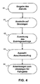
- a destination call for example via the destination call input devices ZEG or a card reader, is supplied to the multigroup control MGS.
- step 41 it checks if it is a transfer journey.
- a feeder elevator A, B, C is selected (step 42).
- an elevator from the terminal elevator group GR2 is used as a feeder elevator, since the elevators DF in this embodiment also approach the boarding platform S1. These elevators DF then drive directly to the transfer floor S4, so that a transfer journey is possible even with such a connection lift.
- a connecting elevator is assigned based on the destinations of the passengers assigned to this feeder elevator while traveling to the transfer floor (step 43).
- the connection elevator (s) assigned to the passengers in the relevant feeder elevator is / are transmitted via a display device (step 44), whereby an announcement of the connection lifts is also possible.
- Fig. 5 shows a detailed procedure of the assignment, in particular it is shown according to which criteria a feeder elevator A, B, C is assigned.
- a new destination call is input from a passenger (step 50). It is determined whether it is a travel destination that requires a change (step 51). If a change is required, in step 53 the query of several parameters.
- the number AZ1 of the intermediate stops in the floors S2-S3 between the boarding floor and the transfer floor S4 is checked and compared with a parameter AZ1MAX. Only if the number AZ1 of the intermediate stops up to the transfer floor S4, including the selected destination, is less than the parameter AZ1MAX, can this feeder elevator be assigned A or B or C for the passenger.
- the multi-group controller MGS In the feeder elevator first checked by the multi-group controller MGS, for example, A, if the number AZ1 is already larger than the parameter AZ1MAX, this feeder elevator A can not be allocated.
- the multigroup control MGS then checks the next possible feeder elevator B and then the feeder elevator C. If the first condition is met, the number of destination floors AZ2 in the upper zone Z2 of the interchange passengers booked for the feeder elevator A, B, C, including the selected destination, determined and compared with the parameter AZ2MAX.
- the feeder elevator checked by the multi-group controller MGS for example, A, can not be assigned to the passenger. In this case, the next cheapest feeder elevator is checked and assigned if it is suitable.
- step 54 the feeder elevator to be selected is transmitted to the passenger in the boarding floor S1 via a display device, for example at the destination call input device ZEG. Afterwards, the journey to the transfer floor S4 takes place (step 55). On the way to the transfer floor S4 lying in the zone Z1 Floors S2 and S3 are approached (step 56). Before the transfer floor S4 is reached (step 57), a connecting elevator DF is selected (step 58).
- the allocation of the connecting elevator D, E, F is supplemented by the following condition in addition to the cost optimization: Only if the number of destinations AZ3 of the connecting elevator, including all destinations of the passengers entering or leaving this connecting elevator, is smaller than a parameter AZ3MAX can a Elevator as connecting elevator to be determined and assigned. Otherwise, the next cheapest elevator is examined and assigned if it is suitable. In the next step 59, the passengers are still informed in the feeder elevator of the terminal elevator to be used. At step 60, the boarding or transfer to the connecting elevator on the transfer floor S4 takes place.
- the elevator is selected which can reach this destination directly (step 52) and a normal one takes place Signaling of the elevator to be used (step 61).
- the above conditions take into account the longer transfer journey and provide clear and comprehensible information about the connecting lifts D-F, which is communicated to the transfer passengers located in the feeder elevator during the feeder journey via display devices.
- the number AAZ of the assignable terminal lifts D, E, F is limited to an automatically controlled minimum, for example 1 to 2 elevators, even with different destination floors.
- the transmission of information in the form of a display or announcement in the arriving on the transfer floor S4 feeder elevator easier and easy to understand.
- This purposeful simplification of the information reduces the likelihood that one of the passengers will miss the connecting elevator. This makes it possible that passengers from a feeder lift in at most two different terminal lifts must change or transfer, so that the information transmission remains simple and thus the passenger flows in the transfer deck not too mixed.
- each transfer passenger in the feeder elevator can be given the information corresponding to each assigned connection lift, for example, destination floor S35, change to elevator D, 8 m to the left, arrival in 22 seconds.
- the information may be, for example: destination floor S56, change to elevator F, 6 m to the right. Arrival in 36 s.
- the transfer passengers of, for example, two feeder lifts may, under certain circumstances, be assigned the same connecting lift, provided that the connecting lift is the best lift for the transfer passengers from both feeder lifts.
- the corresponding investigation of the transfer problem described above is carried out continuously by the transfer control unit USE which communicates continuously with the multigroup control MGS and influences the elevator allocations to the individual destinations as required and operating modes and if necessary also adapts the limiting parameters AZ1MAX, AZ2MAX and AZ3MAX. The result is an optimal travel time for passengers and optimal process management for the operator.
Description
Die Erfindung betrifft ein Verfahren zur Steuerung einer im Zonenbetrieb betriebenen Aufzugsanlage, bei dem in einem Umsteigestockwerk ein Umsteigen zwischen Zonen ermöglicht wird und bei dem mit wenigstens einer Zubringeraufzugsgruppe und wenigstens einer Anschlussaufzugsgruppe ein Transport zum oder vom Umsteigestockwerk realisiert wird. Die wenigstens eine Zubringeraufzugsgruppe umfasst jeweils mehrere Zubringeraufzüge, die eine erste Zone unterhalb eines Umsteigestockwerkes und das Umsteigestockwerk anfahren. Die wenigstens eine Anschlussaufzugsgruppe umfasst jeweils mehrere Anschlussaufzüge, die das Umsteigestockwerk und die darüber gelegenen Stockwerke einer zweiten Zone anfahren. Die Fahrziele werden über eine Zielrufeingabe eingegeben. Die Zubringeraufzugsgruppe und die Anschlussaufzugsgruppe werden in einer Multigruppe zusammengefasst, die von einer Multigruppensteuerung gesteuert wird. Ausserdem betrifft die Erfindung eine Aufzugsanlage mit mehreren eine Zielrufsteuerung aufweisenden Aufzugsgruppen in Gebäuden.The invention relates to a method for controlling an elevator system operated in zone operation, in which a transfer between zones is made possible in a transfer floor and in which transport to or from the transfer floor is realized with at least one feeder elevator group and at least one terminal elevator group. The at least one feeder elevator group comprises in each case a plurality of feeder elevators which approach a first zone below a transfer floor and the transfer floor. The at least one connecting elevator group comprises in each case a plurality of connecting elevators which approach the transfer floor and the floors above it of a second zone. The destinations are entered via a destination call input. The feeder elevator group and the terminal elevator group are grouped in a multigroup controlled by a multigroup control. In addition, the invention relates to an elevator installation with a plurality of destination call control having elevator groups in buildings.
Für den steigenden Transportbedarf in hohen Gebäuden werden intelligente Aufzugssteuerungen eingesetzt. Dazu wird das Gebäude vertikal in zwei oder mehrere Zonen oder Stockwerkbereiche geteilt. In jeder dieser Zonen können eine oder auch mehrere Aufzugsgruppen den Transport insbesondere von Passagieren realisieren. Bei einer Vielzahl von Stockwerken ist beim vertikalen Transport oft ein Umsteigen von einem ersten Aufzug in einen anderen Aufzug notwendig. Dabei ist der zuerst benutzte Aufzug ein Zubringeraufzug aus einer Zubringeraufzugsgruppe, die die Passagiere in Stockwerke einer ersten Zone und in ein Umsteigestockwerk befördert. Das Umsteigestockwerk zwischen den Zonen wird auch als Sky-Lobby bezeichnet. An das Umsteigestockwerk schliesst sich die zweite Zone an. Dort steigen Passagiere mit Fahrzielen in der zweiten Zone in einen Anschlussaufzug aus einer Anschlussaufzugsgruppe um. Eine Fahrt, die ein Umsteigen von der Zubringeraufzugsgruppe in die Anschlussaufzugsgruppe erfordert, wird dabei als Umsteigefahrt bezeichnet. Hingegen wird eine Fahrt, bei der das Fahrziel ohne ein Umsteigen erreichbar ist, als Direktfahrt bezeichnet. Sobald jedoch für das Erreichen eines höheren Stockwerkbereiches ein Umsteigen notwendig ist, können sich bei hohem Transportaufkommen in dem Umsteigestockwerk Warteschlangen bilden. Diese werden hauptsächlich durch ungleiche Transportkapazitäten zwischen der Zubringeraufzugsgruppe und der Anschlussaufzugsgruppe verursacht, aber auch von einer ungesteuerten Zuweisung von Umsteigepassagieren in den Zubringeraufzug.Intelligent elevator controls are used to meet the increasing demand for transportation in tall buildings. For this purpose, the building is divided vertically into two or more zones or floor areas. In each of these zones, one or more elevator groups can realize the transport of passengers in particular. In the case of a large number of storeys, vertical transport often requires a change from a first elevator to another elevator. In this case, the elevator used first is a feeder elevator of a feeder elevator group that carries the passengers in floors of a first zone and in a transfer floor. The interchange between the zones is also known as the sky lobby. To the Transfer floor is followed by the second zone. There, passengers with destinations in the second zone transfer to a connecting elevator from a terminal elevator group. A trip that requires a transfer from the feeder elevator to the adjacent elevator group is referred to as a transfer service. By contrast, a journey in which the destination is reachable without a change, referred to as a direct drive. However, as soon as a change is necessary to reach a higher floor area, queues may form in the transfer floor at high transport volumes. These are mainly caused by unequal transport capacities between the feeder elevator group and the terminal elevator group, but also by an uncontrolled allocation of transfer passengers to the feeder elevator.
Aufzüge in sehr hohen Gebäuden beanspruchen einen bedeutenden Teil des Querschnitts des Gebäudes. Da das Raumangebot in den Umsteigestockwerken meistens begrenzt ist, lässt sich das Platzproblem im Umsteigestockwerk nicht ohne vergleichsweise grossen baulichen und finanziellen Aufwand realisieren.Elevators in very tall buildings occupy a significant part of the building's cross-section. Since the space in the transfer floors is usually limited, the space problem in the transfer floor can not be realized without comparatively large structural and financial costs.
Bei den konventionellen "Zweiknopf-Steuerungen" existiert meist keine verkehrsoptimierende Verbindung zwischen der Zubringeraufzugsgruppe und der Anschlussaufzugsgruppe. Es sind zwar Lösungen bekannt, um beispielsweise die Ankunftszeit des Zubringeraufzuges und des Anschlussaufzuges zu synchronisieren, diese weisen jedoch diverse Nachteile auf. So ist die Verzögerung des Zubringeraufzuges die realistischere Variante, weil die Verkürzung der Ankunftszeit des Anschlussaufzuges durch eine dynamische Änderung der Beschleunigung, Geschwindigkeit oder Kürzung der Türöffnungszeit entweder technisch nicht möglich ist (elektrische Leistung, Verkehrsdichte etc.) oder für eine Verkehrsoptimierung kontraproduktiv ist (Auslassen der Halte).In the conventional "two button controls" there is usually no traffic-optimizing connection between the feeder elevator group and the terminal elevator group. Although solutions are known to synchronize, for example, the arrival time of the feeder elevator and the connecting elevator, but these have various disadvantages. Thus, the delay of the feeder elevator is the more realistic variant, because the shortening of the arrival time of the connecting elevator by a dynamic change of acceleration, speed or reduction of the door opening time either technically impossible (electrical power, traffic density, etc.) or counterproductive for traffic optimization (omission the holding).
Ausserdem bietet die konventionelle Steuerung keine frühzeitige Erkennungsmöglichkeit der Notwendigkeit einer Umsteigefahrt, so dass keine wirkungsvollen Massnahmen für die Vereinfachung des Umsteigeprozesses möglich sind.
In der
Der Nachteil der bisherigen Lösungen mit Zielrufsteuerungen liegt aber darin, dass eine Zuweisung der Umsteigepassagiere in den zuerst benutzten Zubringeraufzug ungeachtet der Endziele der einzelnen Passagiere und der Anzahl der Endziele erfolgt. So kann es vorkommen, dass in einem Zubringeraufzug nur Passagiere transportiert werden, deren Fahrziele alle in einer zweiten Zone liegen, wobei jedoch jeder Passagier in einem anderen Stockwerk in der zweiten Zone aussteigen möchte. Diese ungesteuerte Zuweisung erfordert eine aufwendige und bisweilen auch missverständliche Signalisierung der Anschlussaufzüge. Weiter ist es mit den bisherigen Lösungen nicht möglich, die Passagiere den Zubringeraufzügen so zuzuweisen, dass die Passagiere eines bestimmten Zubringeraufzugs zusammen in den gleichen Anschlussaufzug umsteigen können, der nur eine begrenzte Anzahl von Fahrzielen anfährt. Es könnte mit den bisher bekannten Verfahren zur Steuerung vorkommen, dass Passagiere mit sich ausschliessenden Eigenschaften, beispielsweise einer umgekehrten Fahrtrichtung des Anschlussaufzugs, das heisst Verteilung der Passagiere vom Umsteigestockwerk in Aufwärts- und Abwärtsrichtung, den gleichen Zubringeraufzug zugewiesen erhielten. Auch die Anzahl der Umsteigepassagiere mit verschiedenen Fahrtzielen im Zubringeraufzug und im Anschlussaufzug ist bisher nicht auf eine vernünftige Zahl begrenzbar.Moreover, the conventional control system does not provide early recognition of the necessity of a transfer journey, so that no effective measures for simplifying the transfer process are possible.
In the
The disadvantage of the previous solutions with destination call controls, however, is that an assignment of the transfer passengers in the first feeder elevator used regardless of the final destination of the individual passengers and the number of final destinations is done. Thus, it may happen that in a feeder elevator only passengers are transported, whose destinations are all in a second zone, but each passenger wants to get off on a different floor in the second zone. This uncontrolled assignment requires a complex and sometimes misleading signaling the connection lifts. Further, with the previous solutions, it is not possible to assign the passengers to the feeder lifts so that the passengers of a particular feeder elevator can travel together to the same terminal lift, which only services a limited number of destinations. It could occur with the previously known methods for controlling that passengers with exclusive characteristics, for example, a reverse direction of travel of the terminal elevator, that is, distribution of passengers from the transfer floor in the up and down direction, the same feeder elevator assigned. Also the number of transfer passengers with different destinations in the feeder elevator and in the subsequent lift is not yet limited to a reasonable number.
Aufgabe der Erfindung ist es deshalb, eine Aufzugsanlage und ein Verfahren zur Steuerung der Aufzugsanlage anzugeben, mittels derer der Umsteigeprozess vom Zubringeraufzug zum Anschlussaufzug optimiert wird und eine kostengünstige Auslastung der Aufzugsanlage ermöglicht wird. Insbesondere ist es Aufgabe, die Rundfahrzeiten der Aufzüge zu reduzieren und die Fahrzeit der Passagiere zu reduzieren. The object of the invention is therefore to provide an elevator installation and a method for controlling the elevator installation, by means of which the transfer process from the feeder elevator to the terminal elevator is optimized and a cost-effective utilization of the elevator installation is made possible. In particular, it is an object to reduce the travel time of the lifts and to reduce the travel time of the passengers.
Diese Aufgabe wird durch die Merkmale der unabhängigen Ansprüche 1 und 13 gelöst. This object is solved by the features of
Vorteilhafte Ausgestaltungen der Erfindung sind in den Ansprüchen 2 bis 12 und 14 bis 16 angegeben.Advantageous embodiments of the invention are specified in
Die Probleme und Mängel der Aufzugssteuerungen nach dem Stand der Technik werden gemäss der vorliegenden Erfindung durch ein Verfahren zur Steuerung einer im Zonenbetrieb betriebenen Aufzugsanlage gelöst, bei dem in einem Umsteigestockwerk ein Umsteigen zwischen Zonen ermöglicht wird und bei dem mit wenigstens einer Zubringeraufzugsgruppe und wenigstens einer Anschlussaufzugsgruppe ein Transport zum oder vom Umsteigestockwerk realisiert wird. Das erfindungsgemässe Verfahren sieht zudem vor, dass die wenigstens eine Zubringeraufzugsgruppe jeweils mehrere Zubringeraufzüge umfasst, die eine erste Zone unterhalb eines Umsteigestockwerkes und das Umsteigestockwerk anfahren, und dass die wenigstens eine Anschlussaufzugsgruppe jeweils mehrere Anschlussaufzüge umfasst, die das Umsteigestockwerk und die darüber gelegenen Stockwerke einer zweiten Zone anfahren. Weiterhin werden die Fahrziele über eine Zielrufeingabe eingegeben und die Zubringeraufzugsgruppe und die Anschlussaufzugsgruppe in einer Multigruppe zusammengefasst, die von einer Multigruppensteuerung gesteuert wird. Die Multigruppensteuerung weist mittels der Zielrufeingabe einen Zubringeraufzug in Abhängigkeit von der Anzahl der Fahrziele des Zubringeraufzuges in der ersten Zone und/oder in Abhängigkeit von der Anzahl der Fahrziele der einem Zubringeraufzug zugewiesenen Passagiere in der zweiten Zone zu.The problems and shortcomings of the elevator controls of the prior art are solved according to the present invention by a method for controlling a zone-operated elevator installation, which allows a transfer between zones in a transfer floor and at least one feeder elevator group and at least one terminal elevator group a transport to or from the transfer floor is realized. The method according to the invention also provides for the at least one feeder elevator group to each comprise a plurality of feeder lifts which approach a first zone below a transfer floor and the transfer floor, and the at least one terminal elevator group respectively comprises a plurality of terminal elevators comprising the transfer floor and the floors above it a second one Approach zone. Furthermore, the travel destinations are entered via a destination call input and the feeder elevator group and the terminal elevator group are combined in a multi-group, which is controlled by a multigroup control. The multigroup control points by means of the destination call input a feeder elevator depending on the number of destinations of the feeder elevator in the first zone and / or in dependence on the number of destinations of the passengers assigned to a feeder elevator in the second zone.
Der Erfindung liegt der Gedanke zugrunde, die durch die Zielrufeingabe gewonnene Information so früh wie möglich zur Optimierung der Fahrzeit einzusetzen. Dabei wird durch die erfindungsgemässe Ausgestaltung ein effizientes Umsteigemanagement ermöglicht mit dem Ergebnis, dass die Rundfahrtszeiten der Aufzüge verkürzt werden und damit die gesamte Fahrzeit der Umsteigepassagiere optimiert wird. Ausserdem wird eine übersichtliche Signalisierung und Anweisung für die Umsteigepassagiere ermöglicht.The invention is based on the idea to use the information obtained by the destination call input as early as possible to optimize the driving time. In this case, an efficient transfer management is made possible by the inventive design with the result that the round trip times of the lifts are shortened and thus the entire journey time of the transfer passengers is optimized. In addition, a clear signaling and instruction for the transfer passengers is made possible.
In einer bevorzugten Ausführungsform wird bei der Zuweisung eines Zubringeraufzuges die Anzahl der Passagiere mit unterschiedlichen Fahrzielen in der ersten Zone begrenzt, wobei die Anzahl der Zwischenhalte zwischen einem Einsteigestockwerk und dem Umsteigestockwerk erfasst und mit einem Parameter für die maximale Anzahl von Zwischenhalten des Zubringeraufzuges verglichen wird und ein Zubringeraufzug nur dann zugewiesen wird, wenn die Anzahl der Zwischenhalte des Zubringeraufzuges kleiner als der Parameter für die maximale Anzahl von Zwischenhalten ist. Dadurch wird es ermöglicht, dass ein Zubringeraufzug einerseits nicht in vielen Stockwerken der ersten Zone anhalten muss. Andererseits wird in dem jeweiligen Zubringeraufzug ausserdem noch Transportkapazität für die Fahrt in die Stockwerke der zweiten Zone freigelassen, die geringer ausfallen würde, wenn dem Zubringeraufzug viele Passagiere mit allen möglichen Fahrzielen der ersten Zone zugewiesen würden.In a preferred embodiment, in allocating a feeder elevator, the number of passengers having different destinations in the first zone is limited, the number of intermediate stops between a boarding floor and the interchange floor being detected and compared with a parameter for the maximum number of interrupts of the feeder elevator, and a feeder elevator is assigned only if the number of intermediate stops of the feeder elevator is less than the parameter for the maximum number of intermediate stops. This makes it possible for a feeder elevator to not have to stop on many floors of the first zone on the one hand. On the other hand, in the respective feeder elevator transport capacity is still left for the drive to the floors of the second zone, which would be less if the feeder elevator many passengers were assigned with all possible destinations of the first zone.
In einer weiteren Ausgestaltung der Erfindung wird bei der Zuweisung eines Zubringeraufzuges die Anzahl der Passagiere mit unterschiedlichen Fahrzielen in der zweiten Zone begrenzt, wobei die Anzahl von unterschiedlichen Zielstockwerken der dem Zubringeraufzug zugewiesenen Passagiere in der zweiten Zone erfasst und mit einem Parameter für unterschiedliche Fahrziele in der zweiten Zone verglichen wird und wobei ein Zubringeraufzug nur dann zugewiesen wird, wenn die Anzahl von unterschiedlichen Zielstockwerken in der zweiten Zone des Zubringeraufzuges kleiner als der Parameter für die unterschiedlichen Fahrziele in der zweiten Zone ist. Dadurch wird es ermöglicht, dass in einem Zubringeraufzug nur eine begrenzte Anzahl von Umsteigepassagieren mit unterschiedlichen Fahrzielen befördert wird. So lässt sich beispielsweise die Anzahl der Passagiere mit unterschiedlichen Zielstockwerken in der zweiten Zone auf zwei begrenzen, so dass aus diesem Zubringeraufzug im Umsteigestockwerk nur zwei Gruppen von Umsteigepassagieren aussteigen und die Signalisierung der Anschlussaufzüge entsprechend einfach bleibt und ein Vermischen aller Umsteigepassagiere auf dem Umsteigestockwerk strategisch unterbunden wird.In a further embodiment of the invention, in the allocation of a feeder elevator, the number of passengers with different destinations in the second zone is limited, the number of different destination floors of the passengers assigned to the feeder elevator in the second zone second zone is detected and compared with a parameter for different destinations in the second zone and wherein a feeder elevator is assigned only if the number of different destination floors in the second zone of the feeder elevator is smaller than the parameter for the different destinations in the second zone , This allows a feeder elevator to carry only a limited number of transfer passengers with different destinations. For example, the number of passengers with different destination floors in the second zone can be limited to two, so that only two groups of transfer passengers get out of this feeder elevator in the transfer floor and the signaling of the connecting lifts remains correspondingly simple and strategically inhibits mixing of all transfer passengers on the transfer floor becomes.
In einer weiteren Ausgestaltung der Erfindung wird die Anzahl an zuweisbaren Anschlussaufzügen im Umsteigestockwerk auf einen Parameter für die maximal zuweisbaren Anschlussaufzüge begrenzt. Dadurch wird das Vermischen der Umsteigepassagiere auf dem Umsteigestockwerk weitestgehend unterbunden.In a further embodiment of the invention, the number of assignable connection lifts in the transfer floor is limited to a parameter for the maximum assignable connection lifts. As a result, the mixing of the transfer passengers on the transfer floor is largely prevented.
In einer weiteren Ausgestaltung der Erfindung wird bei der Zuweisung des Anschlussaufzuges die Anzahl an Zielen des jeweils zugewiesenen Anschlussaufzuges begrenzt, wobei die Anzahl von Zielen im Anschlussaufzug erfasst und mit einem Parameter für die maximale Anzahl an Zielen des Anschlussaufzugs verglichen wird, wobei ein Anschlussaufzug nur dann zugewiesen wird, wenn die Anzahl von Zielen im Anschlussaufzug kleiner als der vorherbestimmte Parameter für die maximale Anzahl Ziele des Anschlussaufzugs ist. Dies hat den Vorteil, dass die Weiterfahrt mit den Anschlussaufzügen nicht durch sehr viele Zwischenhalte in der zweiten Zone Z2 verlängert wird und somit eine optimale Fahrzeit erreicht wird.In a further embodiment of the invention, in the assignment of the terminal elevator, the number of destinations of the respectively assigned terminal elevator is limited, the number of destinations in the terminal elevator being detected and compared with a parameter for the maximum number of destinations of the terminal elevator, a terminal elevator only then is assigned when the number of destinations in the subsequent elevator is less than the predetermined parameter for the maximum number of destinations of the terminal elevator. This has the advantage that the onward journey with the connection lifts is not prolonged by a large number of intermediate stops in the second zone Z2, and thus an optimum travel time is achieved.
In einer weiteren Ausgestaltung der Erfindung kann bei der Zuweisung des Zubringeraufzugs die Anzahl der Umsteigepassagiere begrenzt werden .In a further embodiment of the invention, the number of transfer passengers can be limited in the allocation of the feeder elevator.
In einer weiteren Ausgestaltung der Erfindung kann bei der Zuweisung des Anschlussaufzugs die Anzahl der Umsteigepassagiere begrenzt werden .In a further embodiment of the invention, the number of transfer passengers can be limited in the allocation of the connecting elevator.
In einer weiteren Ausgestaltung der Erfindung wird mittels einer Sonderstatustaste die Multigruppensteuerung beeinflusst, so dass bei der Zuweisung der Zubringeraufzüge und der Anschlussaufzüge für Passagiere mit Sonderstatus eine längere oder kürze Umsteigezeit berücksichtigt werden kann.In a further embodiment of the invention, the multigroup control is influenced by means of a special status key, so that a longer or shorter transfer time can be taken into account when assigning the feeder lifts and connecting elevators for passengers with special status.
Ausserdem ist vorteilhafterweise vorgesehen, die Signalisierung des zu wählenden Anschlussaufzugs im Zubringeraufzug anzuzeigen. Dadurch wissen die Umsteigepassagiere schon vor dem Aussteigen im Umsteigestockwerk, mit welchem Anschlussaufzug sie weiterfahren und in welche Richtung sie gehen müssen und wann oder in wieviel Sekunden oder Minuten der Anschlussaufzug abfährt.In addition, it is advantageously provided to indicate the signaling of the terminal elevator to be selected in the feeder elevator. Thus, the transfer passengers already know before getting off in the transfer floor, with which connecting lift they continue and in which direction they have to go and when or in how many seconds or minutes, the connecting elevator leaves.
Die Aufgabe wird ferner von einer Aufzugsanlage mit mehreren Aufzugsgruppen mit Zielrufsteuerung in Gebäuden gelöst, die wenigstens eine Zubringeraufzugsgruppe mit mehreren Zubringeraufzügen und wenigstens eine Anschlussaufzugsgruppe mit mehreren Anschlussaufzügen umfasst. Die Zubringeraufzüge der Zubringeraufzugsgruppe fahren eine erste Zone des Gebäudes an, und die Anschlussaufzüge der Anschlussaufzugsgruppe fahren eine zweite Zone des Gebäudes an. Die Aufzugsgruppen fahren zudem gemeinsam wenigstens ein Umsteigestockwerk an. Die Aufzugsanlage weist überdies Anzeigevorrichtungen zur Anzeige des zu wählenden Aufzugs und eine Multigruppensteuerung zur Steuerung der Zubringeraufzugsgruppe und der Anschlussaufzugsgruppe auf. Nach einer ersten Zielrufeingabe ist der günstigste Zubringeraufzug aus der Zubringeraufzugsgruppe in Abhängigkeit von einem Parameter für eine Höchstgrenze von Fahrzielen des Zubringeraufzuges in der ersten Zone und/oder von einem Parameter für eine Höchstgrenze von Fahrzielen in der zweiten Zone auswählbar.The object is further achieved by an elevator system with several elevator groups with destination call control in buildings, comprising at least one feeder elevator group with a plurality of feeder lifts and at least one connecting elevator group with a plurality of terminal elevators. The feeder elevators of the feeder elevator group start a first zone of the building, and the terminal elevators of the terminal elevator group drive a second zone of the building. The elevator groups also drive together at least one transfer deck. The elevator installation furthermore has display devices for displaying the elevator to be selected and a multigroup control for controlling the feeder elevator group and the connection elevator group. After a first destination call input, the least expensive feeder elevator from the feeder elevator group is a function of a parameter for a maximum limit of destinations of the feeder elevator in the first zone and / or from a parameter for a maximum of destinations in the second zone selectable.
Es wird davon ausgegangen, dass der kundige Leser erkennt, dass Zubringer- und Anschlussaufzugsgruppe je nach Fahrtrichtung vertauscht werden können. Ebenso kann je nach Fahrtrichtung die Reihenfolge der benutzen Zonen vertauscht sein. So ist beispielsweise bei Fahrtrichtung von oben nach unten die zweite Zone die zuerst benutzte Zone. Um eine bessere Übersichtlichkeit und Verständlichkeit zu gewährleisten, wird die Erfindung im Folgenden nur anhand der Fahrtrichtung von unten nach oben im Gebäude beschrieben, so dass die erste Zone die untere Zone und die zweite Zone die obere Zone ist. Des Weiteren kann die Erfindung leicht auf mehrere Aufzugsgruppen übertragen werden, wobei sich dann jedoch die Anzahl der zu überwachenden Parameter bezüglich der maximalen Anzahl der Fahrziele in den einzelnen Zonen erhöht.It is assumed that the knowledgeable reader recognizes that the feeder and connection elevator groups can be reversed depending on the direction of travel. Likewise, depending on the direction of travel, the order of the zones used can be reversed. For example, in the direction of travel from top to bottom, the second zone is the first zone used. In order to ensure better clarity and comprehensibility, the invention is described below only with reference to the direction of travel from bottom to top in the building, so that the first zone is the lower zone and the second zone is the upper zone. Furthermore, the invention can be easily transferred to several elevator groups, but then increases the number of parameters to be monitored with respect to the maximum number of destinations in the individual zones.
Im folgenden wird die Erfindung anhand von lediglich ein Ausführungsbeispiel darstellenden schematischen Zeichnungen näher erläutert: Es zeigen:
- Fig. 1
- den Aufbau einer Multigruppensteuerung bei einer Aufzugsanlage gemäss der vorliegenden Erfindung;
- Fig. 2
- eine Aufteilung eines Gebäudes in mehrere Zonen;
- Fig. 3
- einen detaillierten Aufbau einer Aufzugsanlage gemäss der vorliegenden Erfindung;
- Fig. 4
- ein Ablaufdiagramm der Zuweisung eines Zubringeraufzuges und Zuweisung eines Anschlussaufzuges gemäss der vorliegenden Erfindung und
- Fig. 5
- ein detailliertes Ablaufdiagramm der Zuweisung eines Zubringeraufzuges und Zuweisung eines Anschlussaufzugs gemäß der vorliegenden Erfindung.
- Fig. 1
- the construction of a multi-group control in an elevator system according to the present invention;
- Fig. 2
- a division of a building into several zones;
- Fig. 3
- a detailed structure of an elevator system according to the present invention;
- Fig. 4
- a flowchart of the assignment of a feeder elevator and assignment of a terminal elevator according to the present invention and
- Fig. 5
- a detailed flow chart of the allocation of a feeder elevator and assignment of a terminal elevator according to the present invention.
In
In
In
In
Die obgenannten Bedingungen tragen der längeren Umsteigefahrt Rechnung und ermöglichen eine übersichtliche und auffassbare Information über die Anschlussaufzüge D-F, die den im Zubringeraufzug befindlichen Umsteigepassagieren noch während der Zubringerfahrt über Anzeigevorrichtungen mitgeteilt wird.The above conditions take into account the longer transfer journey and provide clear and comprehensible information about the connecting lifts D-F, which is communicated to the transfer passengers located in the feeder elevator during the feeder journey via display devices.
Für die Passagiere in einem Zubringeraufzug A, B, C wird die Anzahl AAZ der zuweisbaren Anschlussaufzüge D, E, F auch bei unterschiedlichen Zielstockwerken auf ein automatisch gesteuertes Minimum, beispielsweise 1 bis 2 Aufzüge, begrenzt. Damit wird die Informationsübermittlung in Form einer Anzeige oder Ansage im auf dem Umsteigestockwerk S4 ankommenden Zubringeraufzug einfacher und leicht verständlich. Durch diese zielbewusste Vereinfachung der Information wird die Wahrscheinlichkeit verringert, dass einer der Passagiere den Anschlussaufzug verpasst. Somit wird es ermöglicht, dass Passagiere aus einem Zubringeraufzug in höchstens zwei unterschiedliche Anschlussaufzüge ein- oder umsteigen müssen, so dass die Informationsübermittlung einfach bleibt und sich somit die Passagierströme im Umsteigestockwerk auch nicht zu stark vermischen.For the passengers in a feeder elevator A, B, C, the number AAZ of the assignable terminal lifts D, E, F is limited to an automatically controlled minimum, for example 1 to 2 elevators, even with different destination floors. Thus, the transmission of information in the form of a display or announcement in the arriving on the transfer floor S4 feeder elevator easier and easy to understand. This purposeful simplification of the information reduces the likelihood that one of the passengers will miss the connecting elevator. This makes it possible that passengers from a feeder lift in at most two different terminal lifts must change or transfer, so that the information transmission remains simple and thus the passenger flows in the transfer deck not too mixed.
Grundlage für diese vereinfachte Information über den Anschlussaufzug ist die anfangs genannte Begrenzung der Halte, die einem Zubringeraufzug A, B, C zugewiesen werden können. Ausserdem wird von der Multigruppensteuerung MGS die Zeit, die zum Umsteigen zur Verfügung steht, berechnet. Diese Zeit ergibt sich beispielsweise aus der Anzahl aller Umsteigepassagiere, wobei jedem Umsteigepassagier eine Zeiteinheit von beispielsweise 1 Sekunde zugeteilt wird. Bei älteren oder gehbehinderten Passagieren kann diese Zeiteinheit länger gewählt werden. Ausserdem wird noch die Zeit für den Anmarschweg vom Zubringeraufzug zum Anschlussaufzug und eine wählbare Reservezeit hinzu addiert. Weiter kann eine eventuelle Wartezeit auf den Anschlussaufzug hinzugefügt werden. Somit kann jedem Umsteigepassagier im Zubringeraufzug die für jeden zugewiesenen Anschlussaufzug entsprechende Information gegeben werden, beispielsweise Fahrziel Stockwerk S35, Umsteigen in Aufzug D, 8 m nach links, Ankunft in 22 s. Für die andere(n) Gruppe/Gruppen von Umsteigepassagieren im Zubringeraufzug kann die Information beispielsweise lauten: Fahrziel Stockwerk S56, Umsteigen in Aufzug F, 6 m nach rechts. Ankunft in 36 s.The basis for this simplified information about the connecting elevator is the initially mentioned limitation of the stops that can be assigned to a feeder elevator A, B, C. In addition, the multi-group control MGS calculates the time available for transfer. This time results, for example, from the number of all transfer passengers, with each transfer passenger having a time unit of, for example, 1 second. For elderly or handicapped passengers, this time unit can be selected longer. In addition, the time for the approach route from the feeder elevator to the connecting elevator and a selectable reserve time is added. Furthermore, a possible waiting time can be added to the connecting elevator. Thus, each transfer passenger in the feeder elevator can be given the information corresponding to each assigned connection lift, for example, destination floor S35, change to elevator D, 8 m to the left, arrival in 22 seconds. For the other group (s) of transfer passengers in the feeder elevator, the information may be, for example: destination floor S56, change to elevator F, 6 m to the right. Arrival in 36 s.
Alle Passagiere aus dem Zubringeraufzug steigen in eine begrenzte Anzahl von verschiedenen Anschlussaufzügen um. Der Anhaltevorgang des Zubringeraufzuges und der Anmarschweg zum jeweiligen Anschlussaufzug sind bei der Auswahl des Anschlussaufzuges einberechnet, womit der Umsteigeprozess optimiert wird.All passengers from the feeder lift move to a limited number of different connecting lifts. The stopping process of the feeder elevator and the approach path to the respective connecting elevator are included in the selection of the connecting elevator, whereby the transfer process is optimized.
Auch eine Gruppierung von langsamen Passagieren mit schnelleren Passagieren rief bei Lösungen aus dem Stand der Technik Probleme beim Umsteigen hervor. Denn es musste beispielsweise im Umsteigestockwerk ein Sonderstatus, beispielsweise ein "handicapped call", eingegeben werden. Durch die neu vorgeschlagene Lösung sind alle wichtigen Attribute jedes Passagiers schon seit der ersten und einzig notwendigen Zielrufeingabe im Einsteigestockwerk S1 automatisch mitberücksichtigt. Für die langsameren Passagiere, welche sich via spezieller "handicapped Taste" oder zum Beispiel via Kartenleser mit einem Sonderstatus bei der Multigruppensteuerung MGS identifizieren, wird eine längere, zum Umsteigen notwendige Zeit eingerechnet.Also, grouping of slower passengers with faster passengers caused problems with transfers in prior art solutions. Because, for example, there had to be a special status in the transfer floor, For example, a "handicapped call", be entered. Due to the newly proposed solution, all the important attributes of each passenger have been automatically taken into account since the first and only necessary destination call input in the boarding floor S1. For the slower passengers, who identify themselves via a special "handicapped button" or, for example, via card readers with a special status in the multigroup control MGS, a longer time necessary for transfer is included.
Die Umsteigepassagiere von zum Beispiel zwei Zubringeraufzügen können unter Umständen denselben Anschlussaufzug zugewiesen bekommen, sofern der Anschlussaufzug jeweils für die Umsteigepassagiere aus beiden Zubringeraufzügen der beste Aufzug ist. Die entsprechende Untersuchung der oben beschriebenen Umsteigeproblematik wird kontinuierlich durch die Umsteigesteuerungseinheit USE durchgeführt, die mit der Multigruppensteuerung MGS ständig kommuniziert und je nach Bedarf und Betriebsmodi die Aufzugszuweisungen zu den einzelnen Fahrzielen beeinflusst und gegebenenfalls auch die begrenzenden Parameter AZ1MAX, AZ2MAX und AZ3MAX anpasst. Das Resultat ist eine für die Passagiere optimale Fahrtzeit und für den Betreiber eine optimale Prozessführung.The transfer passengers of, for example, two feeder lifts may, under certain circumstances, be assigned the same connecting lift, provided that the connecting lift is the best lift for the transfer passengers from both feeder lifts. The corresponding investigation of the transfer problem described above is carried out continuously by the transfer control unit USE which communicates continuously with the multigroup control MGS and influences the elevator allocations to the individual destinations as required and operating modes and if necessary also adapts the limiting parameters AZ1MAX, AZ2MAX and AZ3MAX. The result is an optimal travel time for passengers and optimal process management for the operator.
Es ist zu beachten, dass alle (Umsteige-) Fahrten nicht nur von "unten" nach "oben", sondern auch in umgekehrter Richtung möglich sind.It should be noted that all (transfer) journeys are possible not only from "below" to "above", but also in the opposite direction.
Claims (16)
- Method of controlling an elevator installation with zone assignation and destination control system in whicha) on an interchange floor (S4) changing between zones (Z1, Z2) is made possible;b) with at least one feeder-elevator group (GR1) and at least one connecting-elevator group (GR2) transportation to or from the interchange floor (S4) is realized, the at-least one feeder-elevator group (GR1) comprising in each case several feeder elevators (A, B, C) which travel to a first zone (Z1) below an interchange floor (S4) and to the interchange floor (S4), and the at-least one connecting-elevator group (GR2) comprising in each case several connecting elevators (D, E, F) which travel to the interchange floor (S4) and the floors (S5-Sn) of a second zone (Z2) located above it;c) the trip destinations are entered to the destination control system via a destination-call input;
andd) the feeder-elevator group (GR1) and the connecting-elevator group (GR2) are controlled by a multigroup control (MGS);characterized in that, by means of the destination-call input, the multigroup control (MGS) allocates a feeder elevator (A, B, C) depending on the number of trip destinations of the feeder elevator (A, B, C) in the first zone (Z1) and depending on the number of trip destinations in the second zone (Z2) of the passengers allocated to a feeder elevator (A, B, C). - Method according to Claim 1, characterized in that, on allocation of a feeder elevator (A, B, C), the number of passengers with different trip destinations in the first zone (Z1) is limited.
- Method according to Claim 1 or 2, characterized in that, on allocation of a feeder elevator (A, B, C), the number of changing passengers in the feeder elevator (A, B, C) is limited.
- Method according to one of claims 1 to 3, characterized in that, on allocation of a feeder elevator (A, B, C), the number (AZ1) of intermediate stops between a boarding floor (S1-Sn) and the interchange floor (S4) is registered and compared with a parameter (AZ1MAX) for the maximum number of intermediate stops of the feeder elevator (A, B, C), and a feeder elevator (A, B, C) is only allocated if the number (AZ1) of intermediate stops of the feeder elevator (A, B, C) is less than the parameter (AZ1MAX).
- Method according to Claim 4, characterized in that, on reaching the maximum number of intermediate stops (AZ1MAX) between the boarding floor (S1-Sn) and the interchange floor (S4), a feeder elevator (A, B, C) is only allocated if the destination-call input entered relates to a floor which is already booked (S1-S3) and the maximum transportation capacity is not exceeded.
- Method according to one of claims 1 to 5, characterized in that, on allocation of a feeder elevator (A, B, C), the number of passengers with different trip destinations in the second zone (Z2) is limited, the number (AZ2) of target floors in the second zone (Z2) of the passengers allocated to the feeder elevator (A, B, C) is registered and compared with a parameter (AZ2MAX) for different trip destinations in the second zone (Z2), and a feeder elevator (A, B, C) is only allocated if the number (AZ2) of different target floors in the second zone (AZ2) of the feeder elevator (A, B, C) is less than the parameter (AZ2MAX).
- Method according to one of claims 1 to 6, characterized in that the number (AAZ) of allocatable connecting elevators (D, E, F) on the interchange floor (S4) is limited by a parameter (AAZMAX) for the maximum allocatable connecting elevators (D, E, F).
- Method according to one of claims 1 to 7, characterized in that, on allocation of the connecting elevator (D, E, F), the number (AZ3) of destinations of the respective allocated connecting elevator (D, E, F) is limited, the number (AZ3) of destinations of the connecting elevators (D, E, F) being registered and compared with a parameter (AZ3MAX) for the maximum number of destinations of the connecting elevator (D, E, F), and a connecting elevator (D, E, F) only being allocated if the number (AZ3) of destinations of the connecting elevator (D, E, F) is less than the parameter (AZ3MAX).
- Method according to one of claims 1 to 8, characterized in that, by means of a special-status button, the multigroup control (MGS) can be influenced and, on allocating the feeder elevators (A, B, C) and the connecting elevators (D, E, F) for passengers with special status, a longer or shorter interchange time is taken into account.
- Method according to one of claims 1 to 9 characterized by signaling in the feeder elevator (A, B, C) of the connecting elevator (D, E, F) that is to be selected.
- Method according to one of claims 1 to 10, characterized in that the feeder elevator (A, B, C) and the connecting elevator (D, E, F) are allocated depending on cost rules.
- Method according to one of claims 1 to 11, characterized in that the parameters (AZ1MAX, AZ2MAX, AZ3MAX, AAZMAX) can be adapted by the multigroup control (MGS) depending on predeterminable operating modi.
- Elevator installation with several elevator groups (GR1, GR2) with a destination-call control comprising:a) at least one feeder-elevator group (GR1) with several feeder elevators (A, B, C) and at least one connecting-elevator group (GR2) with several connecting elevators (D, E, F), the feeder elevators (A, B, C) of the feeder-elevator group (GR1) traveling to a first zone (Z1) of a building, the connecting elevators (D, E, F) of the connecting-elevator group (GR2) traveling to a second zone (Z2) of the building, and the elevator groups (GR1, GR2) both traveling to at least one common interchange floor (S4);b) display devices for indicating the elevator to be selected (A, B, C, D, E, F); andc) a multigroup control (MGS) to control the feeder-elevator group (GR1) and the connecting-elevator group (GR2);characterized in that, after a first destination-call input to the destination control system, the lowest-cost feeder elevator (A, B, C) can be selected from the feeder-elevator group (GR1) depending on a parameter (AZ1MAX) for a maximum number of trip destinations of the feeder elevator (A, B, C) in the first zone (Z1) and depending on a parameter (AZ2MAX) for a maximum number of trip destinations in the second zone (Z2).
- Elevator installation according to Claim 13, characterized in that the connecting elevator (D, E, F) is selectable depending on a parameter (AZ3MAX) which determines a maximum number of trip destinations of the connecting elevator (D, E, F) in the second zone (Z2).
- Elevator installation according to claim 13 or 14, characterized in that the connecting-elevator group (GR2) also travels to destinations (S1) below the interchange floor (S4).
- Elevator installation according to one of claims 13 to 15, characterized in that, on allocating the connecting elevator (D, E, F), the number (AAZ) of allocatable connecting elevators (D, E, F) on the interchange floor (S4) can be limited to a parameter (AAZMAX) for the maximum allocatable connecting elevators (D, E, F).
Priority Applications (1)
| Application Number | Priority Date | Filing Date | Title |
|---|---|---|---|
| EP20040013586 EP1491481B1 (en) | 2003-06-27 | 2004-06-09 | Method for controlling an elevator group with zone assignation |
Applications Claiming Priority (3)
| Application Number | Priority Date | Filing Date | Title |
|---|---|---|---|
| EP03405473 | 2003-06-27 | ||
| EP03405473 | 2003-06-27 | ||
| EP20040013586 EP1491481B1 (en) | 2003-06-27 | 2004-06-09 | Method for controlling an elevator group with zone assignation |
Publications (2)
| Publication Number | Publication Date |
|---|---|
| EP1491481A1 EP1491481A1 (en) | 2004-12-29 |
| EP1491481B1 true EP1491481B1 (en) | 2010-02-17 |
Family
ID=33420613
Family Applications (1)
| Application Number | Title | Priority Date | Filing Date |
|---|---|---|---|
| EP20040013586 Expired - Fee Related EP1491481B1 (en) | 2003-06-27 | 2004-06-09 | Method for controlling an elevator group with zone assignation |
Country Status (1)
| Country | Link |
|---|---|
| EP (1) | EP1491481B1 (en) |
Families Citing this family (4)
| Publication number | Priority date | Publication date | Assignee | Title |
|---|---|---|---|---|
| FI121009B (en) | 2008-10-24 | 2010-06-15 | Kone Corp | Lift system |
| CN102556783A (en) * | 2011-07-12 | 2012-07-11 | 江苏镇安电力设备有限公司 | Subarea-based elevator traffic prediction group control method and elevator monitoring implementation |
| DE102014223153A1 (en) | 2014-11-13 | 2016-05-19 | Thyssenkrupp Ag | A method for processing call inputs by an elevator control and elevator installations for carrying out the methods |
| CN113247719B (en) * | 2021-05-10 | 2024-01-26 | 杭州海康威视数字技术股份有限公司 | Elevator group management and control system and method and elevator service gateway equipment |
Family Cites Families (3)
| Publication number | Priority date | Publication date | Assignee | Title |
|---|---|---|---|---|
| FI85970C (en) * | 1986-09-24 | 1992-06-25 | Kone Oy | FOERFARANDE FOER KOORDINERING AV HISSGRUPPER. |
| CA2251143C (en) * | 1996-04-03 | 2006-07-11 | Inventio Ag | Control system for a plurality of groups of lifts with destination call control system |
| US6655501B2 (en) * | 2001-06-29 | 2003-12-02 | Inventio Ag | Method for selection of the most favorable elevator of an elevator installation comprising at least two elevator groups |
-
2004
- 2004-06-09 EP EP20040013586 patent/EP1491481B1/en not_active Expired - Fee Related
Also Published As
| Publication number | Publication date |
|---|---|
| EP1491481A1 (en) | 2004-12-29 |
Similar Documents
| Publication | Publication Date | Title |
|---|---|---|
| EP0246395B1 (en) | Lift group control | |
| EP0301178B1 (en) | Lift control device | |
| EP1565396B1 (en) | Method for controlling an elevator system and elevator system for carrying out said method | |
| EP1276691B1 (en) | Targeted call control for lifts | |
| EP1418147B1 (en) | Controller for elevator with multi-deck car | |
| EP0312730B1 (en) | Group control for lifts with load dependant control of the cabins | |
| EP0440967B1 (en) | Group control for elevators with direct allocation of calls from a call input register located on the floor | |
| EP3206982B1 (en) | Method for operating a transport system and corresponding transport system | |
| EP0891291B1 (en) | Control system for a plurality of groups of lifts with destination call control system | |
| EP1619157B2 (en) | Elevator system with independently movable elevator cars and method for controlling its movement | |
| EP0199015B1 (en) | Load-dependent control device for a lift | |
| EP0091554B1 (en) | Lift groups control comprising a device for the down peak traffic control | |
| EP0459169B1 (en) | Group control for elevators with double cabins with direct allocation of calls | |
| EP0356731A1 (en) | Grouped control affording instantaneous attribution of destination calls | |
| WO2016135090A1 (en) | Method for operating a lift system having a number of shafts and a number of cars | |
| EP0624540B1 (en) | Elevator system for zone operation | |
| US7117980B2 (en) | Method and apparatus for controlling an elevator installation with zoning and an interchange floor | |
| DE3732204A1 (en) | METHOD FOR COORDINATING THE TRAFFIC OF GROUPS IN BUILDINGS WITH TRANSFER DAYS | |
| EP0134892B1 (en) | Lift group control for double-compartment cars | |
| EP0378834B1 (en) | Group control for lifts affording instantaneous attribution of destination calls | |
| EP0242520B1 (en) | Displaying device for lifts | |
| EP0308590B1 (en) | Group control for lifts affording instantaneous attribution of destination calls | |
| EP1491481B1 (en) | Method for controlling an elevator group with zone assignation | |
| EP1270486B1 (en) | Methode for selecting the most efficient way, including change of cabs, by a plurality of elevators groups | |
| DE2538871A1 (en) | INTERFACE ARRANGEMENT FOR THE TRAFFIC OF AN ELEVATOR IN AN ELEVATOR SYSTEM WITH A CENTRAL CONTROL UNIT |
Legal Events
| Date | Code | Title | Description |
|---|---|---|---|
| PUAI | Public reference made under article 153(3) epc to a published international application that has entered the european phase |
Free format text: ORIGINAL CODE: 0009012 |
|
| AK | Designated contracting states |
Kind code of ref document: A1 Designated state(s): AT BE BG CH CY CZ DE DK EE ES FI FR GB GR HU IE IT LI LU MC NL PL PT RO SE SI SK TR |
|
| AX | Request for extension of the european patent |
Extension state: AL HR LT LV MK |
|
| 17P | Request for examination filed |
Effective date: 20050617 |
|
| AKX | Designation fees paid |
Designated state(s): DE FR GB |
|
| 17Q | First examination report despatched |
Effective date: 20060929 |
|
| GRAP | Despatch of communication of intention to grant a patent |
Free format text: ORIGINAL CODE: EPIDOSNIGR1 |
|
| GRAS | Grant fee paid |
Free format text: ORIGINAL CODE: EPIDOSNIGR3 |
|
| GRAA | (expected) grant |
Free format text: ORIGINAL CODE: 0009210 |
|
| AK | Designated contracting states |
Kind code of ref document: B1 Designated state(s): DE FR GB |
|
| REG | Reference to a national code |
Ref country code: GB Ref legal event code: FG4D Free format text: NOT ENGLISH |
|
| REF | Corresponds to: |
Ref document number: 502004010757 Country of ref document: DE Date of ref document: 20100401 Kind code of ref document: P |
|
| PLBE | No opposition filed within time limit |
Free format text: ORIGINAL CODE: 0009261 |
|
| STAA | Information on the status of an ep patent application or granted ep patent |
Free format text: STATUS: NO OPPOSITION FILED WITHIN TIME LIMIT |
|
| 26N | No opposition filed |
Effective date: 20101118 |
|
| REG | Reference to a national code |
Ref country code: FR Ref legal event code: PLFP Year of fee payment: 13 |
|
| REG | Reference to a national code |
Ref country code: FR Ref legal event code: PLFP Year of fee payment: 14 |
|
| REG | Reference to a national code |
Ref country code: FR Ref legal event code: PLFP Year of fee payment: 15 |
|
| PGFP | Annual fee paid to national office [announced via postgrant information from national office to epo] |
Ref country code: DE Payment date: 20190619 Year of fee payment: 16 |
|
| PGFP | Annual fee paid to national office [announced via postgrant information from national office to epo] |
Ref country code: FR Payment date: 20190619 Year of fee payment: 16 |
|
| PGFP | Annual fee paid to national office [announced via postgrant information from national office to epo] |
Ref country code: GB Payment date: 20190619 Year of fee payment: 16 |
|
| REG | Reference to a national code |
Ref country code: DE Ref legal event code: R119 Ref document number: 502004010757 Country of ref document: DE |
|
| GBPC | Gb: european patent ceased through non-payment of renewal fee |
Effective date: 20200609 |
|
| PG25 | Lapsed in a contracting state [announced via postgrant information from national office to epo] |
Ref country code: FR Free format text: LAPSE BECAUSE OF NON-PAYMENT OF DUE FEES Effective date: 20200630 Ref country code: GB Free format text: LAPSE BECAUSE OF NON-PAYMENT OF DUE FEES Effective date: 20200609 |
|
| PG25 | Lapsed in a contracting state [announced via postgrant information from national office to epo] |
Ref country code: DE Free format text: LAPSE BECAUSE OF NON-PAYMENT OF DUE FEES Effective date: 20210101 |