EP1491481B1 - Méthode de contrôle d'un groupe d'ascenseur avec attribution de zone - Google Patents
Méthode de contrôle d'un groupe d'ascenseur avec attribution de zone Download PDFInfo
- Publication number
- EP1491481B1 EP1491481B1 EP20040013586 EP04013586A EP1491481B1 EP 1491481 B1 EP1491481 B1 EP 1491481B1 EP 20040013586 EP20040013586 EP 20040013586 EP 04013586 A EP04013586 A EP 04013586A EP 1491481 B1 EP1491481 B1 EP 1491481B1
- Authority
- EP
- European Patent Office
- Prior art keywords
- elevator
- feeder
- zone
- elevators
- floor
- Prior art date
- Legal status (The legal status is an assumption and is not a legal conclusion. Google has not performed a legal analysis and makes no representation as to the accuracy of the status listed.)
- Expired - Fee Related
Links
Images


Classifications
-
- B—PERFORMING OPERATIONS; TRANSPORTING
- B66—HOISTING; LIFTING; HAULING
- B66B—ELEVATORS; ESCALATORS OR MOVING WALKWAYS
- B66B1/00—Control systems of elevators in general
- B66B1/02—Control systems without regulation, i.e. without retroactive action
- B66B1/06—Control systems without regulation, i.e. without retroactive action electric
- B66B1/14—Control systems without regulation, i.e. without retroactive action electric with devices, e.g. push-buttons, for indirect control of movements
- B66B1/18—Control systems without regulation, i.e. without retroactive action electric with devices, e.g. push-buttons, for indirect control of movements with means for storing pulses controlling the movements of several cars or cages
Definitions
- the invention relates to a method for controlling an elevator system operated in zone operation, in which a transfer between zones is made possible in a transfer floor and in which transport to or from the transfer floor is realized with at least one feeder elevator group and at least one terminal elevator group.
- the at least one feeder elevator group comprises in each case a plurality of feeder elevators which approach a first zone below a transfer floor and the transfer floor.
- the at least one connecting elevator group comprises in each case a plurality of connecting elevators which approach the transfer floor and the floors above it of a second zone.
- the destinations are entered via a destination call input.
- the feeder elevator group and the terminal elevator group are grouped in a multigroup controlled by a multigroup control.
- the invention relates to an elevator installation with a plurality of destination call control having elevator groups in buildings.
- Intelligent elevator controls are used to meet the increasing demand for transportation in tall buildings.
- the building is divided vertically into two or more zones or floor areas.
- one or more elevator groups can realize the transport of passengers in particular.
- vertical transport often requires a change from a first elevator to another elevator.
- the elevator used first is a feeder elevator of a feeder elevator group that carries the passengers in floors of a first zone and in a transfer floor.
- the interchange between the zones is also known as the sky lobby.
- To the Transfer floor is followed by the second zone. There, passengers with destinations in the second zone transfer to a connecting elevator from a terminal elevator group.
- a trip that requires a transfer from the feeder elevator to the adjacent elevator group is referred to as a transfer service.
- a journey in which the destination is reachable without a change referred to as a direct drive.
- queues may form in the transfer floor at high transport volumes. These are mainly caused by unequal transport capacities between the feeder elevator group and the terminal elevator group, but also by an uncontrolled allocation of transfer passengers to the feeder elevator.
- Elevators in very tall buildings occupy a significant part of the building's cross-section. Since the space in the transfer floors is usually limited, the space problem in the transfer floor can not be realized without comparatively large structural and financial costs.
- US 4838385 discloses a method for controlling a zone-operated elevator installation, in which a transfer between zones is made possible in a transfer floor.
- EP 0 891 291 B1 A control for a plurality of elevator groups is described in which a plurality of destination call controls are combined into a multi-group control, wherein the multi-group control selects the most favorable elevator from all eligible elevators of all elevator groups.
- This solution is aimed at assigning an elevator to a plurality of elevator groups using a destination call input to assign the cheapest elevator for the desired trip, such that the passenger is transported as directly as possible to the destination.
- the object of the invention is therefore to provide an elevator installation and a method for controlling the elevator installation, by means of which the transfer process from the feeder elevator to the terminal elevator is optimized and a cost-effective utilization of the elevator installation is made possible.
- it is an object to reduce the travel time of the lifts and to reduce the travel time of the passengers.
- the problems and shortcomings of the elevator controls of the prior art are solved according to the present invention by a method for controlling a zone-operated elevator installation, which allows a transfer between zones in a transfer floor and at least one feeder elevator group and at least one terminal elevator group a transport to or from the transfer floor is realized.
- the method according to the invention also provides for the at least one feeder elevator group to each comprise a plurality of feeder lifts which approach a first zone below a transfer floor and the transfer floor, and the at least one terminal elevator group respectively comprises a plurality of terminal elevators comprising the transfer floor and the floors above it a second one Approach zone.
- the travel destinations are entered via a destination call input and the feeder elevator group and the terminal elevator group are combined in a multi-group, which is controlled by a multigroup control.
- the multigroup control points by means of the destination call input a feeder elevator depending on the number of destinations of the feeder elevator in the first zone and / or in dependence on the number of destinations of the passengers assigned to a feeder elevator in the second zone.
- the invention is based on the idea to use the information obtained by the destination call input as early as possible to optimize the driving time.
- an efficient transfer management is made possible by the inventive design with the result that the round trip times of the lifts are shortened and thus the entire journey time of the transfer passengers is optimized.
- a clear signaling and instruction for the transfer passengers is made possible.
- the number of passengers having different destinations in the first zone is limited, the number of intermediate stops between a boarding floor and the interchange floor being detected and compared with a parameter for the maximum number of interrupts of the feeder elevator, and a feeder elevator is assigned only if the number of intermediate stops of the feeder elevator is less than the parameter for the maximum number of intermediate stops.
- the number of passengers with different destinations in the second zone is limited, the number of different destination floors of the passengers assigned to the feeder elevator in the second zone second zone is detected and compared with a parameter for different destinations in the second zone and wherein a feeder elevator is assigned only if the number of different destination floors in the second zone of the feeder elevator is smaller than the parameter for the different destinations in the second zone ,
- a feeder elevator is assigned only if the number of different destination floors in the second zone of the feeder elevator is smaller than the parameter for the different destinations in the second zone
- the number of passengers with different destination floors in the second zone can be limited to two, so that only two groups of transfer passengers get out of this feeder elevator in the transfer floor and the signaling of the connecting lifts remains correspondingly simple and strategically inhibits mixing of all transfer passengers on the transfer floor becomes.
- the number of assignable connection lifts in the transfer floor is limited to a parameter for the maximum assignable connection lifts. As a result, the mixing of the transfer passengers on the transfer floor is largely prevented.
- the number of destinations of the respectively assigned terminal elevator is limited, the number of destinations in the terminal elevator being detected and compared with a parameter for the maximum number of destinations of the terminal elevator, a terminal elevator only then is assigned when the number of destinations in the subsequent elevator is less than the predetermined parameter for the maximum number of destinations of the terminal elevator.
- the number of transfer passengers can be limited in the allocation of the feeder elevator.
- the number of transfer passengers can be limited in the allocation of the connecting elevator.
- the multigroup control is influenced by means of a special status key, so that a longer or shorter transfer time can be taken into account when assigning the feeder lifts and connecting elevators for passengers with special status.
- an elevator system with several elevator groups with destination call control in buildings, comprising at least one feeder elevator group with a plurality of feeder lifts and at least one connecting elevator group with a plurality of terminal elevators.
- the feeder elevators of the feeder elevator group start a first zone of the building, and the terminal elevators of the terminal elevator group drive a second zone of the building.
- the elevator groups also drive together at least one transfer deck.
- the elevator installation furthermore has display devices for displaying the elevator to be selected and a multigroup control for controlling the feeder elevator group and the connection elevator group.
- the least expensive feeder elevator from the feeder elevator group is a function of a parameter for a maximum limit of destinations of the feeder elevator in the first zone and / or from a parameter for a maximum of destinations in the second zone selectable.
- the feeder and connection elevator groups can be reversed depending on the direction of travel.
- the order of the zones used can be reversed.
- the second zone is the first zone used.
- the invention is described below only with reference to the direction of travel from bottom to top in the building, so that the first zone is the lower zone and the second zone is the upper zone.
- the invention can be easily transferred to several elevator groups, but then increases the number of parameters to be monitored with respect to the maximum number of destinations in the individual zones.
- Fig. 1 a schematic structure of an elevator system is shown.
- the individual elevators are designated by the letters A, B, C,... To F, the elevators A to C being combined in the feeder elevator group GR1 approaching the first or upwardly lower zone Z1 of a building.
- the floors S1-S3 of the zone Z1 are located below a transfer floor S4.
- the elevators D to F form the connecting elevator group GR2 and, in addition to the transfer floor S4, drive the second zone Z2 above the transfer floor S4.
- a higher-level multi-group control MGS is arranged centrally in a separate computer or in one or in all group controllers GRS1, GRS2.
- the multigroup control MGS is connected to the group controllers GRS1 and GRS2 via a multigroup bus MGB.
- the group controllers GRS1 and GRS2 are connected via group buses GB to the elevator groups GR1 and GR2 and thus to the elevators AF.
- Fig. 2 shows the layout of a building with a lift operated in zone mode.
- the zone Z1 situated in the upward direction comprises the floors S1 to S3, it also being possible for further basements, not shown, to be included.
- the floor S1 is the boarding floor.
- the first or lower zone Z1 and the transfer floor S4 are essentially served by the feeder elevator group GR1.
- These floors S5-Sn and the interchange floor S4 are approached by the connecting elevator group GR2 with the elevators DF. It is possible that the terminal elevator group with the elevators DF also additionally approaches the boarding platform S1, but beyond this no destinations can be reached with the terminal elevator group GR2 in the lower zone Z1.
- Fig. 3 a detailed structure of the elevator system is shown.
- the building comprises zones Z1 and Z2.
- the elevators AF are divided into elevator groups GR1 and GR2 and are requested via destination call control devices ZEG.
- Via a group peripheral bus GPB the individual floors S1-Sn are connected to the group controllers GRS1 and GRS2.
- a multi-group control MGS is arranged, to which a transfer control unit USE is connected. From the feeder elevator group GR1 and the terminal elevator group GR2, a multigroup is formed.
- the multi-group control MGS recognizes how many of the passengers in the transfer floor S4 have to change or can reach their destination via a direct journey.
- the multi-group controller MGS determines the feeder elevator A, B, C and notifies the passengers of the feeder elevator A, B, C to be used first.
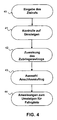
- a destination call for example via the destination call input devices ZEG or a card reader, is supplied to the multigroup control MGS.
- step 41 it checks if it is a transfer journey.
- a feeder elevator A, B, C is selected (step 42).
- an elevator from the terminal elevator group GR2 is used as a feeder elevator, since the elevators DF in this embodiment also approach the boarding platform S1. These elevators DF then drive directly to the transfer floor S4, so that a transfer journey is possible even with such a connection lift.
- a connecting elevator is assigned based on the destinations of the passengers assigned to this feeder elevator while traveling to the transfer floor (step 43).
- the connection elevator (s) assigned to the passengers in the relevant feeder elevator is / are transmitted via a display device (step 44), whereby an announcement of the connection lifts is also possible.
- Fig. 5 shows a detailed procedure of the assignment, in particular it is shown according to which criteria a feeder elevator A, B, C is assigned.
- a new destination call is input from a passenger (step 50). It is determined whether it is a travel destination that requires a change (step 51). If a change is required, in step 53 the query of several parameters.
- the number AZ1 of the intermediate stops in the floors S2-S3 between the boarding floor and the transfer floor S4 is checked and compared with a parameter AZ1MAX. Only if the number AZ1 of the intermediate stops up to the transfer floor S4, including the selected destination, is less than the parameter AZ1MAX, can this feeder elevator be assigned A or B or C for the passenger.
- the multi-group controller MGS In the feeder elevator first checked by the multi-group controller MGS, for example, A, if the number AZ1 is already larger than the parameter AZ1MAX, this feeder elevator A can not be allocated.
- the multigroup control MGS then checks the next possible feeder elevator B and then the feeder elevator C. If the first condition is met, the number of destination floors AZ2 in the upper zone Z2 of the interchange passengers booked for the feeder elevator A, B, C, including the selected destination, determined and compared with the parameter AZ2MAX.
- the feeder elevator checked by the multi-group controller MGS for example, A, can not be assigned to the passenger. In this case, the next cheapest feeder elevator is checked and assigned if it is suitable.
- step 54 the feeder elevator to be selected is transmitted to the passenger in the boarding floor S1 via a display device, for example at the destination call input device ZEG. Afterwards, the journey to the transfer floor S4 takes place (step 55). On the way to the transfer floor S4 lying in the zone Z1 Floors S2 and S3 are approached (step 56). Before the transfer floor S4 is reached (step 57), a connecting elevator DF is selected (step 58).
- the allocation of the connecting elevator D, E, F is supplemented by the following condition in addition to the cost optimization: Only if the number of destinations AZ3 of the connecting elevator, including all destinations of the passengers entering or leaving this connecting elevator, is smaller than a parameter AZ3MAX can a Elevator as connecting elevator to be determined and assigned. Otherwise, the next cheapest elevator is examined and assigned if it is suitable. In the next step 59, the passengers are still informed in the feeder elevator of the terminal elevator to be used. At step 60, the boarding or transfer to the connecting elevator on the transfer floor S4 takes place.
- the elevator is selected which can reach this destination directly (step 52) and a normal one takes place Signaling of the elevator to be used (step 61).
- the above conditions take into account the longer transfer journey and provide clear and comprehensible information about the connecting lifts D-F, which is communicated to the transfer passengers located in the feeder elevator during the feeder journey via display devices.
- the number AAZ of the assignable terminal lifts D, E, F is limited to an automatically controlled minimum, for example 1 to 2 elevators, even with different destination floors.
- the transmission of information in the form of a display or announcement in the arriving on the transfer floor S4 feeder elevator easier and easy to understand.
- This purposeful simplification of the information reduces the likelihood that one of the passengers will miss the connecting elevator. This makes it possible that passengers from a feeder lift in at most two different terminal lifts must change or transfer, so that the information transmission remains simple and thus the passenger flows in the transfer deck not too mixed.
- each transfer passenger in the feeder elevator can be given the information corresponding to each assigned connection lift, for example, destination floor S35, change to elevator D, 8 m to the left, arrival in 22 seconds.
- the information may be, for example: destination floor S56, change to elevator F, 6 m to the right. Arrival in 36 s.
- the transfer passengers of, for example, two feeder lifts may, under certain circumstances, be assigned the same connecting lift, provided that the connecting lift is the best lift for the transfer passengers from both feeder lifts.
- the corresponding investigation of the transfer problem described above is carried out continuously by the transfer control unit USE which communicates continuously with the multigroup control MGS and influences the elevator allocations to the individual destinations as required and operating modes and if necessary also adapts the limiting parameters AZ1MAX, AZ2MAX and AZ3MAX. The result is an optimal travel time for passengers and optimal process management for the operator.
Claims (16)
- Procédé pour commander une installation d'ascenseur à fonctionnement par zones, avec une commande d'appels de destination, selon lequela) un changement d'ascenseur entre des zones (Z1, Z2) est possible à un étage de changement (S4) ;b) avec au moins un groupe d'ascenseurs d'amenée (GR1) et au moins un groupe d'ascenseurs de correspondance (GR2), un transport est réalisé à destination ou en provenance de l'étage de changement (S4), étant précisé que le ou les groupes d'ascenseurs d'amenée (GR1) comprennent plusieurs ascenseurs d'amenée (A, B, C) qui desservent une première zone (Z1) située au-dessous d'un étage de changement (S4) et ledit étage de changement (S4), tandis que le ou les groupes d'ascenseurs de correspondance (GR2) comprennent plusieurs ascenseurs de correspondance (D, E, F) qui desservent l'étage de changement (S4) et les étages (S5-Sn) d'une seconde zone (Z2) situés au-dessus ;c) les destinations sont entrées dans une commande d'appels de destination par l'intermédiaire d'une entrée d'appels de destination etd) le groupe d'ascenseurs d'amenée (GR1) et le groupe d'ascenseurs de correspondance (GR2) sont commandés par une commande multigroupe (MGS),caractérisé en ce que la commande multigroupe (MGS), à l'aide de l'entrée d'appels de destination, affecte un ascenseur d'amenée (A, B, C) en fonction du nombre de destinations de celui-ci dans la première zone (Z1) et en fonction du nombre de destinations des passagers affectés à un ascenseur d'amenée (A, B, C) dans la seconde zone (Z2).
- Procédé selon la revendication 1, caractérisé en ce que lors de l'affectation d'un ascenseur d'amenée (A, B, C), le nombre de passagers avec des destinations différentes dans la première zone (Z1) est limité.
- Procédé selon la revendication 1 ou 2, caractérisé en ce que lors de l'affectation d'un ascenseur d'amenée (A, B, C), le nombre de passagers qui se trouvent dans celui-ci et qui doivent changer d'ascenseur est limité.
- Procédé selon l'une des revendications 1 à 3, caractérisé en ce que lors de l'affectation d'un ascenseur d'amenée (A, B, C), le nombre (AZ1) d'arrêts intermédiaires entre un étage d'embarquement (S1-Sn) et l'étage de changement (S4) est enregistré et est comparé à un paramètre (AZ1MAX) pour le nombre maximal d'arrêts intermédiaires de l'ascenseur d'amenée (A, B, C), et un ascenseur d'amenée (A, B, C) n'est attribué que si le nombre (AZ1) d'arrêts intermédiaires de l'ascenseur d'amenée (A, B, C) est inférieur au paramètre (AZ1MAX).
- Procédé selon la revendication 4, caractérisé en ce que lorsque le nombre maximal d'arrêts intermédiaires (AZ1MAX) entre l'étage d'embarquement (S1-Sn) et l'étage de changement (S4) est atteint, un ascenseur d'amenée (A, B, C) n'est attribué que si l'entrée d'appel de destination émise correspond à un étage (S1-S3) déjà réservé et si la capacité de transport maximale n'est pas dépassée.
- Procédé selon l'une des revendications 1 à 5, caractérisé en ce que lors de l'affectation d'un ascenseur d'amenée (A, B, C), le nombre de passagers avec des destinations différentes dans la seconde zone (Z2) est limité, le nombre (AZ2) d'étages de destination des passagers affectés à l'ascenseur d'amenée (A, B, C) dans la seconde zone (Z2) étant enregistré et comparé à un paramètre (AZ2MAX) pour des destinations différentes dans ladite seconde zone (Z2), et un ascenseur d'amenée (A, B, C) n'étant affecté que si le nombre (AZ2) d'étages de destination différents dans la seconde zone (Z2) de l'ascenseur d'amenée (A, B, C) est inférieur au paramètre (AZ2MAX).
- Procédé selon l'une des revendications 1 à 6, caractérisé en ce que le nombre (AAZ) d'ascenseurs de correspondance (D, E, F) affectables, à l'étage de changement (S4), est limité à un paramètre (AAZMAX) pour les ascenseurs de correspondance (D, E, F) affectables au maximum.
- Procédé selon l'une des revendications 1 à 7, caractérisé en ce que lors de l'affectation de l'ascenseur de correspondance (D, E, F), le nombre (AZ3) de destinations de l'ascenseur de correspondance (D, E, F) affecté est limité, ce nombre (AZ3) de destinations de l'ascenseur de correspondance (D, E, F) étant enregistré et comparé à un paramètre (AZ3MAX) pour le nombre maximal de destinations de l'ascenseur de correspondance (D, E, F), et un ascenseur de correspondance (D, E, F) n'étant affecté que si le nombre (AZ3) de destinations de l'ascenseur de correspondance (D, E, F) est inférieur au paramètre (A23MAX).
- Procédé selon l'une des revendications 1 à 8, caractérisé en ce que la commande multigroupe (MGS) est apte à être influencée à l'aide d'une touche de statut spécial, et lors de l'affectation des ascenseurs d'amenée (A, B, C) et des ascenseurs de correspondance (D, E, F) pour des passagers avec un statut spécial, une durée de changement plus longue ou plus courte est prise en compte.
- Procédé selon l'une des revendications 1 à 9, caractérisé par la signalisation, dans l'ascenseur d'amenée (A, B, C), de l'ascenseur de correspondance (D, E, F) à choisir.
- Procédé selon l'une des revendications 1 à 10, caractérisé en ce que l'ascenseur d'amenée (A, B, C) et l'ascenseur de correspondance (D, E, F) sont affectés en fonction de règles de coût.
- Procédé selon l'une des revendications 1 à 11, caractérisé en ce que les paramètres (AZ1MAX, AZ2MAX, AZ3MAX AAZ-MAX) sont aptes à être adaptés par la commande multigroupe (MGS) en fonction de modes opératoires aptes à être définis au préalable.
- Installation d'ascenseur avec plusieurs groupes d'ascenseurs (GR1, GR2) pourvus d'une commande d'appels de destination, comprenant :a) au moins un groupe d'ascenseurs d'amenée (GR1) avec plusieurs ascenseurs d'amenée (A, B, C), et au moins un groupe d'ascenseurs de correspondance (GR2) avec plusieurs ascenseurs de correspondance (D, E, F), les ascenseurs d'amenée (A, B, C) du groupe d'ascenseurs d'amenée (GR1) desservant une première zone (Z1) d'un bâtiment, les ascenseurs de correspondance (D, E, F) du groupe d'ascenseurs de correspondance (GR2) desservant une seconde zone (Z2) du bâtiment, et les groupes d'ascenseurs (GR1, GR2) desservant conjointement au moins un étage de changement (S4) ;b) des dispositifs d'affichage pour afficher l'ascenseur (A, B, C, D, E, F) à choisir, etc) une commande multigroupe (MGS) pour commander le groupe d'ascenseurs d'amenée (GR1) et le groupe d'ascenseurs de correspondance (GR2),caractérisée en ce qu'après une première entrée d'appel de destination dans la commande d'appels de destination, l'ascenseur d'amenée (A, B, C) le plus avantageux est apte à être choisi dans le groupe d'ascenseurs d'amenée (GR1) en fonction d'un paramètre (AZ1MAX) pour une limite maximale de destinations de l'ascenseur d'amenée (A, B, C) dans la première zone (Z1) et en fonction d'un paramètre (AZ2MAX) pour une limite maximale de destinations dans la seconde zone (Z2).
- Installation d'ascenseur selon la revendication 13, caractérisée en ce que l'ascenseur de correspondance (D, E, F) est apte à être choisi en fonction d'un paramètre (AZ3MAX) qui définit une limite maximale de destinations de l'ascenseur de correspondance (D, E, F) dans la seconde zone (Z2).
- Installation d'ascenseur selon la revendication 13 ou 14, caractérisée en ce que le groupe d'ascenseurs de correspondance (GR2) dessert aussi des destinations (S1) situées au-dessous de l'étage de changement (S4).
- Installation d'ascenseur selon l'une des revendications 13 à 15, caractérisée en ce que lors de l'affectation de l'ascenseur de correspondance (D, E, F), le nombre (AAZ) d'ascenseurs de correspondance (D, E, F) affectables, à l'étage de changement (S4), est apte à être limité à un paramètre (AAZMAX) pour les ascenseurs de correspondance (D, E, F) affectables au maximum.
Priority Applications (1)
| Application Number | Priority Date | Filing Date | Title |
|---|---|---|---|
| EP20040013586 EP1491481B1 (fr) | 2003-06-27 | 2004-06-09 | Méthode de contrôle d'un groupe d'ascenseur avec attribution de zone |
Applications Claiming Priority (3)
| Application Number | Priority Date | Filing Date | Title |
|---|---|---|---|
| EP03405473 | 2003-06-27 | ||
| EP03405473 | 2003-06-27 | ||
| EP20040013586 EP1491481B1 (fr) | 2003-06-27 | 2004-06-09 | Méthode de contrôle d'un groupe d'ascenseur avec attribution de zone |
Publications (2)
| Publication Number | Publication Date |
|---|---|
| EP1491481A1 EP1491481A1 (fr) | 2004-12-29 |
| EP1491481B1 true EP1491481B1 (fr) | 2010-02-17 |
Family
ID=33420613
Family Applications (1)
| Application Number | Title | Priority Date | Filing Date |
|---|---|---|---|
| EP20040013586 Expired - Fee Related EP1491481B1 (fr) | 2003-06-27 | 2004-06-09 | Méthode de contrôle d'un groupe d'ascenseur avec attribution de zone |
Country Status (1)
| Country | Link |
|---|---|
| EP (1) | EP1491481B1 (fr) |
Families Citing this family (4)
| Publication number | Priority date | Publication date | Assignee | Title |
|---|---|---|---|---|
| FI121009B (fi) | 2008-10-24 | 2010-06-15 | Kone Corp | Hissijärjestelmä |
| CN102556783A (zh) * | 2011-07-12 | 2012-07-11 | 江苏镇安电力设备有限公司 | 一种基于分区的电梯交通预测群控方法及其监测实现 |
| DE102014223153A1 (de) | 2014-11-13 | 2016-05-19 | Thyssenkrupp Ag | Verfahren zum Verarbeiten von Rufeingaben durch eine Aufzugsteuerung und Aufzuganlagen zur Durchführung der Verfahren |
| CN113247719B (zh) * | 2021-05-10 | 2024-01-26 | 杭州海康威视数字技术股份有限公司 | 一种电梯群管控系统、方法及电梯业务网关设备 |
Family Cites Families (3)
| Publication number | Priority date | Publication date | Assignee | Title |
|---|---|---|---|---|
| FI85970C (fi) * | 1986-09-24 | 1992-06-25 | Kone Oy | Foerfarande foer koordinering av hissgrupper. |
| CA2251143C (fr) * | 1996-04-03 | 2006-07-11 | Inventio Ag | Systeme de commande pour plusieurs groupes d'ascenseurs a commande d'appel cible |
| US6655501B2 (en) * | 2001-06-29 | 2003-12-02 | Inventio Ag | Method for selection of the most favorable elevator of an elevator installation comprising at least two elevator groups |
-
2004
- 2004-06-09 EP EP20040013586 patent/EP1491481B1/fr not_active Expired - Fee Related
Also Published As
| Publication number | Publication date |
|---|---|
| EP1491481A1 (fr) | 2004-12-29 |
Similar Documents
| Publication | Publication Date | Title |
|---|---|---|
| EP0246395B1 (fr) | Commande d'un groupe d'ascenceur | |
| EP0301178B1 (fr) | Système de commande d'ascenseur | |
| EP1565396B1 (fr) | Procede pour commander un systeme d'ascenseurs et systeme d'ascenseurs pour mettre en oeuvre le procede | |
| EP1276691B1 (fr) | Commande d'appel cible pour ascenseurs | |
| EP1418147B1 (fr) | Contrôleur pour ascenseur avec cabine avec plusieurs compartiments | |
| EP0312730B1 (fr) | Commande de groupe pour ascenceurs avec commande des cabines dépendant de leur charge | |
| EP0440967B1 (fr) | Commande de groupes pour ascenseurs avec distribution directe d'appels d'une entrée d'appels située sur l'étage | |
| EP3206982B1 (fr) | Procédé de fonctionnement d'un système de transport et système de transport correspondant | |
| EP0891291B1 (fr) | Systeme de commande pour plusieurs groupes d'ascenseurs a commande d'appel cible | |
| EP1619157B2 (fr) | Système d'ascenseurs avec cabines indépendantes et méthode pour contrôler leur déplacement | |
| EP0199015B1 (fr) | Dispositif de commande d'ascenseur en fonction de la charge | |
| EP0091554B1 (fr) | Commande d'un groupe d'ascenseurs comportant un dispositif pour la commande d'une pointe de trafic descendante | |
| EP0459169B1 (fr) | Commande de groupes pour ascenseurs avec deux cabines superposées avec distribution directe d'appels | |
| EP0356731A1 (fr) | Commande groupée avec attribution immédiate des appels | |
| WO2016135090A1 (fr) | Procédé permettant de faire fonctionner un système d'ascenseur comportant plusieurs cages et plusieurs cabines | |
| EP0624540B1 (fr) | Système d'ascenseur pour opération à zones | |
| US7117980B2 (en) | Method and apparatus for controlling an elevator installation with zoning and an interchange floor | |
| DE3732204A1 (de) | Verfahren zur koordination des verkehrs von aufzuggruppen in gebaeuden mit umsteigetage | |
| EP0134892B1 (fr) | Commande d'un groupe d'ascenseurs pour cabines à compartiments doubles | |
| EP0378834B1 (fr) | Commande d'un groupe d'ascenseurs avec attribution immédiate des appels | |
| EP0242520B1 (fr) | Dispositif d'affichage pour ascenseur | |
| EP0308590B1 (fr) | Commande d'un groupe d'ascenceurs avec attribution immédiate des appels | |
| EP1491481B1 (fr) | Méthode de contrôle d'un groupe d'ascenseur avec attribution de zone | |
| EP2651804B1 (fr) | Système d'ascenseur économe en énergie | |
| EP1270486B1 (fr) | Méthode pour sélectionner le parcours optimal, changements de cabines inclus, parmis plusieurs groupes d'ascenseurs |
Legal Events
| Date | Code | Title | Description |
|---|---|---|---|
| PUAI | Public reference made under article 153(3) epc to a published international application that has entered the european phase |
Free format text: ORIGINAL CODE: 0009012 |
|
| AK | Designated contracting states |
Kind code of ref document: A1 Designated state(s): AT BE BG CH CY CZ DE DK EE ES FI FR GB GR HU IE IT LI LU MC NL PL PT RO SE SI SK TR |
|
| AX | Request for extension of the european patent |
Extension state: AL HR LT LV MK |
|
| 17P | Request for examination filed |
Effective date: 20050617 |
|
| AKX | Designation fees paid |
Designated state(s): DE FR GB |
|
| 17Q | First examination report despatched |
Effective date: 20060929 |
|
| GRAP | Despatch of communication of intention to grant a patent |
Free format text: ORIGINAL CODE: EPIDOSNIGR1 |
|
| GRAS | Grant fee paid |
Free format text: ORIGINAL CODE: EPIDOSNIGR3 |
|
| GRAA | (expected) grant |
Free format text: ORIGINAL CODE: 0009210 |
|
| AK | Designated contracting states |
Kind code of ref document: B1 Designated state(s): DE FR GB |
|
| REG | Reference to a national code |
Ref country code: GB Ref legal event code: FG4D Free format text: NOT ENGLISH |
|
| REF | Corresponds to: |
Ref document number: 502004010757 Country of ref document: DE Date of ref document: 20100401 Kind code of ref document: P |
|
| PLBE | No opposition filed within time limit |
Free format text: ORIGINAL CODE: 0009261 |
|
| STAA | Information on the status of an ep patent application or granted ep patent |
Free format text: STATUS: NO OPPOSITION FILED WITHIN TIME LIMIT |
|
| 26N | No opposition filed |
Effective date: 20101118 |
|
| REG | Reference to a national code |
Ref country code: FR Ref legal event code: PLFP Year of fee payment: 13 |
|
| REG | Reference to a national code |
Ref country code: FR Ref legal event code: PLFP Year of fee payment: 14 |
|
| REG | Reference to a national code |
Ref country code: FR Ref legal event code: PLFP Year of fee payment: 15 |
|
| PGFP | Annual fee paid to national office [announced via postgrant information from national office to epo] |
Ref country code: DE Payment date: 20190619 Year of fee payment: 16 |
|
| PGFP | Annual fee paid to national office [announced via postgrant information from national office to epo] |
Ref country code: FR Payment date: 20190619 Year of fee payment: 16 |
|
| PGFP | Annual fee paid to national office [announced via postgrant information from national office to epo] |
Ref country code: GB Payment date: 20190619 Year of fee payment: 16 |
|
| REG | Reference to a national code |
Ref country code: DE Ref legal event code: R119 Ref document number: 502004010757 Country of ref document: DE |
|
| GBPC | Gb: european patent ceased through non-payment of renewal fee |
Effective date: 20200609 |
|
| PG25 | Lapsed in a contracting state [announced via postgrant information from national office to epo] |
Ref country code: FR Free format text: LAPSE BECAUSE OF NON-PAYMENT OF DUE FEES Effective date: 20200630 Ref country code: GB Free format text: LAPSE BECAUSE OF NON-PAYMENT OF DUE FEES Effective date: 20200609 |
|
| PG25 | Lapsed in a contracting state [announced via postgrant information from national office to epo] |
Ref country code: DE Free format text: LAPSE BECAUSE OF NON-PAYMENT OF DUE FEES Effective date: 20210101 |