EP0308590B1 - Group control for lifts affording instantaneous attribution of destination calls - Google Patents
Group control for lifts affording instantaneous attribution of destination calls Download PDFInfo
- Publication number
- EP0308590B1 EP0308590B1 EP88110006A EP88110006A EP0308590B1 EP 0308590 B1 EP0308590 B1 EP 0308590B1 EP 88110006 A EP88110006 A EP 88110006A EP 88110006 A EP88110006 A EP 88110006A EP 0308590 B1 EP0308590 B1 EP 0308590B1
- Authority
- EP
- European Patent Office
- Prior art keywords
- call
- storey
- input
- store
- allocation
- Prior art date
- Legal status (The legal status is an assumption and is not a legal conclusion. Google has not performed a legal analysis and makes no representation as to the accuracy of the status listed.)
- Expired - Lifetime
Links
- 210000000352 storage cell Anatomy 0.000 claims abstract 7
- 101100325756 Arabidopsis thaliana BAM5 gene Proteins 0.000 claims description 16
- 101150046378 RAM1 gene Proteins 0.000 claims description 16
- 101100476489 Rattus norvegicus Slc20a2 gene Proteins 0.000 claims description 16
- RRLHMJHRFMHVNM-BQVXCWBNSA-N [(2s,3r,6r)-6-[5-[5-hydroxy-3-(4-hydroxyphenyl)-4-oxochromen-7-yl]oxypentoxy]-2-methyl-3,6-dihydro-2h-pyran-3-yl] acetate Chemical compound C1=C[C@@H](OC(C)=O)[C@H](C)O[C@H]1OCCCCCOC1=CC(O)=C2C(=O)C(C=3C=CC(O)=CC=3)=COC2=C1 RRLHMJHRFMHVNM-BQVXCWBNSA-N 0.000 claims description 10
- 102100031584 Cell division cycle-associated 7-like protein Human genes 0.000 claims description 8
- 101000777638 Homo sapiens Cell division cycle-associated 7-like protein Proteins 0.000 claims description 8
- 101100328887 Caenorhabditis elegans col-34 gene Proteins 0.000 claims description 4
- 230000015654 memory Effects 0.000 abstract description 57
- 238000000034 method Methods 0.000 description 3
- 230000000694 effects Effects 0.000 description 2
- 230000005540 biological transmission Effects 0.000 description 1
- 108010066114 cabin-2 Proteins 0.000 description 1
- 239000004020 conductor Substances 0.000 description 1
- 230000008878 coupling Effects 0.000 description 1
- 238000010168 coupling process Methods 0.000 description 1
- 238000005859 coupling reaction Methods 0.000 description 1
- 230000006870 function Effects 0.000 description 1
- 230000001960 triggered effect Effects 0.000 description 1
Images

Classifications
-
- B—PERFORMING OPERATIONS; TRANSPORTING
- B66—HOISTING; LIFTING; HAULING
- B66B—ELEVATORS; ESCALATORS OR MOVING WALKWAYS
- B66B1/00—Control systems of elevators in general
- B66B1/24—Control systems with regulation, i.e. with retroactive action, for influencing travelling speed, acceleration, or deceleration
- B66B1/2408—Control systems with regulation, i.e. with retroactive action, for influencing travelling speed, acceleration, or deceleration where the allocation of a call to an elevator car is of importance, i.e. by means of a supervisory or group controller
- B66B1/2458—For elevator systems with multiple shafts and a single car per shaft
-
- B—PERFORMING OPERATIONS; TRANSPORTING
- B66—HOISTING; LIFTING; HAULING
- B66B—ELEVATORS; ESCALATORS OR MOVING WALKWAYS
- B66B2201/00—Aspects of control systems of elevators
- B66B2201/10—Details with respect to the type of call input
- B66B2201/103—Destination call input before entering the elevator car
-
- B—PERFORMING OPERATIONS; TRANSPORTING
- B66—HOISTING; LIFTING; HAULING
- B66B—ELEVATORS; ESCALATORS OR MOVING WALKWAYS
- B66B2201/00—Aspects of control systems of elevators
- B66B2201/20—Details of the evaluation method for the allocation of a call to an elevator car
- B66B2201/211—Waiting time, i.e. response time
-
- B—PERFORMING OPERATIONS; TRANSPORTING
- B66—HOISTING; LIFTING; HAULING
- B66B—ELEVATORS; ESCALATORS OR MOVING WALKWAYS
- B66B2201/00—Aspects of control systems of elevators
- B66B2201/20—Details of the evaluation method for the allocation of a call to an elevator car
- B66B2201/222—Taking into account the number of passengers present in the elevator car to be allocated
Definitions
- the invention relates to a group control for elevators with immediate assignment of destination calls, with call registration devices arranged on the floors, by means of which calls for desired destination floors can be entered, with the storeys and car call store memories assigned to the elevators, which are connected to the call registration devices, in which case Input of calls on a floor a call characterizing the input floor is stored in the floor call memory and the calls characterizing the target floors are stored in the car call memory, and with load measuring devices provided in the cars of the elevator group, with each elevator assigned to the group, each indicating the floor of a possible stopping Selectors, assigned to each elevator of the group, having at least one position for each floor and having a device by means of which the calls entered enter the cars d he elevator group can be allocated, according to the preamble of claim 1.
- the car call memory of an elevator of this group control consists of a first memory which already contains allocated car calls and further memories assigned to the floors, in which the calls which have been entered on the relevant floors for desired destination floors and have not yet been allocated to a car are stored.
- a device by means of which the entered calls are allocated to the cabins of the elevator group has a computer in the form of a microprocessor and one Comparison device.
- the computer calculates the time lost by waiting passengers from at least the distance between the floor and the cabin position indicated by a selector, the intermediate stops to be expected within this distance and the load in the cabin Total proportional to the floors and in the cabin. If the first scanner encounters an as yet unallocated floor call, then the calls entered on this floor for the desired destination floors and stored in the further memories of the cabin call memory must also be taken into account. An additional sum proportional to the time lost by the passengers in the cabin is therefore determined and a total sum is formed. This total, also called operating costs, is stored in a cost memory.
- the operating costs of all elevators are compared with one another by means of the comparison device, an allocation instruction being stored in an allocation memory of the elevator with the lowest operating costs, which indicates the floor to which the relevant car is optimally assigned in terms of time.
- the service costs are calculated immediately after the entry of a call for a desired destination floor, the subsequent assignment of the call to the cabin with the cheapest service costs being carried out by means of the subsequent comparison.
- a call assigned to a particular car for the first time can be assigned to another car if it has not yet been transferred to the drive control of the elevator in question. This allows passengers waiting for a cabin on one floor Difficulties arise because it is not possible to signal the ultimately allocated cabin in good time.
- the advantages achieved by the invention are that the relevant cabin can be signaled immediately after the first assignment of a call, so that there is sufficient time for the passengers waiting on one floor to recognize the display and to go to the signaled elevator in good time.
- a and B designate two elevators of an elevator group, with each elevator driving a car 2 guided in an elevator shaft 1 by a conveyor 3 via a conveyor cable 4 and serving thirteen floors E0 to E12.
- the carrier 2 is controlled by a drive control known from EP-B-0 026 406, the setpoint generation, the control functions and the start of the stop being implemented by means of a microcomputer system 5 which is connected to measuring and actuating elements 6 of the drive control.
- the microcomputer system 5 also calculates from elevator-specific parameters a sum corresponding to the average waiting time of all passengers, also called service costs, which is used as the basis for the call allocation process.
- the cabin 2 has a load measuring device 7, which is also connected to the microcomputer system 5.
- Call registering devices 8 in the form of 10-keyboards are provided on the floors, by means of which calls can be entered for trips to the desired destination floors.
- the call registration devices 8 are connected via an address bus AB and a data input conductor CRUIN to the microcomputer system 5 and to an input device 9 which has become known from EP-B-0 062 141.
- the call registration devices 8 can be assigned to more than one elevator of the group, wherein, for example, those of the elevator A are connected to the microcomputer system 5 and the input device 9 of the elevator B via coupling links in the form of multiplexers 10.
- the microcomputer systems 5 of the individual elevators in the group are connected to one another via a comparison device 11 known from EP-B-0 050 304 and a party line transmission system 12 known from EP-B-0 050 305 and form together with the call registration and input devices 8, 9 in this way a group control which structurally corresponds to a group control described in EP-A-0 246 395.
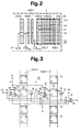
- the microcomputer system 5 shown partially schematically in FIG. 2 has a floor call memory RAM1, a car call memory RAM2, a cost memory RAM4, an allocation memory RAM5, a first and second scanner R1 and R2 and a selector R3 on.
- the car call memory RAM2 consists of a first memory RAM2 ', which has memory locations corresponding to the number of floors, in which calls which have already been allocated are stored.
- the car call memory RAM2 also has further memories RAM2.0, RAM2.1 Vietnamese RAM2.12 assigned to the floors E0, E1 .... E12, which also have memory locations corresponding to the number of floors into which the calls entered into the relevant floors are transmitted which have not yet been assigned to a specific car.
- the self-holding circuit 13 consists of a first, second, third and fourth AND gate 14, 15, 16 and 17 each having two inputs, a first OR gate 18 having two inputs, and a second, three inputs having OR gate 19 and two NOT gates 20 and 21.
- 22 and 23 designate memory cells of the allocation memory RAM5 and the storey call memory RAM1, whose clock connections C, as is known, are connected via AND gates 24, 25 to write and address connections we, a are, the address port a with the second Scanner R2 (Fig.2) is linked.
- the data outputs Q of the memory cells 22, 23 are connected via the NOT gates 20, 21 to the inputs of the first AND gate 14, the output of which via the one input of the first OR gate 18 to the data input D of the memory cell 22 of the allocation memory RAM5 and via one input of the second OR gate 19 is connected to the data input D of the memory cell 23 of the storey call memory RAM1.
- the data output Q the memory cell 23 is also connected via the NOT gate 21 to one input of the fourth AND gate 17, the output of which is connected to the other input of the first OR gate 18.
- the other inputs of the second and fourth AND elements 15 and 17 are supplied with an assignment instruction Co which can be generated during a comparison process in accordance with the aforementioned EP-B-0 050 304.
- the output of the first AND gate 14 is also connected to one input of the third AND gate 16, the other input a 'of which is connected to the selector R3 (FIG. 2) and the output of which is connected to the drive control of the elevator in question.
- the self-holding circuit 13 can be formed by the microprocessor of the microcomputer system 5 on the basis of a program at each position of the second scanner R2 (FIG. 2) for the floor in question.
- a floor call for floor E5 is stored in the floor call memory RAM1 and the calls for the destination floors E7 and E9 are stored in the further memory RAM2.5. It may now be assumed that in the first comparison after the call input, the floor call E5 is assigned to the elevator A, the calls E7 and E9 stored in the further memory RAM2.5 being evident from the aforementioned EP-A-0 246 395 the first memory RAM2 'of the car call memory RAM2 are transferred.
Landscapes
- Engineering & Computer Science (AREA)
- Automation & Control Theory (AREA)
- Elevator Control (AREA)
- Indicating And Signalling Devices For Elevators (AREA)
- Maintenance And Inspection Apparatuses For Elevators (AREA)
- Table Devices Or Equipment (AREA)
- Display Devices Of Pinball Game Machines (AREA)
- Electrophonic Musical Instruments (AREA)
Abstract
Description
Die Erfindung betrifft eine Gruppensteuerung für Aufzüge mit Sofortzuteilung von Zielrufen, mit auf den Stockwerken angeordneten Rufregistriereinrichtungen, mittels welchen Rufe für gewünschte Zielstockwerke eingegeben werden können, mit den Aufzügen der Gruppe zugeordneten Stockwerk- und Kabinenrufspeichern, die mit den Rufregistriereinrichtungen verbunden sind, wobei bei der Eingabe von Rufen auf einem Stockwerk ein das Eingabestockwerk kennzeichnender Ruf im Stockwerkrufspeicher gespeichert wird und die die Zielstockwerke kennzeichnenden Rufe im Kabinenrufspeicher gespeichert werden, und mit in den Kabinen der Aufzugsgruppe vorgesehenen Lastmesseinrichtungen, mit jedem Aufzug der Gruppe zugeordneten, jeweils das Stockwerk eines möglichen Anhaltens anzeigenden Selektoren, mit jedem Aufzug der Gruppe zugeordneten, für jedes Stockwerk mindestens eine Stellung aufweisenden ersten und zweiten Abtastern und mit einer Einrichtung, mittels welcher die eingegebenen Rufe den Kabinen der Aufzugsgruppe zugeteilt werden, gemäss Oberbegriff des Patentanspruches 1.The invention relates to a group control for elevators with immediate assignment of destination calls, with call registration devices arranged on the floors, by means of which calls for desired destination floors can be entered, with the storeys and car call store memories assigned to the elevators, which are connected to the call registration devices, in which case Input of calls on a floor a call characterizing the input floor is stored in the floor call memory and the calls characterizing the target floors are stored in the car call memory, and with load measuring devices provided in the cars of the elevator group, with each elevator assigned to the group, each indicating the floor of a possible stopping Selectors, assigned to each elevator of the group, having at least one position for each floor and having a device by means of which the calls entered enter the cars d he elevator group can be allocated, according to the preamble of
Bei einer derartigen mit der EP-A- 0 246 395 bekannt gewordenen Gruppensteuerung können die Zuordnungen der Kabinen zu den eingegebenen Rufen zeitlich optimiert werden. Der Kabinenrufspeicher eines Aufzuges dieser Grupensteuerung besteht aus einem ersten, bereits zugeteilte Kabinenrufe enthaltenden Speicher und den Stockwerken zugeordneten weiteren Speichern, in welchen die auf den betreffenden Stockwerken für gewünschte Zielstockwerke eingegebenen, noch nicht einer Kabine zugeteilten Rufe gespeichert sind. Eine Einrichtung, mittels welcher die eingegebenen Rufe den Kabinen der Aufzugsgruppe zugeteilt werden, weist einen Rechner in Form eines Mikroprozessors und eine Vergleichseinrichtung auf. Der Rechner errechnet während eines Abtastzyklusses eines ersten Abtasters einer Abtasteinrichtung bei jedem Stockwerk aus mindestens der Distanz zwischen dem Stockwerk und der von einem Selektor angezeigten Kabinenposition, den innerhalb dieser Distanz zu erwartenden Zwischenhalten und der Last in der Kabine, eine den Zeitverlusten von wartenden Fahrgästen auf den Stockwerken und in der Kabine proportionale Summe. Treffen die ersten Abtaster auf einen noch nicht zugeteilten Stockwerkruf, so müssen die auf diesem Stockwerk für gewünschte Zielstockwerke eingegebenen, in den weiteren Speichern des Kabinenrufspeichers gespeicherten Rufe mit in Rechnung gestellt werden. Es wird daher eine zusätzliche, den Zeitverlusten der Fahrgäste in der Kabine proportionale Summe ermittelt und eine Gesamtsumme gebildet. Diese, auch Bedienungskosten genannte Gesamtsumme, wird in einem Kostenspeicher gespeichert. Während eines Abtastzyklusses eines zweiten Abtasters der Abtasteinrichtung werden die Bedienungskosten aller Aufzüge mittels der Vergleichseinrichtung miteinander verglichen, wobei jeweils in einem Zuteilungsspeicher des Aufzuges mit den geringsten Bedienungskosten eine Zuteilungsanweisung gespeichert wird, die dasjenige Stockwerk bezeichnet, dem die betreffende Kabine zeitlich optimal zugeordnet ist.With such a group control, which has become known from EP-A-0 246 395, the assignments of the cars to the entered calls can be optimized in terms of time. The car call memory of an elevator of this group control consists of a first memory which already contains allocated car calls and further memories assigned to the floors, in which the calls which have been entered on the relevant floors for desired destination floors and have not yet been allocated to a car are stored. A device by means of which the entered calls are allocated to the cabins of the elevator group has a computer in the form of a microprocessor and one Comparison device. During a scanning cycle of a first scanner of a scanning device on each floor, the computer calculates the time lost by waiting passengers from at least the distance between the floor and the cabin position indicated by a selector, the intermediate stops to be expected within this distance and the load in the cabin Total proportional to the floors and in the cabin. If the first scanner encounters an as yet unallocated floor call, then the calls entered on this floor for the desired destination floors and stored in the further memories of the cabin call memory must also be taken into account. An additional sum proportional to the time lost by the passengers in the cabin is therefore determined and a total sum is formed. This total, also called operating costs, is stored in a cost memory. During a scanning cycle of a second scanner of the scanning device, the operating costs of all elevators are compared with one another by means of the comparison device, an allocation instruction being stored in an allocation memory of the elevator with the lowest operating costs, which indicates the floor to which the relevant car is optimally assigned in terms of time.
Bei dieser Steuerung werden unmittelbar nach der Eingabe eines Rufes für ein gewünschtes Zielstockwerk die Bedienungkosten errechnet, wobei mittels des anschliessenden Vergleiches die sofortige Zuteilung des Rufes an die Kabine mit den günstigsten Bedienungskosten erfolgt. Da jedoch bei Änderungen der Verkehrssituation und entsprechenden Neuberechnungen der Bedienungskosten andere Vergleichsergebnisse entstehen können, kann ein erstmalig einer bestimmten Kabine zugeteilter Ruf einer anderen Kabine zugeteilt werden, wenn er noch nicht der Antriebssteuerung des betreffenden Aufzuges übergeben wurde. Hierbei können für die auf einem Stockwerk auf eine Kabine wartenden Fahrgäste Schwierigkeiten entstehen, da es nicht möglich ist, die letztendlich zugeteilte Kabine rechtzeitig genug zu signalisieren.With this control, the service costs are calculated immediately after the entry of a call for a desired destination floor, the subsequent assignment of the call to the cabin with the cheapest service costs being carried out by means of the subsequent comparison. However, since changes in the traffic situation and corresponding recalculation of the operating costs may result in different comparison results, a call assigned to a particular car for the first time can be assigned to another car if it has not yet been transferred to the drive control of the elevator in question. This allows passengers waiting for a cabin on one floor Difficulties arise because it is not possible to signal the ultimately allocated cabin in good time.
Es ist daher Aufgabe der Erfindung, eine Gruppensteuerung gemäss Oberbegriff zu schaffen, bei welcher das Rufzuteilungsverfahren eine rechtzeitige Anzeige der zugeteilten Kabine ermöglicht.It is therefore an object of the invention to provide a group control according to the preamble, in which the call allocation method enables the allocated cabin to be displayed in good time.
Diese Aufgabe wird durch die im Patentanspruch 1 gekennzeichnete Erfindung gelöst. Hierbei ist je Aufzug ein Selbsthalte-Schaltkreis vorgesehen, der bewirkt, dass ein erstmalig zugeteilter Ruf einer Kabine zugeteilt bleibt, bis er von der betreffenden Antriebssteuerung übernommen wird.This object is achieved by the invention characterized in
Die mit der Erfindung erzielten Vorteile liegen darin, dass sofort nach der erstmaligen Zuteilung eines Rufes die betreffende Kabine signalisiert werden kann, so dass für die auf einem Stockwerk wartenden Fahrgäste genügend Zeit verbleibt, die Anzeige zu erkennen und sich rechtzeitig zum signalisierten Aufzug zu begeben.The advantages achieved by the invention are that the relevant cabin can be signaled immediately after the first assignment of a call, so that there is sufficient time for the passengers waiting on one floor to recognize the display and to go to the signaled elevator in good time.
Im folgenden wird die Erfindung anhand eines auf der Zeichnung dargestellten Ausführungsbeispieles näher erläutert. Es zeigen:
- Fig. 1
- eine schematische Darstellung der erfindungsgemässen Gruppensteuerung für zwei Aufzüge einer Aufzugsgruppe,
- Fig. 2
- eine schematische Darstellung eines Teiles eines einem Aufzug zugeordneten Mikrocomputersystems der Gruppensteuerung gemäss Fig. 1, und
- Fig. 3
- eine schematische Darstellung eines einem Aufzug zugeordneten Selbsthalte-Schaltkreises der Gruppensteuerung gemäss Fig. 1.
- Fig. 1
- 1 shows a schematic representation of the group control according to the invention for two elevators of an elevator group,
- Fig. 2
- 1 shows a schematic illustration of a part of a microcomputer system of the group control assigned to an elevator, and
- Fig. 3
- 2 shows a schematic illustration of a self-holding circuit of the group control system assigned to an elevator according to FIG. 1.
In der Fig.1 sind mit A und B zwei Aufzüge einer Aufzugsgruppe bezeichnet, wobei bei jedem Aufzug eine in einem Aufzugsschacht 1 geführte Kabine 2 von einer Fördermaschine 3 über ein Förderseil 4 angetrieben wird und dreizehn Stockwerke E0 bis E12 bedient werden. Die Fördermaschine 2 wird von einer aus der EP-B- 0 026 406 bekannten Antriebssteuerung gesteuert, wobei die Sollwerterzeugung, die Regelfunktionen und die Stoppeinleitung mittels eines Mikrocomputersystems 5 realisiert werden, das mit Mess- und Stellgliedern 6 der Antriebssteuerung in Verbindung steht. Das Mikrocomputersystem 5 berechnet ausserdem aus aufzugsspezifischen Parametern eine der durchschnittlichen Wartezeit aller Fahrgäste entsprechende Summe, auch Bedienungskosten genannt, die dem Rufzuteilungsverfahren zugrunde gelegt wird. Die Kabine 2 weist eine Lastmesseinrichtung 7 auf, die ebenfalls mit dem Mikrocomputersystem 5 verbunden ist. Auf den Stockwerken sind Rufregistriereinrichtungen 8 in Form von 10er-Tastaturen vorgesehen, mittels welchen Rufe für Fahrten zu gewünschten Zielstockwerken eingegeben werden können. Die Rufregistriereinrichtungen 8 sind über einen Adressenbus AB und einen Dateneingabeleiter CRUIN mit dem Mikrocomputersystem 5 und einer mit der EP-B- 0 062 141 bekanntgewordenen Eingabeeinrichtung 9 verbunden. Die Rufregistriereinrichtungen 8 können mehr als einem Aufzug der Gruppe zugeordnet sein, wobei beispielsgemäss diejenigen des Aufzuges A über Koppelglieder in Form von Multiplexern 10 mit dem Mikrocomputersystem 5 und der Eingabeeinrichtung 9 des Aufzuges B in Verbindung stehen. Die Mikrocomputersysteme 5 der einzelnen Aufzüge der Gruppe sind über eine aus der EP-B- 0 050 304 bekannte Vergleichseinrichtung 11 und ein aus der EP-B- 0 050 305 bekanntes Partyline-Übertragungssystem 12 miteinander verbunden und bilden zusammen mit den Rufregistrier- und Eingabeeinrichtungen 8, 9 in dieser Weise eine Gruppensteuerung, die strukturell mit einer in der EP-A- 0 246 395 beschriebenen Gruppensteuerung übereinstimmt.In FIG. 1, A and B designate two elevators of an elevator group, with each elevator driving a
Mit 13 ist ein Selbsthalte-Schaltkreis bezeichnet, der mit Komponenten des Mikrocomputersystems 5 verbunden ist und nachstehend anhand der Fig.3 näher erläutert wird.13 denotes a self-holding circuit, which is connected to components of the
Das in der Fig.2 teilweise schematisch dargestellte Mikrocomputersystem 5 weist gemäss vorstehend genannter EP-A- 0 246 395 einen Stockwerkrufspeicher RAM1, einen Kabinenrufspeicher RAM2, einen Kostenspeicher RAM4, einen Zuteilungsspeicher RAM5, einen ersten und zweiten Abtaster R1 und R2 und einen Selektor R3 auf. Der Kabinenrufspeicher RAM2 besteht aus einem ersten Speicher RAM2', welcher der Anzahl der Stockwerke entsprechende Speicherplätze aufweist, in dem bereits zugeteilte Rufe gespeichert sind. Der Kabinenrufspeicher RAM2 weist ausserdem weitere, den Stockwerken E0, E1....E12 zugeordnete Speicher RAM2.0, RAM2.1.....RAM2.12 auf, die ebenfalls der Anzahl der Stockwerke entsprechende Speicherplätze besitzen, in welche die an den betreffenden Stockwerken eingegebenen Rufe übertragen werden, die noch keiner bestimmten Kabine zugeteilt sind. So werden gemäss Beispiel Fig.2 auf dem Stockwerk E5 eingegebene Rufe für die Stockwerke E7 und E9 in den weiteren Speicher RAM2.5 übertragen, wobei gleichzeitig im Stockwerkrufspeicher RAM1 ein Ruf für Stockwerk E5 gespeichert wird. Entsprechend der üblichen logischen Symbolik sind die gespeicherten Rufe in der Fig.2 mit "1" gekennzeichnet.According to EP-A-0 246 395 mentioned above, the
Gemäss Fig.3 besteht der Selbsthalte-Schaltkreis 13 aus einem ersten, zweiten, dritten und vierten je zwei Eingänge aufweisenden UND-Glied 14, 15, 16 und 17, einem ersten, zwei Eingänge aufweisenden ODER-Glied 18, einem zweiten, drei Eingänge aufweisenden ODER-Glied 19 und zwei NICHT-Gliedern 20 und 21. Mit 22 und 23 sind Speicherzellen des Zuteilungsspeichers RAM5 und des Stockwerkrufspeichers RAM1 bezeichnet, deren Taktanschlüsse C wie bekannt über UND-Glieder 24, 25 mit Schreib- und Adressenanschlüssen we, a verbunden sind, wobei der Adressenanschluss a mit dem zweiten Abtaster R2 (Fig.2) verknüpft ist. Die Datenausgänge
Die Arbeitsweise der vorstehend beschriebenen Gruppensteuerung wird im folgenden an Hand der Fig.2 und 3 näher erläutert:
Gemäss der eingangs genannten EP-A- 0 246 395 wird bei Eingabe eines Rufes bei allen Aufzügen der Gruppe eine Bedienungskostenberechnung ausgelöst und bei jedem vom ersten Abtaster R1 bezeichneten Stockwerk durchgeführt. Die hierbei errechneten Bedienungskosten werden pro Stockwerk im Kostenspeicher RAM4 gespeichert. Wie weiterhin aus vorgenannter Druckschrift bekannt, wird nach Ablauf eines Kostenberechnungszyklusses ein Kostenvergleichszyklus durchgeführt. Hierbei werden die in den Kostenspeichern RAM4 aller Aufzüge gespeicherten Bedienungskosten der jeweils vom zweiten Abtaster R2 bezeichneten Stockwerke miteinander verglichen und der betreffende Ruf derjenigen Kabine zugeteilt, welche die kleinsten Bedienungskosten aufweist.The mode of operation of the group control described above is explained in more detail below with reference to FIGS. 2 and 3:
According to EP-A-0 246 395 mentioned at the outset, when a call is entered, an operating cost calculation is triggered for all elevators in the group and is carried out on each floor designated by the first scanner R1. The operating costs calculated here are stored in the RAM4 cost memory per floor. As is also known from the aforementioned publication, a cost comparison cycle is carried out after the end of a cost calculation cycle. In this case, the operating costs of the floors designated by the second scanner R2 stored in the cost memories RAM4 of all elevators are compared with one another and the relevant call is allocated to the cabin that has the lowest operating costs.
Bei der Eingabe von Rufen, beispielsweise auf dem Stockwerk E5 für die Zielstockwerke E7 und E9 werden im Stockwerkrufspeicher RAM1 ein Stockwerkruf für Stockwerk E5 und im weiteren Speicher RAM2.5 die Rufe für die Zielstockwerke E7 und E9 gespeichert. Es möge nun angenommen sein, dass beim ersten Vergleich nach der Rufeingabe der Stockwerkruf E5 dem Aufzug A zugeteilt wird, wobei wie aus der eingangs genannten EP-A- 0 246 395 ersichtlich, die im weiteren Speicher RAM2.5 gespeicherten Rufe E7 und E9 in den ersten Speicher RAM2' des Kabinenrufspeichers RAM2 übertragen werden. Beim Vergleich von Stockwerk E5 wird durch die vom Abtaster R2 erzeugte Adresse a=1, so dass mit we=1 und a=1 an den Eingängen des UND-Gliedes 24 und Co=1 am anderen Eingang des vierten UND-Gliedes 17 die dem Stockwerk E5 zugeordnete Speicherzelle 22 des Zuteilungsspeichers RAM5 des Aufzuges A gesetzt und deren Datenausgang Q=0 wird. Da bei einem gespeicherten Ruf für Stockwerk E5 der Datenausgang Q der betreffenden Speicherzelle 23 des Stockwerkrufspeichers RAM1 ebenfalls "0" ist, werden der Ausgang des ersten UND-Gliedes 14 und damit auch der eine Eingang des ersten ODER-Gliedes 18 auf "1" gesetzt. Es soll weiterhin angenommen sein, dass der Ruf für Stockwerk E5 noch vor Übergabe an die Antriebssteuerung des Aufzuges A durch einen neuen Vergleich dem Aufzug B zugeteilt wird. In diesem Falle wird zum Zwecke des Löschens der betreffenden Speicherzelle 22 des Zuteilungsspeichers RAM5 für Aufzug A eine Zuteilungsanweisung Co=0 erzeugt, die sich jedoch nicht auswirken kann, da der Dateneingang D der Speicherzelle 22 über den einen Eingang des ODER-Gliedes 18 auf "1" gehalten wird. Auf diese Weise kann der bei einem ersten Vergleich dem Aufzug A zugeteilte Stockwerkruf E5 keinem anderen Aufzug der Gruppe mehr zugeteilt werden. Liegt der zugeteilte Ruf in Fahrtrichtung der Kabine 2 des Aufzuges A und schaltet der Selektor R3 auf die Adresse des Stockwerkes E5, so wird a'=1, womit am Ausgang des dritten UND-Gliedes 16 ein Signal "1" auftritt, das von der Antriebssteuerung des Aufzuges A als Fahrbefehl zum Stockwerk E5 interpretiert wird.When calls are entered, for example on the floor E5 for the destination floors E7 and E9, a floor call for floor E5 is stored in the floor call memory RAM1 and the calls for the destination floors E7 and E9 are stored in the further memory RAM2.5. It may now be assumed that in the first comparison after the call input, the floor call E5 is assigned to the elevator A, the calls E7 and E9 stored in the further memory RAM2.5 being evident from the aforementioned EP-A-0 246 395 the first memory RAM2 'of the car call memory RAM2 are transferred. When comparing floor E5, the address generated by the scanner R2 a = 1, so that with we = 1 and a = 1 at the inputs of the
Bei der erstmaligen Zuteilung des Stockwerkes E5 an den Aufzug A werden die Zuteilungsanweisungen Co für die anderen Aufzüge der Gruppe "0". Hierbei wird bei diesen Aufzügen bei we=1 und a=1 an den Eingängen des UND-Gliedes 25 und Co=0 am anderen Eingang des zweiten UND-Gliedes 15 die betreffende Speicherzelle 23 des Stockwerkrufspeichers RAM1 gelöscht. Wenn, wie vorstehend geschildert, bei einem neuen Vergleich das Stockwerk E5 dem Aufzug B zugeteilt wird, so wird bei diesem Aufzug bei we=1, a=1 und Co=1 die betreffende Speicherzelle 22 des Zuteilungsspeichers RAM5 nicht gesetzt, da die Speicherzelle 23 des Stockwerkrufspeichers RAM1 bei der Zuteilung an den Aufzug A gelöscht wurde und somit der mit dem Ausgang des ersten UND-Gliedes 14 verbundene Eingang des ersten ODER-Gliedes 18 sowie der eine Eingang des vierten UND-Gliedes 17 den Zustand "0" aufweisen.When floor E5 is assigned to elevator A for the first time, allocation instructions Co for the other elevators in group become "0". With these lifts, if we = 1 and a = 1 at the inputs of the AND
Claims (2)
- Group control for lifts with immediate allocation of destination calls and with call registering equipments (8), which are arranged on the storeys and by means of which calls can be entered for desired destination storeys, with a storey call store (RAM1) and a cage call store (RAM2), which stores are associated with the lifts of the group and connected with the call registering equipments (8), wherein a call identifying the input storey is stored in the storey call store (RAM1) on the entry of calls at a storey and the calls identifying the destination storeys are stored in the cage call store (RAM2), and with load-measuring equipments (7) provided in the cages (2) of the lift group, with selectors (R3) associated with each lift of the group and respectively indicating the storey of a possible halt, with a first scanner (R1) and a second scanner (R2) associated with each lift of the group and displaying at least one setting for each storey and with an equipment, by means of which the entered calls can be allocated to the cages (2) of the lift group, wherein the equipment comprises a computer and a comparison equipment (11) for each lift and the computer computes operating costs corresponding to the waiting times of passengers for each storey denoted by the first scanner (R1) from at least the distance between this storey and a storey indicated by the selector (R3), the intermediate halts to be expected within this distance and the load in the cage (2), and wherein an allocation store (RAM5) and a costs store (RAM4), which stores the operating costs, are provided and the operating costs of all cages are one compared with the other by means of the comparison equipment (11) for each setting of the second scanner (R2) and the call concerned is allocated to that cage (2), which displays the least operating costs, by recording an allocation instruction (Co) into the allocation store (RAM5), characterised thereby, that a self-maintaining switching circuit (13) is provided, which is connected with storage cells (22, 23) of the allocation store (RAM5) and the storey call store (RAM1), wherein - on the first allocation of a call - the allocation instruction (Co) remains stored until the allocated call is processed.
- Group control according to claim 1, characterised thereby,- that the self-maintaining switching circuit (13) consists of a first, second, third and fourth AND-member (14, 15, 16, 17) each displaying two inputs, a first OR-member (18) displaying two inputs, a second OR-member (19) displaying three inputs and two NOT-members (20, 21),- that the data outputs (
Q ) of the storage cells (22, 23) stand in connection by way of the NOT-members (20, 21) with the inputs of the first AND-member (14), the output of which is connected by way of the one input of the first OR-member (18) with the data input (D) of the storage cell (22) of the allocation store (RAM5) and by way of the one input of the second OR-member (19) with the data input (D) of the storage cell (23) of the storey call store (RAM1),- that the output of the first AND-member (14) is connected to the one input of the second AND-member (15), the output of which is connected by way of another input of the second OR-member (19) with the data input (D) of the storage cell (23) of the storey call store (RAM1),- that the data output (Q ) of the storage cell (23) of the storey call store (RAM1) stands in connection by way of the one NOT-member (21) with the one input of the fourth AND-member (17), the output of which is connected to the other input of the first OR-member (18),- that the allocation instruction (Co) can be fed to the other inputs of the fourth AND-member (17) and of the second AND-member (15),- that the self-maintaining switching circuit (13) is activated for each setting of the second scanner (R2), wherein the allocation of a call stored in the storey call store (RAM1) to a cage (2) becomes effective when the allocation instruction (Co) arrives at the other input of the fourth AND-member (17) and- wherein the call for the storey concerned can be erased in the storey call stores (RAM1) of the other lifts when no allocation instructions (Co) arrive at the other inputs of the second AND-members (15) of the associated self-maintaining switching circuits (13) and- that the output of the first AND-member (14) is connected to the one input of the third AND-member (16), the other input (a') of which stands in connection with the selector (R3) and the output of which stands in connection with the drive control of the lift concerned, wherein - in the presence of an allocated call and the address, produced by the selector (R3), of the storey concerned - a travel command for this storey appears at the output of the AND-member (16).
Priority Applications (1)
| Application Number | Priority Date | Filing Date | Title |
|---|---|---|---|
| AT88110006T ATE84495T1 (en) | 1987-09-24 | 1988-06-23 | GROUP CONTROL FOR ELEVATORS WITH IMMEDIATE ALLOCATION OF DESTINATION CALLS. |
Applications Claiming Priority (2)
| Application Number | Priority Date | Filing Date | Title |
|---|---|---|---|
| CH369887 | 1987-09-24 | ||
| CH3698/87 | 1987-09-24 |
Publications (2)
| Publication Number | Publication Date |
|---|---|
| EP0308590A1 EP0308590A1 (en) | 1989-03-29 |
| EP0308590B1 true EP0308590B1 (en) | 1993-01-13 |
Family
ID=4261605
Family Applications (1)
| Application Number | Title | Priority Date | Filing Date |
|---|---|---|---|
| EP88110006A Expired - Lifetime EP0308590B1 (en) | 1987-09-24 | 1988-06-23 | Group control for lifts affording instantaneous attribution of destination calls |
Country Status (9)
| Country | Link |
|---|---|
| US (1) | US4869348A (en) |
| EP (1) | EP0308590B1 (en) |
| JP (1) | JP2548604B2 (en) |
| AT (1) | ATE84495T1 (en) |
| CA (1) | CA1294719C (en) |
| DE (1) | DE3877476D1 (en) |
| ES (1) | ES2037765T3 (en) |
| FI (1) | FI96672C (en) |
| HK (1) | HK24794A (en) |
Families Citing this family (13)
| Publication number | Priority date | Publication date | Assignee | Title |
|---|---|---|---|---|
| CA1315900C (en) * | 1988-09-01 | 1993-04-06 | Paul Friedli | Group control for lifts with immediate allocation of target cells |
| US5841084A (en) * | 1995-11-30 | 1998-11-24 | Otis Elevator Company | Open loop adaptive fuzzy logic controller for elevator dispatching |
| US5786551A (en) * | 1995-11-30 | 1998-07-28 | Otis Elevator Company | Closed loop fuzzy logic controller for elevator dispatching |
| US5750946A (en) * | 1995-11-30 | 1998-05-12 | Otis Elevator Company | Estimation of lobby traffic and traffic rate using fuzzy logic to control elevator dispatching for single source traffic |
| US5808247A (en) * | 1995-11-30 | 1998-09-15 | Otis Elevator Company | Schedule windows for an elevator dispatcher |
| US5714725A (en) * | 1995-11-30 | 1998-02-03 | Otis Elevator Company | Closed loop adaptive fuzzy logic controller for elevator dispatching |
| US5767462A (en) * | 1995-11-30 | 1998-06-16 | Otis Elevator Company | Open loop fuzzy logic controller for elevator dispatching |
| US5767460A (en) * | 1995-11-30 | 1998-06-16 | Otis Elevator Company | Elevator controller having an adaptive constraint generator |
| US20050144194A1 (en) * | 2003-12-24 | 2005-06-30 | Lopez Fernando G. | Object storage |
| WO2007014477A2 (en) | 2005-08-04 | 2007-02-08 | Inventio Ag | Method for assigning a user to an elevator system |
| JP5457618B2 (en) * | 2006-03-28 | 2014-04-02 | 三菱電機株式会社 | Elevator system |
| US8151943B2 (en) | 2007-08-21 | 2012-04-10 | De Groot Pieter J | Method of controlling intelligent destination elevators with selected operation modes |
| CN109715541B (en) * | 2016-09-19 | 2022-01-28 | 通力股份公司 | Method for setting elevator in service mode |
Family Cites Families (9)
| Publication number | Priority date | Publication date | Assignee | Title |
|---|---|---|---|---|
| CH649517A5 (en) * | 1979-09-27 | 1985-05-31 | Inventio Ag | DRIVE CONTROL DEVICE FOR AN ELEVATOR. |
| CH648001A5 (en) * | 1979-12-21 | 1985-02-28 | Inventio Ag | GROUP CONTROL FOR ELEVATORS. |
| CH651951A5 (en) * | 1980-10-20 | 1985-10-15 | Inventio Ag | DEVICE FOR CONTROLLING access from PROCESSORS ON A DATA LINE. |
| CH651950A5 (en) * | 1980-10-20 | 1985-10-15 | Inventio Ag | MULTIPROCESSOR ARRANGEMENT. |
| CH653155A5 (en) * | 1981-03-26 | 1985-12-13 | Inventio Ag | CIRCUIT ARRANGEMENT FOR ENTERING CONTROL COMMANDS IN A MICROCOMPUTER SYSTEM. |
| CH658852A5 (en) * | 1982-04-08 | 1986-12-15 | Inventio Ag | GROUP CONTROL FOR ELEVATORS WITH A DEVICE FOR CONTROLLING THE DEEP PEAK TRAFFIC. |
| JPS59227672A (en) * | 1983-06-07 | 1984-12-20 | 三菱電機株式会社 | Drive for elevator |
| US4638889A (en) * | 1985-06-10 | 1987-01-27 | Westinghouse Electric Corp. | Elevator system |
| DE3762040D1 (en) * | 1986-04-11 | 1990-05-03 | Inventio Ag | GROUP CONTROL FOR ELEVATORS. |
-
1988
- 1988-06-23 EP EP88110006A patent/EP0308590B1/en not_active Expired - Lifetime
- 1988-06-23 AT AT88110006T patent/ATE84495T1/en not_active IP Right Cessation
- 1988-06-23 ES ES198888110006T patent/ES2037765T3/en not_active Expired - Lifetime
- 1988-06-23 DE DE8888110006T patent/DE3877476D1/en not_active Expired - Lifetime
- 1988-07-12 CA CA000571825A patent/CA1294719C/en not_active Expired - Lifetime
- 1988-08-15 US US07/232,445 patent/US4869348A/en not_active Expired - Lifetime
- 1988-09-07 JP JP63224364A patent/JP2548604B2/en not_active Expired - Fee Related
- 1988-09-23 FI FI884372A patent/FI96672C/en not_active IP Right Cessation
-
1994
- 1994-03-17 HK HK247/94A patent/HK24794A/en not_active IP Right Cessation
Also Published As
| Publication number | Publication date |
|---|---|
| HK24794A (en) | 1994-03-25 |
| FI884372A0 (en) | 1988-09-23 |
| FI96672C (en) | 1996-08-12 |
| JPH01110488A (en) | 1989-04-27 |
| CA1294719C (en) | 1992-01-21 |
| EP0308590A1 (en) | 1989-03-29 |
| DE3877476D1 (en) | 1993-02-25 |
| ES2037765T3 (en) | 1993-07-01 |
| US4869348A (en) | 1989-09-26 |
| FI884372A (en) | 1989-03-25 |
| ATE84495T1 (en) | 1993-01-15 |
| JP2548604B2 (en) | 1996-10-30 |
| FI96672B (en) | 1996-04-30 |
Similar Documents
| Publication | Publication Date | Title |
|---|---|---|
| EP0246395B1 (en) | Lift group control | |
| EP0312730B1 (en) | Group control for lifts with load dependant control of the cabins | |
| EP0440967B1 (en) | Group control for elevators with direct allocation of calls from a call input register located on the floor | |
| EP0356731B1 (en) | Grouped control affording instantaneous attribution of destination calls | |
| EP0320583B1 (en) | Call registering keyboard and display device on the floors for lifts | |
| EP0301173B1 (en) | Group control for lifts | |
| EP0459169B1 (en) | Group control for elevators with double cabins with direct allocation of calls | |
| EP1276691B1 (en) | Targeted call control for lifts | |
| DE112009002258B4 (en) | Elevator group management system | |
| EP0308590B1 (en) | Group control for lifts affording instantaneous attribution of destination calls | |
| EP0443188B1 (en) | Method and arrangement to directly allocate destination call requests for elevator groups on the basis of service costs and variable bonus/penalty factors | |
| EP0091554B1 (en) | Lift groups control comprising a device for the down peak traffic control | |
| DE69714347T2 (en) | Elevator system with group control | |
| EP0301178B1 (en) | Lift control device | |
| DE69210123T2 (en) | Procedure for modernizing an elevator group | |
| DE3611173C2 (en) | Elevator system with several double compartment cabins | |
| EP0445419A1 (en) | Arrangement to select an elevator car for a handicapped person in elevator systems with direct allocation of calls | |
| EP1418147B1 (en) | Controller for elevator with multi-deck car | |
| EP0032213A2 (en) | Elevator group control | |
| EP0365782B1 (en) | Method and device for the group control of double-compartment lifts | |
| EP0177741B1 (en) | Control devices for lifts with double cars | |
| EP0624540B1 (en) | Elevator system for zone operation | |
| EP0248997B1 (en) | Control device for dispatching cars at a main landing at lift groups | |
| EP0378834B1 (en) | Group control for lifts affording instantaneous attribution of destination calls | |
| EP0134892B1 (en) | Lift group control for double-compartment cars |
Legal Events
| Date | Code | Title | Description |
|---|---|---|---|
| PUAI | Public reference made under article 153(3) epc to a published international application that has entered the european phase |
Free format text: ORIGINAL CODE: 0009012 |
|
| AK | Designated contracting states |
Kind code of ref document: A1 Designated state(s): AT BE CH DE ES FR GB IT LI NL |
|
| 17P | Request for examination filed |
Effective date: 19890814 |
|
| 17Q | First examination report despatched |
Effective date: 19920423 |
|
| GRAA | (expected) grant |
Free format text: ORIGINAL CODE: 0009210 |
|
| AK | Designated contracting states |
Kind code of ref document: B1 Designated state(s): AT BE CH DE ES FR GB IT LI NL |
|
| REF | Corresponds to: |
Ref document number: 84495 Country of ref document: AT Date of ref document: 19930115 Kind code of ref document: T |
|
| REF | Corresponds to: |
Ref document number: 3877476 Country of ref document: DE Date of ref document: 19930225 |
|
| GBT | Gb: translation of ep patent filed (gb section 77(6)(a)/1977) |
Effective date: 19920205 |
|
| ET | Fr: translation filed | ||
| ITF | It: translation for a ep patent filed | ||
| REG | Reference to a national code |
Ref country code: ES Ref legal event code: FG2A Ref document number: 2037765 Country of ref document: ES Kind code of ref document: T3 |
|
| PLBE | No opposition filed within time limit |
Free format text: ORIGINAL CODE: 0009261 |
|
| STAA | Information on the status of an ep patent application or granted ep patent |
Free format text: STATUS: NO OPPOSITION FILED WITHIN TIME LIMIT |
|
| 26N | No opposition filed | ||
| REG | Reference to a national code |
Ref country code: GB Ref legal event code: IF02 |
|
| PGFP | Annual fee paid to national office [announced via postgrant information from national office to epo] |
Ref country code: CH Payment date: 20060918 Year of fee payment: 19 |
|
| PGFP | Annual fee paid to national office [announced via postgrant information from national office to epo] |
Ref country code: NL Payment date: 20070615 Year of fee payment: 20 |
|
| PGFP | Annual fee paid to national office [announced via postgrant information from national office to epo] |
Ref country code: AT Payment date: 20070618 Year of fee payment: 20 |
|
| PGFP | Annual fee paid to national office [announced via postgrant information from national office to epo] |
Ref country code: DE Payment date: 20070622 Year of fee payment: 20 |
|
| PGFP | Annual fee paid to national office [announced via postgrant information from national office to epo] |
Ref country code: ES Payment date: 20070628 Year of fee payment: 20 |
|
| PGFP | Annual fee paid to national office [announced via postgrant information from national office to epo] |
Ref country code: GB Payment date: 20070621 Year of fee payment: 20 |
|
| PGFP | Annual fee paid to national office [announced via postgrant information from national office to epo] |
Ref country code: IT Payment date: 20070613 Year of fee payment: 20 |
|
| PGFP | Annual fee paid to national office [announced via postgrant information from national office to epo] |
Ref country code: BE Payment date: 20070711 Year of fee payment: 20 |
|
| REG | Reference to a national code |
Ref country code: CH Ref legal event code: PL |
|
| PG25 | Lapsed in a contracting state [announced via postgrant information from national office to epo] |
Ref country code: CH Free format text: LAPSE BECAUSE OF NON-PAYMENT OF DUE FEES Effective date: 20070630 Ref country code: LI Free format text: LAPSE BECAUSE OF NON-PAYMENT OF DUE FEES Effective date: 20070630 |
|
| PGFP | Annual fee paid to national office [announced via postgrant information from national office to epo] |
Ref country code: FR Payment date: 20070615 Year of fee payment: 20 |
|
| BE20 | Be: patent expired |
Owner name: *INVENTIO A.G. Effective date: 20080623 |
|
| REG | Reference to a national code |
Ref country code: GB Ref legal event code: PE20 Expiry date: 20080622 |
|
| NLV7 | Nl: ceased due to reaching the maximum lifetime of a patent |
Effective date: 20080623 |
|
| REG | Reference to a national code |
Ref country code: ES Ref legal event code: FD2A Effective date: 20080624 |
|
| PG25 | Lapsed in a contracting state [announced via postgrant information from national office to epo] |
Ref country code: ES Free format text: LAPSE BECAUSE OF EXPIRATION OF PROTECTION Effective date: 20080624 Ref country code: NL Free format text: LAPSE BECAUSE OF EXPIRATION OF PROTECTION Effective date: 20080623 |
|
| PG25 | Lapsed in a contracting state [announced via postgrant information from national office to epo] |
Ref country code: GB Free format text: LAPSE BECAUSE OF EXPIRATION OF PROTECTION Effective date: 20080622 |