EP1490278B1 - Conveyor chain - Google Patents
Conveyor chain Download PDFInfo
- Publication number
- EP1490278B1 EP1490278B1 EP03716422A EP03716422A EP1490278B1 EP 1490278 B1 EP1490278 B1 EP 1490278B1 EP 03716422 A EP03716422 A EP 03716422A EP 03716422 A EP03716422 A EP 03716422A EP 1490278 B1 EP1490278 B1 EP 1490278B1
- Authority
- EP
- European Patent Office
- Prior art keywords
- chain
- pin
- section
- links
- shaft portion
- Prior art date
- Legal status (The legal status is an assumption and is not a legal conclusion. Google has not performed a legal analysis and makes no representation as to the accuracy of the status listed.)
- Expired - Lifetime
Links
- 230000037431 insertion Effects 0.000 claims 1
- 238000003780 insertion Methods 0.000 claims 1
- 239000000463 material Substances 0.000 abstract description 9
- 238000013461 design Methods 0.000 description 3
- 230000013011 mating Effects 0.000 description 3
- 239000007769 metal material Substances 0.000 description 3
- 238000012545 processing Methods 0.000 description 3
- XEEYBQQBJWHFJM-UHFFFAOYSA-N Iron Chemical compound [Fe] XEEYBQQBJWHFJM-UHFFFAOYSA-N 0.000 description 2
- 238000012423 maintenance Methods 0.000 description 2
- 239000004033 plastic Substances 0.000 description 2
- 230000000717 retained effect Effects 0.000 description 2
- 239000004677 Nylon Substances 0.000 description 1
- 229910000831 Steel Inorganic materials 0.000 description 1
- 230000002411 adverse Effects 0.000 description 1
- 230000005540 biological transmission Effects 0.000 description 1
- 238000010276 construction Methods 0.000 description 1
- 230000007423 decrease Effects 0.000 description 1
- 230000000694 effects Effects 0.000 description 1
- 229910052742 iron Inorganic materials 0.000 description 1
- 238000005461 lubrication Methods 0.000 description 1
- 238000003754 machining Methods 0.000 description 1
- 238000004519 manufacturing process Methods 0.000 description 1
- 238000000034 method Methods 0.000 description 1
- 238000012986 modification Methods 0.000 description 1
- 230000004048 modification Effects 0.000 description 1
- 229920001778 nylon Polymers 0.000 description 1
- 238000012552 review Methods 0.000 description 1
- 229910001220 stainless steel Inorganic materials 0.000 description 1
- 239000010935 stainless steel Substances 0.000 description 1
- 239000010959 steel Substances 0.000 description 1
Images


Classifications
-
- B—PERFORMING OPERATIONS; TRANSPORTING
- B65—CONVEYING; PACKING; STORING; HANDLING THIN OR FILAMENTARY MATERIAL
- B65G—TRANSPORT OR STORAGE DEVICES, e.g. CONVEYORS FOR LOADING OR TIPPING, SHOP CONVEYOR SYSTEMS OR PNEUMATIC TUBE CONVEYORS
- B65G17/00—Conveyors having an endless traction element, e.g. a chain, transmitting movement to a continuous or substantially-continuous load-carrying surface or to a series of individual load-carriers; Endless-chain conveyors in which the chains form the load-carrying surface
- B65G17/30—Details; Auxiliary devices
- B65G17/38—Chains or like traction elements; Connections between traction elements and load-carriers
-
- F—MECHANICAL ENGINEERING; LIGHTING; HEATING; WEAPONS; BLASTING
- F16—ENGINEERING ELEMENTS AND UNITS; GENERAL MEASURES FOR PRODUCING AND MAINTAINING EFFECTIVE FUNCTIONING OF MACHINES OR INSTALLATIONS; THERMAL INSULATION IN GENERAL
- F16G—BELTS, CABLES, OR ROPES, PREDOMINANTLY USED FOR DRIVING PURPOSES; CHAINS; FITTINGS PREDOMINANTLY USED THEREFOR
- F16G13/00—Chains
- F16G13/02—Driving-chains
- F16G13/06—Driving-chains with links connected by parallel driving-pins with or without rollers so called open links
-
- F—MECHANICAL ENGINEERING; LIGHTING; HEATING; WEAPONS; BLASTING
- F16—ENGINEERING ELEMENTS AND UNITS; GENERAL MEASURES FOR PRODUCING AND MAINTAINING EFFECTIVE FUNCTIONING OF MACHINES OR INSTALLATIONS; THERMAL INSULATION IN GENERAL
- F16G—BELTS, CABLES, OR ROPES, PREDOMINANTLY USED FOR DRIVING PURPOSES; CHAINS; FITTINGS PREDOMINANTLY USED THEREFOR
- F16G13/00—Chains
- F16G13/02—Driving-chains
- F16G13/10—Driving-chains with universal joints
Definitions
- the present invention relates generally to chains for a conveying system and, more particularly, to bolted or pinned chains which allow for pivotable movement between a center link and a pair of side links about an axis defined by a bolt or pin extending therethrough.
- Chains for power transmission or for material handling and processing systems such as, for example, chains which function to move a plurality oftrolleys or the like along a path in a processing plant, warehouse or the like, flex as the chain travels along the desired path.
- the chain may flex to make lateral turns and/or upward or downward curves along the path.
- the links of the chain may move relative to the pins or bolts which define the joints of the chain.
- the relative movement of the links and the pins or bolts leads to wear on the components and may eventually lead to a failure of the links and/or the pins or bolts.
- the wear may increase if the friction between the pin and the links increases, such as due to a roughened surface (such as by machining grooves, scratches or the like) of one or more of the components and/or a lack of lubrication on the components.
- the chains may have to negotiate an incline from horizontal which is approximately 45-60 degrees above or below horizontal. Such sharp inclines may result in binding of the chain links as they flex or bend along the curve.
- the I-pin may be forged with a ball or spherical shape at a center portion of the pin, such that the center link may be pivotable about the ball between the side links.
- the I-pin is fixed relative to the side link and center link of the chain, which is commonly known as"rivetless chain.”
- the ball may provide for additional flexibility in the chain, but still wears against the center chain links as the chain links move relative to the pins.
- An example of a chain link construction known from the prior art can be found in German Patent Publication No. DE 34 08 295 .
- the present invention is intended to provide enhanced flexibility of chain links and enhanced relative movement between the chain links and pins, while reducing or controlling wear on the chain or reducing or controlling the effects of wear on the chain components.
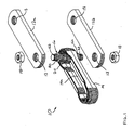
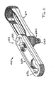
- a chain or section of chain 10 for conveying product along a conveying system includes a pair of side links 12a, 12b and a center link 14 ( FIGS. 1-3 ).
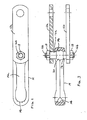
- the center link 14 is retained between the side links 12a, 12b by a double ended stud or stud type pin 16, which extends through a center region 14a of center link 14 and through an opening 13 in each side link 12a, 12b and is retained therein by a corresponding fastener or nut 18.
- Stud 16 includes a generally spherical or toroidal-shaped ball member 20 positioned generally at a mid-point or mid-region of a shaft portion 16a of stud 16.
- Chain 10 includes multiple linkages connected together in a continuous loop about a conveying system, as is known in the art. For ease of description, only one section or set of linkages of the chain is shown and described herein, with the other linkages of the chain being substantially identical.
- Stud 16 includes center or shaft portion 16a and a pair of opposite threaded portions or fastener portions or ends 16b. Threaded portions 16b are of a narrower diameter than shaft portion 16a, such that the ends of center portion 16a provide an abutting surface 16c against the fastener 18 as the fastener is tightened onto stud 16 or for abutting against an inward side of the respective side link 12a, 12b, to maintain the spacing between the side links when the chain is assembled. Stud 16 may comprise a metallic material, such as steel, stainless steel or iron or the like, similar to conventional studs or pins of chain for material handling systems and the like.
- Ball member 20 may be integrally formed as part of stud 16 or may be press-fit or otherwise secured on shaft portion 16a to retain the position of ball member 20 in the middle region of stud 16. However, ball member 20 may otherwise be loosely fit onto shaft portion 16a of stud 16 and allowed to slide along or rotate around stud 16, without affecting the scope of the present invention. Ball member 20 may comprise a metallic material or a plastic or polymeric material.
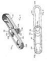
- Center link 14 is a generally oval shaped or elongated ring and includes an inner rounded or concave mating or engaging surface 14b ( FIGS. 2 and 3 ) at each end thereof for engaging and partially receiving ball member 20 therein to retain center link 14 at ball member 20 as the chain is moved along the conveying path.
- Ball member 20 thus allows for pivotal movement of center link 14 via sliding engagement of concave surface 14b along ball member 20.
- This provides greater flexibility to bolted chain 10 and may allow bolted chain 10 to negotiate sharper vertical curves in the conveying path without binding the links or joints of the chain.
- the ball member and correspondingly formed concave surface thus may distribute the loads over a generally constant surface area, reducing or substantially eliminating the stress concentration that typically occur when conventional chains articulate through vertical inclines and declines.
- the ball member and concave surface engagement may also function to distribute the loads between the chain links and stud or pin over a greater surface area than conventional chains. This decreases the wear on the bolt and chain links and may result in less maintenance and a greater life cycle for the chain.
- pin 16 is made to be selectively adjustable between at least three positions relative to the chain links in order to adjust the wear surface of the shaft portion relative to the chain links.
- the pin is generally non-rotatable relative to the chain links when in each of the at least three positions.
- the head portion of a pin of a section of chain may be non- circular shaped and the recessed portion of at least one of the side links may be correspondingly non-circular shaped, such that the head portion, and thus the pin, may be non-rotatably secured relative to the side link.
- the head portion and a recessed region of a side link may be formed with two or more sides to provide for non-rotational engagement between the head and the recessed region, while allowing the head and bolt or pin to be manually rotated to adjust or change the wear surface engagement of the shaft and ball member with the center link.
- the pin or bolt portion (shaft and head) of a bolted pin may be ratcheted or rotated sixty degrees or ninety degrees or some other amount (depending on the number of sides of the head and the recessed region) to provide a new wear surface of the shaft and ball member (the portion that engages the center link and wears as the links bend and turn relative to one another).
- the adjustable or dialable pin design of the present invention thus may provide for a significant increase in the life cycle of the pin, because the ball member (or spacer-ball-spacer assembly) may be replaced as needed, and/or the pin may be selectably rotated to provide a new wear surface as needed, which may substantially extend the overall life of the pin or bolted pin.
- Each wear surface may span or cover approximately sixty or ninety or one hundred twenty degrees or the like about the pin, whereby the pin may be rotated that amount as necessary to provide six or four or three different wear surfaces or wear surface portions about the pin and, thus, to facilitate control of the amount of wear or amount of time of wear on each wear surface portion.
- This may be especially useful in applications where the chain is an exact pitch design (the chain length is specified with a small tolerance range), and excessive wear in one or more of the pins may affect the pitch, which may cause the chain to bind or chains to bind (if two such chains are running alongside one another with something connected or cradled between them) or may otherwise adversely affect the chain or conveyor.
- each pin of such a chain may then be dialed or rotated to provide a new wear surface for each pin, thereby effectively resetting the pins to their original tolerances and thus resetting the chain to its initial specified length.
- each pin may be dialed to a second position or a third position or any other position to move a fresh wear surface to the wear position.
- only a first pin or set of pins may need to be reset to provide an appropriate adjustment.
- the degree of wear on the pin or shaft portion (or wear surface) may be monitored or determined, and the pin may be selectably rotated to limit wear on the wear surface of the pin. It is further envisioned that each station or lobe on the head portion of the pin may be marked or numbered to indicate which portion or portions of the wear surface have already been selected or used.
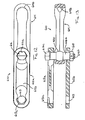
- a head portion 516c of a pin 516 and openings 513b of side links 512 may be non-circular, such that pin 516 is non-rotatably positioned at and through side links 512 of a chain or section of chain 510.
- the head portion 516c may be lobed or non-circular shaped with three or more sides or portions 516e (such as the three curved and generally equal-sized sides shown in FIGS.4 and 5 ), with the recessed area 513c correspondingly shaped to receive the head portion, such that the mating surfaces of the head portion 516c within the correspondingly formed recessed area or impression 513c in the side link 512 substantially precludes rotation of the pin 516 relative to the side links 512.
- one or more of the side portions of the head portion may engage a corresponding one or more of the sidewalls of the side link at the aperture to substantially preclude rotation of the pin relative to the side links.
- the wear surface of the shaft portion 516a and/or ball member 520 thus may be generally fixed relative to the side links 512 by substantially fixing head 516c within recess 513c, such that only a portion of the shaft and/or ball member will contact and wear against the concave surface 514b of the center link 514 as the chain travels along its conveying path.
- the pin may be generally non-rotatable relative to the chain links when in each of the positions (such as in each of the three positions in the illustrated embodiment of FIGS. 4 and 5 , or such as in each of the six positions in the illustrated embodiment of FIGS.6-8 , discussed below, or such as in any other number of positions suitable for such an arrangement), and may be selectably adjustable between the positions to adjust the wear surface of the shaft portion of the pin relative to the chain links, thereby providing selective engagement of a portion or portions of the wear surface with the chain links.
- Such an arrangement allows for controlling the wear and life cycle of the pin by wearing a particular wear surface of the pin at a time, and allows for controlled or manual or selective rotation from one wear surface of the pin to the next wear surface of the pin.
- the pin and side link arrangement of the present invention thus provides a dialable pin, which may be manually and selectably dialed or rotated to provide a new wear surface against the side link after the first wear surface has been sufficiently worn.
- a dialable pin which may be manually and selectably dialed or rotated to provide a new wear surface against the side link after the first wear surface has been sufficiently worn.
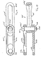
- a head portion 516c' of a pin 516' and openings 513b' of side links 512' may be non-circular, such that pin 516' sis non-rotatably positioned at and through side links 512' of a chain or section of chain 510'.
- the head portion 516c' may be generally hex-shaped, with the recessed area 513c' being correspondingly shaped to receive the head portion, such that the mating of the head portion 516c' within the correspondingly formed recessed area or impression 513c' in the side link 512' substantially precludes rotation of the pin 516' relative to the side links 512' in six positions.
- the wear surface of the shaft portion 516a' and/or ball member 520' may be generally fixed relative to the side links 512' by substantially fixing head 516c' within recess 513c', such that only a portion of the shaft and/or ball member will contact and wear against the concave surface 514b of the center link 514 as the chain travels along its conveying path.
- the wear surface may then be adjusted or dialed to a new surface by rotating the pin 516' to a next orientation relative to the recesses 513c' in the side links 512', as discussed above.
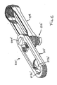
- a chain or section of chain 510" may include a pin 516", which may comprise shaped or lobed or hex-shaped head portions 516c" at opposite ends of a generally cylindrical shaft portion 516b".
- the center link 514" includes a generally flat or curved, non-concave surface 514b" for engaging the shaft portion 516b".
- Pin 516" and side links 512' may be otherwise substantially similar to pin 516' discussed above, such that a detailed discussion will not be repeated herein.
- a chain or section of chain 610 may include a threaded pin or bolt 616, which may comprise a shaft portion 616a and a shaped or lobed or hex-shaped head portion 616c at one end and a threaded portion 616b at an opposite end for receiving a nut or threaded fastener or the like 618 ( FIG. 13 ).
- Head portion 616c may be received in a correspondingly formed or shaped recess 613c in one side link 612a, while a generally cylindrical shaft portion 616a and/or threaded end portion 616b may extend through an opening 613 in the other side link 612b of chain 610.
- the center link 614 includes a concave inner surface 614b for engaging a ball member 620 positioned along shaft portion 616a of pin 616.
- Ball member 620 may be formed as part of shaft portion 616a or may be slid onto or formed or molded onto shaft portion 616a, and pin 616 may include a generally cylindrical sleeve portion over and along shaft portion 616a, such as any of the types of sleeves discussed above or below.
- Chain 610 may be otherwise substantially similar to chain 510, discussed above, such that a detailed discussion will not be repeated herein.
- a chain or section of chain 610' may include a threaded pin or bolt 616', which may comprise a shaft portion 616a' and a non-circular shaped or lobed or hex-shaped head portion 616c' at one end and a threaded portion 616b' at an opposite end for receiving a nut or threaded fastener or the like 618.
- Head portion 616c' may be received in a correspondingly formed or shaped recess 613c in one side link 612a, while a generally cylindrical shaft portion 616a' and/or threaded end portion 616b' may extend through an opening 613 in the other side link 612b of chain 610'.
- the center link 614' may include a generally flat or non-concave inner surface 614b' for engaging shaft portion 616a' of pin 616'.
- pin 616' may include a generally cylindrical sleeve portion over and along shaft portion 616a', such as the types of sleeve portions discussed above or below.
- Chain 610' may be otherwise substantially similar to chain 610, discussed above, such that a detailed discussion will not be repeated herein.
- the dialable pin configuration of the present invention thus may provide significantly greater life cycles for such chains and pins, since the pins do not have to be replaced when one or more of the pins wears a sufficient amount.
- Such a pin-head and side link design may be implemented with a pin with a ball member or the like or a pin with a generally cylindrical shaft portion and no ball member, without affecting the scope of the present invention.
- such a dialable pin concept is suitable for use on a double headed pin or a single headed or bolted pin, with the head or heads of the pin being lobed or non-circular shaped or formed and engaged with a correspondingly formed recess in one of the side links, while a threaded end of a bolted pin may extend through a circular opening in the other side link and may be secured therein by a nut or other fastener, without affecting the scope of the present invention.
- the ball members and/or the concave surfaces of the center links of the present invention may comprise a metallic material, or may comprise a nylon or plastic or polymeric material, without affecting the scope of the present invention.
- the selected material is preferably a highly durable material which may minimize wear of the ball and/or the concave surface when the chain is in use and moving through various curves while under load.
- the present invention provides a bolted or pinned or half-bolted chain which has improved flexibility to ease negotiation of the chain links through sharp vertical changes in the chain path.
- the ball members of the present invention allow for pivotable movement between the center link and side links as the chain negotiates through the conveying path. More particularly, the ball member allows the center link to pivot about a longitudinal axis of the bolt, stud or pin in a conventional manner, while also allowing the center link to pivot about the ball member in other directions as well, such as pivoting upward or downward relative to the side links.
- the ball member and bolt or stud combination of the present invention thus allows the bolted chain to negotiate inclines along the conveying path without binding or excessive wear occurring at the chain joints.
- the ball and socket type connection of the present invention allows the chain to flex about both axes, which further may allow the chain to twist or corkscrew over a sufficient length of track. Because the ball member may be loosely fit onto the bolt or stud, the ball member of the present invention provides for an easy assembly process of the bolt or stud and also facilitates easy disassembly or disconnection of the chain links for service or maintenance of the bolted chain. The present invention thus provides for a chain with much greater flexibility which is easy to manufacture and assemble.
Landscapes
- Engineering & Computer Science (AREA)
- General Engineering & Computer Science (AREA)
- Mechanical Engineering (AREA)
- Chain Conveyers (AREA)
- Devices For Conveying Motion By Means Of Endless Flexible Members (AREA)
- Escalators And Moving Walkways (AREA)
- Automatic Cycles, And Cycles In General (AREA)
Applications Claiming Priority (9)
| Application Number | Priority Date | Filing Date | Title |
|---|---|---|---|
| US36275102P | 2002-03-08 | 2002-03-08 | |
| US362751P | 2002-03-08 | ||
| US36739002P | 2002-03-25 | 2002-03-25 | |
| US367390P | 2002-03-25 | ||
| US38151802P | 2002-05-17 | 2002-05-17 | |
| US381518P | 2002-05-17 | ||
| US42557702P | 2002-11-12 | 2002-11-12 | |
| US425577P | 2002-11-12 | ||
| PCT/US2003/007248 WO2003076309A2 (en) | 2002-03-08 | 2003-03-07 | Conveyor chain |
Publications (3)
| Publication Number | Publication Date |
|---|---|
| EP1490278A2 EP1490278A2 (en) | 2004-12-29 |
| EP1490278A4 EP1490278A4 (en) | 2008-10-15 |
| EP1490278B1 true EP1490278B1 (en) | 2010-09-15 |
Family
ID=27808810
Family Applications (1)
| Application Number | Title | Priority Date | Filing Date |
|---|---|---|---|
| EP03716422A Expired - Lifetime EP1490278B1 (en) | 2002-03-08 | 2003-03-07 | Conveyor chain |
Country Status (9)
| Country | Link |
|---|---|
| US (1) | US6991094B2 (enExample) |
| EP (1) | EP1490278B1 (enExample) |
| JP (2) | JP2005519826A (enExample) |
| CN (1) | CN101683922B (enExample) |
| AT (1) | ATE481338T1 (enExample) |
| AU (1) | AU2003220129A1 (enExample) |
| CA (2) | CA2774912C (enExample) |
| DE (1) | DE60334196D1 (enExample) |
| WO (1) | WO2003076309A2 (enExample) |
Cited By (1)
| Publication number | Priority date | Publication date | Assignee | Title |
|---|---|---|---|---|
| US9482315B1 (en) | 2015-10-14 | 2016-11-01 | Columbia Steel Casting Co., Inc. | Stud end link |
Families Citing this family (46)
| Publication number | Priority date | Publication date | Assignee | Title |
|---|---|---|---|---|
| JP3555844B2 (ja) | 1999-04-09 | 2004-08-18 | 三宅 正二郎 | 摺動部材およびその製造方法 |
| US6666328B2 (en) * | 2001-08-07 | 2003-12-23 | Stapell/Guider Corporation | Long wear conveyor assembly |
| US7246699B2 (en) * | 2002-03-08 | 2007-07-24 | Frost Links, Inc. | Conveyor chain |
| JP2004138128A (ja) | 2002-10-16 | 2004-05-13 | Nissan Motor Co Ltd | 自動車エンジン用摺動部材 |
| US6969198B2 (en) | 2002-11-06 | 2005-11-29 | Nissan Motor Co., Ltd. | Low-friction sliding mechanism |
| JP3891433B2 (ja) | 2003-04-15 | 2007-03-14 | 日産自動車株式会社 | 燃料噴射弁 |
| EP1479946B1 (en) | 2003-05-23 | 2012-12-19 | Nissan Motor Co., Ltd. | Piston for internal combustion engine |
| EP1482190B1 (en) | 2003-05-27 | 2012-12-05 | Nissan Motor Company Limited | Rolling element |
| JP2004360649A (ja) | 2003-06-06 | 2004-12-24 | Nissan Motor Co Ltd | エンジン用ピストンピン |
| JP4863152B2 (ja) | 2003-07-31 | 2012-01-25 | 日産自動車株式会社 | 歯車 |
| CN101760286B (zh) | 2003-08-06 | 2013-03-20 | 日产自动车株式会社 | 低摩擦滑动机构、低摩擦剂组合物以及减小摩擦的方法 |
| JP2005054617A (ja) | 2003-08-08 | 2005-03-03 | Nissan Motor Co Ltd | 動弁機構 |
| JP4973971B2 (ja) | 2003-08-08 | 2012-07-11 | 日産自動車株式会社 | 摺動部材 |
| JP4117553B2 (ja) | 2003-08-13 | 2008-07-16 | 日産自動車株式会社 | チェーン駆動装置 |
| DE602004008547T2 (de) | 2003-08-13 | 2008-05-21 | Nissan Motor Co., Ltd., Yokohama | Struktur zur Verbindung von einem Kolben mit einer Kurbelwelle |
| US7771821B2 (en) | 2003-08-21 | 2010-08-10 | Nissan Motor Co., Ltd. | Low-friction sliding member and low-friction sliding mechanism using same |
| JP4539205B2 (ja) | 2003-08-21 | 2010-09-08 | 日産自動車株式会社 | 冷媒圧縮機 |
| EP1508611B1 (en) | 2003-08-22 | 2019-04-17 | Nissan Motor Co., Ltd. | Transmission comprising low-friction sliding members and transmission oil therefor |
| KR20070020194A (ko) * | 2003-11-10 | 2007-02-20 | 가부시키가이샤 제이텍트 | 동력 전달 체인과 동력 전달 장치 및 그 제조 방법 |
| ATE476382T1 (de) * | 2004-10-07 | 2010-08-15 | Pteris Global Ltd | Fördersystem |
| JP2009506962A (ja) * | 2005-09-02 | 2009-02-19 | スパン テック エルエルシー | モジュラーリンク式コンベヤベルトのための耐摩コネクタ |
| DE102005047205A1 (de) * | 2005-10-01 | 2007-04-12 | Demag Cranes & Components Gmbh | Vorrichtung zum Aufhängen einer Schiene, insbesondere einer Fahrschiene eines Hängeförderers oder eines Hebezeugs |
| EP1954602A2 (en) * | 2005-11-23 | 2008-08-13 | Frost Links, Inc. | Pin assembly for conveyor chain |
| US7325669B2 (en) * | 2005-11-23 | 2008-02-05 | Frost Links, Inc. | Measuring device for conveyor chain |
| US8657100B2 (en) | 2006-02-16 | 2014-02-25 | Frost Links, Inc. | Conveyor slide plate with reservoir |
| AU2007217940A1 (en) * | 2006-02-16 | 2007-08-30 | Frost Links, Inc. | Conveyor chain pin with reservoir |
| WO2007118058A2 (en) | 2006-04-03 | 2007-10-18 | Span Tech Llc | Powder coating product conveying components and related methods |
| CN101516746B (zh) * | 2006-08-24 | 2011-09-14 | 弗诺斯特链运有限公司 | 链条磨损监控装置 |
| US7762391B2 (en) * | 2008-07-10 | 2010-07-27 | Jager Todd G | Conveyor chain |
| US20110072944A1 (en) * | 2009-09-29 | 2011-03-31 | Jeffrey Eggers | Flexible linked cutting system |
| US8285494B2 (en) * | 2009-10-20 | 2012-10-09 | Tibor Vozner | Conveyor chain monitoring system and method |
| AU2010241266B2 (en) * | 2009-11-18 | 2015-03-12 | Muller Martini Holding Ag | Transport device for conveying printed products |
| CN102381542A (zh) * | 2011-11-23 | 2012-03-21 | 江苏华宇印涂设备集团有限公司 | 空罐烘房输送链 |
| CN102758879B (zh) * | 2012-07-26 | 2013-12-11 | 株洲职业技术学院 | 万向弯曲传动链条 |
| WO2014074594A1 (en) * | 2012-11-07 | 2014-05-15 | Frost Tech Llc | High load conveyor chain and method |
| WO2015138372A1 (en) * | 2014-03-10 | 2015-09-17 | Frost Tech Llc | Stainless and carbon steel conveyor chain and method |
| WO2016019193A2 (en) * | 2014-07-30 | 2016-02-04 | Itr America Llc | Cutting link for mining chain and mining pin retention system |
| CN105151650B (zh) * | 2015-09-15 | 2017-03-29 | 广州大学 | 一种板链式输送机 |
| WO2017077173A1 (en) * | 2015-11-06 | 2017-05-11 | Finnchain Oy | Formed piece for chain use |
| US10138685B1 (en) | 2015-12-18 | 2018-11-27 | Jeffrey Eggers | Drilling system with teeth driven in opposite directions |
| CA3031077A1 (en) * | 2016-07-18 | 2018-01-25 | Frost Tech Llc | Conveyor chain with adjustable link pins |
| CN106697759A (zh) * | 2017-03-07 | 2017-05-24 | 苏州环球集团科技股份有限公司 | 一种侧弯输送链 |
| US11846187B2 (en) | 2017-08-30 | 2023-12-19 | Itr America, Llc | Mining pin retention system |
| US11047245B2 (en) | 2019-08-12 | 2021-06-29 | Raytheon Technologies Corporation | CMC component attachment pin |
| CN111620048B (zh) * | 2020-06-03 | 2022-06-21 | 嘉善伟悦紧固件有限公司 | 一种紧固件生产用上料装置 |
| MA65760A1 (fr) * | 2021-12-09 | 2024-10-31 | Rexnord Industries, Llc | Systèmes et procédés pour l'assemblage et la réparation de chaînes |
Family Cites Families (23)
| Publication number | Priority date | Publication date | Assignee | Title |
|---|---|---|---|---|
| US1660354A (en) * | 1922-01-23 | 1928-02-28 | Phelps Paul | Chain belt |
| US2600174A (en) * | 1948-11-18 | 1952-06-10 | Sheehan James William | Conveyer chain |
| FR1431081A (fr) * | 1965-01-29 | 1966-03-11 | Sedis Transmissions Mec | Maillon de chaîne et chaîne en comportant application |
| US4114467A (en) * | 1976-12-02 | 1978-09-19 | Rexnord Inc. | Snap-on wear pad |
| JPS6093017A (ja) * | 1983-10-28 | 1985-05-24 | Hitachi Ltd | ねじれ走行可能なコンベヤチエン |
| DE3408295C1 (de) | 1984-03-07 | 1985-10-24 | Hartmut Dipl.-Ing. 4770 Soest Schrage | Kette aus nichtmetallischen Werkstoffen und Verfahren zu ihrer Herstellung |
| US5215616A (en) * | 1986-03-14 | 1993-06-01 | Envirex Inc. | Method for manufacturing a high strength, non-metallic transmission chain |
| US5121831A (en) * | 1990-01-08 | 1992-06-16 | Carondelet Foundry Company | Grate conveyor link and method of manufacture |
| US5305872A (en) * | 1992-01-30 | 1994-04-26 | Esco Corporation | Chain |
| US5378205A (en) | 1992-08-05 | 1995-01-03 | Gohl; Allen P. | Extruded metal chain pin |
| DE4300160B4 (de) * | 1993-01-07 | 2004-02-05 | Sucker-Müller-Hacoba GmbH & Co., i.Ins. | Spannrahmenkette |
| FI101098B (fi) * | 1996-05-03 | 1998-04-15 | Finnketju Invest Oy | Menetelmä ketjun käyttöön ja ketju |
| JPH107224A (ja) * | 1996-06-24 | 1998-01-13 | Toray Ind Inc | 曲線搬送用チェーン |
| JP3572821B2 (ja) * | 1996-08-05 | 2004-10-06 | 株式会社ダイフク | チェーン |
| JPH10250818A (ja) * | 1997-03-11 | 1998-09-22 | Tsubakimoto Chain Co | 焼結含油ブシュコンベヤチェーン |
| SE511512C2 (sv) * | 1997-09-19 | 1999-10-11 | Flexlink Systems Ab | Kedjelänk för transportör |
| JPH11286317A (ja) * | 1998-03-31 | 1999-10-19 | Tsubakimoto Chain Co | 増速アキュムレートコンベヤチェーン |
| US6138820A (en) * | 1998-05-15 | 2000-10-31 | Westar Mfg. Corp. | Conveyor chain link |
| CN2370216Y (zh) * | 1999-03-25 | 2000-03-22 | 张兴东 | 封闭式链条 |
| US6161685A (en) | 1999-03-26 | 2000-12-19 | Rexnord Corporation | Thermoplastic chain link for a modular conveyor chain |
| GB9907173D0 (en) | 1999-03-30 | 1999-05-26 | Renold Plc | A chain |
| EP1237804B1 (en) * | 1999-11-26 | 2004-03-03 | Gram Equipment A/S | A drained conveyor chain link |
| US6666328B2 (en) * | 2001-08-07 | 2003-12-23 | Stapell/Guider Corporation | Long wear conveyor assembly |
-
2003
- 2003-03-07 CA CA2774912A patent/CA2774912C/en not_active Expired - Lifetime
- 2003-03-07 JP JP2003574540A patent/JP2005519826A/ja active Pending
- 2003-03-07 EP EP03716422A patent/EP1490278B1/en not_active Expired - Lifetime
- 2003-03-07 AT AT03716422T patent/ATE481338T1/de not_active IP Right Cessation
- 2003-03-07 CN CN200910204662.XA patent/CN101683922B/zh not_active Expired - Fee Related
- 2003-03-07 WO PCT/US2003/007248 patent/WO2003076309A2/en not_active Ceased
- 2003-03-07 DE DE60334196T patent/DE60334196D1/de not_active Expired - Lifetime
- 2003-03-07 CA CA2477686A patent/CA2477686C/en not_active Expired - Fee Related
- 2003-03-07 AU AU2003220129A patent/AU2003220129A1/en not_active Abandoned
- 2003-03-07 US US10/383,825 patent/US6991094B2/en not_active Expired - Lifetime
-
2009
- 2009-05-20 JP JP2009122330A patent/JP5017316B2/ja not_active Expired - Fee Related
Cited By (1)
| Publication number | Priority date | Publication date | Assignee | Title |
|---|---|---|---|---|
| US9482315B1 (en) | 2015-10-14 | 2016-11-01 | Columbia Steel Casting Co., Inc. | Stud end link |
Also Published As
| Publication number | Publication date |
|---|---|
| AU2003220129A8 (en) | 2003-09-22 |
| US6991094B2 (en) | 2006-01-31 |
| EP1490278A2 (en) | 2004-12-29 |
| DE60334196D1 (de) | 2010-10-28 |
| CA2774912A1 (en) | 2003-09-18 |
| WO2003076309A2 (en) | 2003-09-18 |
| JP5017316B2 (ja) | 2012-09-05 |
| AU2003220129A1 (en) | 2003-09-22 |
| WO2003076309A3 (en) | 2003-11-13 |
| ATE481338T1 (de) | 2010-10-15 |
| CN101683922B (zh) | 2014-06-18 |
| CA2774912C (en) | 2016-05-17 |
| EP1490278A4 (en) | 2008-10-15 |
| CN101683922A (zh) | 2010-03-31 |
| CA2477686A1 (en) | 2003-09-18 |
| JP2009215081A (ja) | 2009-09-24 |
| JP2005519826A (ja) | 2005-07-07 |
| CA2477686C (en) | 2012-05-29 |
| US20030168323A1 (en) | 2003-09-11 |
Similar Documents
| Publication | Publication Date | Title |
|---|---|---|
| EP1490278B1 (en) | Conveyor chain | |
| US7726469B2 (en) | Conveyor chain | |
| CA2237686C (en) | Side-flexing conveyor construction | |
| US3231069A (en) | Chain link | |
| US20130284569A1 (en) | Conveying device | |
| US4911682A (en) | Cambered pin CVT chain belt | |
| US8079463B2 (en) | Conveying device, rolling body and conveying body | |
| EP1142806A1 (en) | Roller for chain and chain equipped with the roller | |
| US3363745A (en) | Pivotal connection for links of flat top conveyor | |
| US4227425A (en) | Single rocker joint drive chain | |
| CA1104514A (en) | Chain pin assembly with captive securing means | |
| JPH06503156A (ja) | 単一ピンロッカジョイントcvtチェーン | |
| US3107777A (en) | Conveyor chain | |
| US6244032B1 (en) | Chain | |
| US7600633B2 (en) | Pin assembly for conveyor chain | |
| JP3637562B2 (ja) | 搬送用チェーンの連結構造 | |
| US4020629A (en) | Solid side bar rivetless chain | |
| CA2600729C (en) | Conveying device, rolling body and conveying body | |
| US4186831A (en) | Connector for catenary conveyor belt idler rolls | |
| US7150142B2 (en) | Chicken chain | |
| US3826150A (en) | Link configuration for distribution of transverse loads on drive and drag chain | |
| LV13935B (lv) | Izjaucama plāksnīšu ķēde ar ritberzes šarnīriem |
Legal Events
| Date | Code | Title | Description |
|---|---|---|---|
| PUAI | Public reference made under article 153(3) epc to a published international application that has entered the european phase |
Free format text: ORIGINAL CODE: 0009012 |
|
| 17P | Request for examination filed |
Effective date: 20041008 |
|
| AK | Designated contracting states |
Kind code of ref document: A2 Designated state(s): AT BE BG CH CY CZ DE DK EE ES FI FR GB GR HU IE IT LI LU MC NL PT RO SE SI SK TR |
|
| AX | Request for extension of the european patent |
Extension state: AL LT LV MK |
|
| A4 | Supplementary search report drawn up and despatched |
Effective date: 20080917 |
|
| 17Q | First examination report despatched |
Effective date: 20090331 |
|
| GRAP | Despatch of communication of intention to grant a patent |
Free format text: ORIGINAL CODE: EPIDOSNIGR1 |
|
| GRAS | Grant fee paid |
Free format text: ORIGINAL CODE: EPIDOSNIGR3 |
|
| GRAA | (expected) grant |
Free format text: ORIGINAL CODE: 0009210 |
|
| AK | Designated contracting states |
Kind code of ref document: B1 Designated state(s): AT BE BG CH CY CZ DE DK EE ES FI FR GB GR HU IE IT LI LU MC NL PT RO SE SI SK TR |
|
| REG | Reference to a national code |
Ref country code: CH Ref legal event code: EP Ref country code: GB Ref legal event code: FG4D |
|
| REG | Reference to a national code |
Ref country code: IE Ref legal event code: FG4D |
|
| REF | Corresponds to: |
Ref document number: 60334196 Country of ref document: DE Date of ref document: 20101028 Kind code of ref document: P |
|
| REG | Reference to a national code |
Ref country code: NL Ref legal event code: VDEP Effective date: 20100915 |
|
| PG25 | Lapsed in a contracting state [announced via postgrant information from national office to epo] |
Ref country code: FI Free format text: LAPSE BECAUSE OF FAILURE TO SUBMIT A TRANSLATION OF THE DESCRIPTION OR TO PAY THE FEE WITHIN THE PRESCRIBED TIME-LIMIT Effective date: 20100915 Ref country code: AT Free format text: LAPSE BECAUSE OF FAILURE TO SUBMIT A TRANSLATION OF THE DESCRIPTION OR TO PAY THE FEE WITHIN THE PRESCRIBED TIME-LIMIT Effective date: 20100915 |
|
| PG25 | Lapsed in a contracting state [announced via postgrant information from national office to epo] |
Ref country code: CY Free format text: LAPSE BECAUSE OF FAILURE TO SUBMIT A TRANSLATION OF THE DESCRIPTION OR TO PAY THE FEE WITHIN THE PRESCRIBED TIME-LIMIT Effective date: 20100915 Ref country code: SI Free format text: LAPSE BECAUSE OF FAILURE TO SUBMIT A TRANSLATION OF THE DESCRIPTION OR TO PAY THE FEE WITHIN THE PRESCRIBED TIME-LIMIT Effective date: 20100915 |
|
| PG25 | Lapsed in a contracting state [announced via postgrant information from national office to epo] |
Ref country code: SE Free format text: LAPSE BECAUSE OF FAILURE TO SUBMIT A TRANSLATION OF THE DESCRIPTION OR TO PAY THE FEE WITHIN THE PRESCRIBED TIME-LIMIT Effective date: 20100915 Ref country code: GR Free format text: LAPSE BECAUSE OF FAILURE TO SUBMIT A TRANSLATION OF THE DESCRIPTION OR TO PAY THE FEE WITHIN THE PRESCRIBED TIME-LIMIT Effective date: 20101216 |
|
| PG25 | Lapsed in a contracting state [announced via postgrant information from national office to epo] |
Ref country code: SK Free format text: LAPSE BECAUSE OF FAILURE TO SUBMIT A TRANSLATION OF THE DESCRIPTION OR TO PAY THE FEE WITHIN THE PRESCRIBED TIME-LIMIT Effective date: 20100915 Ref country code: RO Free format text: LAPSE BECAUSE OF FAILURE TO SUBMIT A TRANSLATION OF THE DESCRIPTION OR TO PAY THE FEE WITHIN THE PRESCRIBED TIME-LIMIT Effective date: 20100915 Ref country code: IT Free format text: LAPSE BECAUSE OF FAILURE TO SUBMIT A TRANSLATION OF THE DESCRIPTION OR TO PAY THE FEE WITHIN THE PRESCRIBED TIME-LIMIT Effective date: 20100915 Ref country code: CZ Free format text: LAPSE BECAUSE OF FAILURE TO SUBMIT A TRANSLATION OF THE DESCRIPTION OR TO PAY THE FEE WITHIN THE PRESCRIBED TIME-LIMIT Effective date: 20100915 Ref country code: PT Free format text: LAPSE BECAUSE OF FAILURE TO SUBMIT A TRANSLATION OF THE DESCRIPTION OR TO PAY THE FEE WITHIN THE PRESCRIBED TIME-LIMIT Effective date: 20110117 Ref country code: NL Free format text: LAPSE BECAUSE OF FAILURE TO SUBMIT A TRANSLATION OF THE DESCRIPTION OR TO PAY THE FEE WITHIN THE PRESCRIBED TIME-LIMIT Effective date: 20100915 Ref country code: EE Free format text: LAPSE BECAUSE OF FAILURE TO SUBMIT A TRANSLATION OF THE DESCRIPTION OR TO PAY THE FEE WITHIN THE PRESCRIBED TIME-LIMIT Effective date: 20100915 |
|
| PG25 | Lapsed in a contracting state [announced via postgrant information from national office to epo] |
Ref country code: ES Free format text: LAPSE BECAUSE OF FAILURE TO SUBMIT A TRANSLATION OF THE DESCRIPTION OR TO PAY THE FEE WITHIN THE PRESCRIBED TIME-LIMIT Effective date: 20101226 Ref country code: BE Free format text: LAPSE BECAUSE OF FAILURE TO SUBMIT A TRANSLATION OF THE DESCRIPTION OR TO PAY THE FEE WITHIN THE PRESCRIBED TIME-LIMIT Effective date: 20100915 |
|
| PLBE | No opposition filed within time limit |
Free format text: ORIGINAL CODE: 0009261 |
|
| STAA | Information on the status of an ep patent application or granted ep patent |
Free format text: STATUS: NO OPPOSITION FILED WITHIN TIME LIMIT |
|
| 26N | No opposition filed |
Effective date: 20110616 |
|
| PG25 | Lapsed in a contracting state [announced via postgrant information from national office to epo] |
Ref country code: DK Free format text: LAPSE BECAUSE OF FAILURE TO SUBMIT A TRANSLATION OF THE DESCRIPTION OR TO PAY THE FEE WITHIN THE PRESCRIBED TIME-LIMIT Effective date: 20100915 |
|
| REG | Reference to a national code |
Ref country code: DE Ref legal event code: R097 Ref document number: 60334196 Country of ref document: DE Effective date: 20110616 |
|
| PG25 | Lapsed in a contracting state [announced via postgrant information from national office to epo] |
Ref country code: MC Free format text: LAPSE BECAUSE OF NON-PAYMENT OF DUE FEES Effective date: 20110331 |
|
| REG | Reference to a national code |
Ref country code: CH Ref legal event code: PL |
|
| REG | Reference to a national code |
Ref country code: IE Ref legal event code: MM4A |
|
| PG25 | Lapsed in a contracting state [announced via postgrant information from national office to epo] |
Ref country code: CH Free format text: LAPSE BECAUSE OF NON-PAYMENT OF DUE FEES Effective date: 20110331 Ref country code: LI Free format text: LAPSE BECAUSE OF NON-PAYMENT OF DUE FEES Effective date: 20110331 Ref country code: IE Free format text: LAPSE BECAUSE OF NON-PAYMENT OF DUE FEES Effective date: 20110307 |
|
| PG25 | Lapsed in a contracting state [announced via postgrant information from national office to epo] |
Ref country code: LU Free format text: LAPSE BECAUSE OF NON-PAYMENT OF DUE FEES Effective date: 20110307 |
|
| PG25 | Lapsed in a contracting state [announced via postgrant information from national office to epo] |
Ref country code: TR Free format text: LAPSE BECAUSE OF FAILURE TO SUBMIT A TRANSLATION OF THE DESCRIPTION OR TO PAY THE FEE WITHIN THE PRESCRIBED TIME-LIMIT Effective date: 20100915 Ref country code: BG Free format text: LAPSE BECAUSE OF FAILURE TO SUBMIT A TRANSLATION OF THE DESCRIPTION OR TO PAY THE FEE WITHIN THE PRESCRIBED TIME-LIMIT Effective date: 20101215 |
|
| PG25 | Lapsed in a contracting state [announced via postgrant information from national office to epo] |
Ref country code: HU Free format text: LAPSE BECAUSE OF FAILURE TO SUBMIT A TRANSLATION OF THE DESCRIPTION OR TO PAY THE FEE WITHIN THE PRESCRIBED TIME-LIMIT Effective date: 20100915 |
|
| REG | Reference to a national code |
Ref country code: FR Ref legal event code: PLFP Year of fee payment: 13 |
|
| REG | Reference to a national code |
Ref country code: FR Ref legal event code: PLFP Year of fee payment: 14 |
|
| REG | Reference to a national code |
Ref country code: FR Ref legal event code: PLFP Year of fee payment: 15 |
|
| REG | Reference to a national code |
Ref country code: FR Ref legal event code: PLFP Year of fee payment: 16 |
|
| PGFP | Annual fee paid to national office [announced via postgrant information from national office to epo] |
Ref country code: DE Payment date: 20200324 Year of fee payment: 18 Ref country code: GB Payment date: 20200211 Year of fee payment: 18 |
|
| PGFP | Annual fee paid to national office [announced via postgrant information from national office to epo] |
Ref country code: FR Payment date: 20200324 Year of fee payment: 18 |
|
| REG | Reference to a national code |
Ref country code: DE Ref legal event code: R119 Ref document number: 60334196 Country of ref document: DE |
|
| GBPC | Gb: european patent ceased through non-payment of renewal fee |
Effective date: 20210307 |
|
| PG25 | Lapsed in a contracting state [announced via postgrant information from national office to epo] |
Ref country code: DE Free format text: LAPSE BECAUSE OF NON-PAYMENT OF DUE FEES Effective date: 20211001 Ref country code: FR Free format text: LAPSE BECAUSE OF NON-PAYMENT OF DUE FEES Effective date: 20210331 Ref country code: GB Free format text: LAPSE BECAUSE OF NON-PAYMENT OF DUE FEES Effective date: 20210307 |