EP1237804B1 - A drained conveyor chain link - Google Patents
A drained conveyor chain link Download PDFInfo
- Publication number
- EP1237804B1 EP1237804B1 EP00979452A EP00979452A EP1237804B1 EP 1237804 B1 EP1237804 B1 EP 1237804B1 EP 00979452 A EP00979452 A EP 00979452A EP 00979452 A EP00979452 A EP 00979452A EP 1237804 B1 EP1237804 B1 EP 1237804B1
- Authority
- EP
- European Patent Office
- Prior art keywords
- chain
- bushing
- insert
- chain link
- contact hole
- Prior art date
- Legal status (The legal status is an assumption and is not a legal conclusion. Google has not performed a legal analysis and makes no representation as to the accuracy of the status listed.)
- Expired - Lifetime
Links
Images


Classifications
-
- B—PERFORMING OPERATIONS; TRANSPORTING
- B65—CONVEYING; PACKING; STORING; HANDLING THIN OR FILAMENTARY MATERIAL
- B65G—TRANSPORT OR STORAGE DEVICES, e.g. CONVEYORS FOR LOADING OR TIPPING, SHOP CONVEYOR SYSTEMS OR PNEUMATIC TUBE CONVEYORS
- B65G17/00—Conveyors having an endless traction element, e.g. a chain, transmitting movement to a continuous or substantially-continuous load-carrying surface or to a series of individual load-carriers; Endless-chain conveyors in which the chains form the load-carrying surface
- B65G17/30—Details; Auxiliary devices
- B65G17/38—Chains or like traction elements; Connections between traction elements and load-carriers
-
- B—PERFORMING OPERATIONS; TRANSPORTING
- B65—CONVEYING; PACKING; STORING; HANDLING THIN OR FILAMENTARY MATERIAL
- B65G—TRANSPORT OR STORAGE DEVICES, e.g. CONVEYORS FOR LOADING OR TIPPING, SHOP CONVEYOR SYSTEMS OR PNEUMATIC TUBE CONVEYORS
- B65G2201/00—Indexing codes relating to handling devices, e.g. conveyors, characterised by the type of product or load being conveyed or handled
- B65G2201/02—Articles
Definitions
- the present invention concerns a chain link with bushing in a drive chain.
- the invention also concerns the use of such a chain link.
- chain systems In connection with conveyor chains by the manufacturing of goods, chain systems are used for conveying holders/containers/trays on/in which the goods are placed during the different production steps.
- These chains may be designed in different ways, for sprocket wheels as well as for toothed chains.
- One of the embodiments, which is widely used, is a roller chain where the chain has great resemblance to chains used for bicycles, motorcycles, etc.
- the chain pins are fastened, usually riveted, to the outer fishplates while the bushing through which the chain pin is disposed is connected with the inner fishplates.
- a lubricant is often used in the bushings. If a chain for conveyor belts is used for foodstuff production, it is, however, inappropriate that the chain is lubricated with a lubricant as this lubricant, by mixing with dust and the like, under unfavourable circumstances may fall off the chain and contaminate the foodstuff during the process. By foodstuff production, on the other side, if the chain is not lubricated, water may be collected in the assembly bushings of the chain. By the making of freezer goods, like icecream products, where the conveyor runs through a freezer tunnel, the consequence is, in that case, that the chain becomes stiff or that the chain breaks which is a well-known problem and a great drawback.
- the object of the invention is to indicate a chain link with bushing for drive chains, preferably conveyor chains, where no water is collected in the bushing of the chain links even if no water repelling lubricants are used.
- the bushings according to the invention are provided with drain holes wherethrough possible collected water may run out of the bushing.
- These drain holes may be provided at different places in the bushing, depending of the form of chain and the orientation of conveying of the chain, for example the holes may be provided in the centre or along the rim of the bushing, at the upper side or the lower side of the chain link, or in direction parallel with the direction of advancing the chain. In principle there is no limit to the position and the number of holes in the bushing.
- Conveyor chains are often used with the links oriented so that the chain pins are mainly vertical. In such a case it is advantageous to have the holes provided in the lower part of the bushing. In order that the chain may be turned also, the bushings may advantageously be provided with drain holes both in the upper and the lower part of the bushing.
- chain links according to the invention with bushing provided with drain hole are particularly applicable to conveyor chains. Since conveyor chains are to be laterally flexible, the hole of the bushing in which the chain pin is disposed is usually made somewhat larger than the chain pin itself. The increased volume between the chain pin and the inner wall of the bushing causes a reduction of the capillary forces so that water more easily runs out of this volume.
- the contact surface between the chain pin the bushing hole is very small, especially if the contact surface does not extend along the whole bushing hole but only along a part - the contact part - of the hole. This is unfavourable as hereby large surface pressures occurs.
- the contact part, at its front part is formed with a bending radius corresponding to the radius of the chain pin. In this way the contact surface is relatively great by advancing the chain straightly as the chain pin bears against the face of the contact surface with a relative large part of the surface.
- the part of the bushing hole extending through the contact part will be designated contact hole in the following. It is noted that the contact hole may be shorter than the bushing hole itself.
- this contact hole has a cross-section being elongate, for example oval, whereby the chain is laterally flexible.
- the elongate contact hole By forming the elongate contact hole with a width increasing with the distance from the front edge of the hole, a further advantageous function is achieved. In case that all the water is not running out of the bushing, for example if a little water is retained around the chain pin due to capillary forces, by ice formation on the contact surface between the chain pin and the bushing there will be enough space for the chain pin in case of its backwards sliding, whereby breakage of the chain is avoided.
- the shape of the hole thus performs a number of different functions in combination.
- a bushing consisting partly of a tubular bushing part with an inner duct and partly of one or two bushing inserts which are disposed in this duct.
- the tubular bushing part may be designed as a traditional cylindric bushing known from common roller chains like bicycle chains.
- the bushing inserts disposed in the inner duct of the bushing are provided with a through-going hole through which the chain pin is provided.
- the inserts comprise the contact part, i.e. the chain pin is in contact with the bushing inserts and not directly with the inner duct of the bushing when advancing the drive chain.
- the previously mentioned bushing hole is thereby constituted by the hole through the insert and the remaining part of the inner duct which is not covered by the insert.
- a first advantage is that the tubular bushing part of the invention may be constituted by the cylindric bushing of steel known from traditional roller chains.
- the insert then comprises the contact part the hole of which - the contact hole - for the chain pin may be shaped elongate in cross-section so that the contact hole has the advantageous properties described hereinabove.
- the making of the chain with chain links according to the invention is relatively simple as only few modifications of existing production steps are required for roller or bushing chains.
- the tubular bushing part of the bushing may be cylindric or with other cross-section, for example quadratic.
- a quadratic cross-section has the advantage that the insert in the bushing will be prevented from rotating in the bushing, thus ensuring that the contact hole of the insert maintains its orientation, also under load and by long-time operation.
- the inserts may be made of a material, for example a polymer having small sliding resistance. Furthermore, the inserts may be made of a material being water lubricating. In this way, wear due to lack of lubrication from conventional lubricants is reduced.
- a third advantage is that exactly the inserts constitute the primary wear parts on the chain.
- the chain can be disassembled by pressing the chain pins out of the chain links, and new inserts may be provided, whereby the chain may be re-used after assembly.
- the inserts thus have a cost-saving function with environment-friendly aspects.
- a fourth advantage is that the inserts are a relatively small part of the chain which easily may be modified if another shape of the contact hole with the contact surface for the chain pin is desired.
- the chain link according to the invention is provided with inserts having a collar extending from the inner duct to and around the edge of the inner fishplate and extending in the interspace between the outer fishplate and the inner fishplate.
- This collar prevents that the insert rotates in the inner duct in the tubular bushing if this duct is cylindrical.
- the collar reduces the friction between the inner and the outer fishplates if the collar is made of a friction reducing and/or water lubricating material.
- a drain hole in the bushing is advantageously provided in the insert.
- the collar ensures the existence of a certain distance between the inner and the outer fishplates where the water may run out of the bushing through a hole in the insert.
- the chain pin is enclosed by a closely fitting insert.
- the bushing hole which below is designated the contact hole
- This contact hole may thus have an elongate cross-section, e.g. oval, whereas the insert enclosing the chain pin has an outer circular cross-section.
- the front part of the contact hole is designed with an contour, e.g. bending radius, corresponding to the front contour of the insert whereby is ensured a large surface of contact between the insert and the contact hole when running.
- the elongate cross-section provides for a reduction of capillary forces in the hole and lateral flexibility of the chain.
- the bushing hole is circular whereas the insert enclosing the chain pin, advantageously of polymer, is elongate.
- the front contact surface of the insert has bending radius corresponding to bending radius of the front part of the contact hole in order to ensure a large surface of contact.
- the cross-section of the insert is shorter than the bushing hole whereby is achieved the same advantages as described above.
- chain link according to the invention is illustrated as chain link for a roller chain even though the invention may also be used in other types of chains, cf. the above description.
- Figure 1 shows different types of chains where bushings typically are or may be used.
- Figure 1a shows a roller chain with rolls around the bushing
- Figure 1b shows a bushing chain similar to the roller chain but without the rolls around the bushing
- Figure 1c shows a toothed chain where toothed chains, however, can assume many different forms
- Figure 1d shows a so-called Gall chain
- Figure 1e shows a so-called Fleyer chain
- Figure 1f a Rotary chain.
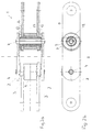
- FIG 2 shows a chain link according to the invention in the shape of a link 1 for a roller chain.
- the chain is shown in Figure 2a as seen from the side and in Figure 2b as seen from below. It is noted that the chain shown is intended for use in a chain conveyor and in such a way that the chain pins are oriented vertically.
- the chain has a number of similarities with a traditional roller chain and comprises outer fishplates 2 and inner fishplates 3, where the two outer fishplates 2 are rotatably connected with the inner fishplates 3 via a chain pin 4 which is fastened to the outer fishplates 3.
- a roller 5 around the bushing reduces wear on the bushing during operation.
- the fishplates 2 and the rollers 5 in the chain link according to the invention can be made from different materials. For application in the food industry, the materials are advantageously stainless steel and/or polymer materials.
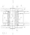
- FIG 3 shows a part of the picture of the chain link of Figure 2 in an enlarged version.
- the chain link differs from known art by the form of the bushing which comprises a tubular bushing part 6 and a two-piece insert 7.
- the insert may also be designed as a single insert or as two parts that do not extend completely to the middle of the bushing part 6.
- the insert comprises a collar 8 extending from the inner duct 9 to and around the edge 11 of the inner fishplates 3 and extending in the interspace 10 between the outer fishplates 2 and the inner fishplates 3.
- the insert 7 is provided with drain holes 12 (see also Figure 2b) which are disposed in an interspace 13 between the inner fishplates 3 and the outer fishplates 2.
- the inner duct 9 is constituted by an interspace formed between the inner side of the tubular bushing part 6 of the bushing and the chain pin 4.
- the insert 7 passes through and fills up the whole inner duct 9 of the tubular bushing part 6.
- a contact hole 17 with contact surface 14 thus extends through the whole inner duct 9 whereby a contact part 15 extends through the whole insert 7.
- the contact part 15 is a part of the insert 7 being in contact with the contact surface 14.
- the insert 7 may, however, be limited to only extending partly into the tubular bushing part 6. whereby the contact part 15 and the contact surface 14 become lesser.
- the tubular bushing part 6 is preferably cylindric but other shapes may be used with advantage, e.g. angular, such as quadratic.
- angular such as quadratic.
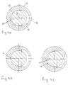
- Figure 4 shows the cross-section of the contact part 15 of the insert which the chain pin 4 is in contact with.
- the outer contour 16 of the contact part 15 largely illustrates the inner duct 9 of the bushing.
- the contact hole 17 in the insert 7, where the contact hole 17 constitutes a part of the bushing hole, is elongate and in connection with a drain hole 12 which is directed rearwards in relation to the drive direction of the chain.
- the contact surface 14 will be relatively large by straight running of the chain.
- the elongate hole is shaped so that its width increases with the distance from the front edge 18 of the hole 17.
- FIG. 5 shows a chain link 1' in an alternative embodiment.
- the chain link shows a chain link according to the invention in the shape of a link 1 for a roller chain.
- the chain is shown in Figure 5a as seen from the side and in cross-section, and in Figure 5b as seen from below and in cross-section. It is noted that also the chain shown is intended for use in a chain conveyor, and so that the chain pins 4 are oriented vertically.
- the chain has a number of similarities with a traditional roller chain and comprises outer fishplates 2 and inner fishplates 3 where the two outer fishplates 2 are rotatably connected with the inner fishplates 3 via a chain pin 4' which is fastened to the outer fishplates 2.
- a roller 5 around the bushing reduces wear on the bushing during operation.
- the fishplates 2 and the rollers 5 in the chain link according to the invention may be made of different materials, such as polymer or metal.
- FIG 6 shows a partial view of the chain link of Figure 5 in an enlarged version.
- the chain link differs from known art by an insert 7' between the chain pin 4' and the bushing part 6' where the insert 7' is rotationally fixed to the chain pin 4'.
- Drain holes may be made in this embodiment as drain holes 12' in the bushing part 6' itself , which in principle is analogous to the embodiment as shown on Figure 3, or as interspaces 12" between the end edge 20 of the bushing part 6' and the adjoining fishplate 2.
- Figure 7a shows the insert 7' in cross-section
- Figure 7b shows the insert 7' as seen from the end.
- the hole 22 through the insert corresponds to the cross-section of the chain pin 4' and is designed so that a rotationally fixed connection between the chain pin 4' and the insert 7' is ensured.
- Figure 7c is shown a cross-section of the chain pin 4' and the enclosing insert 7' in the contact hole 17'.
- the contact hole 17' in the bushing part 6' is circular in this case.
- the cross-section of the insert 7' is not circular but has an elongate shape so that the cross-section of the insert (7') in longitudinal direction A is less than the cross-section of the insert in the transverse direction B.
- the contact hole 17' does not necessarily have a circular cross-section but has, however, constant bending radius in the front part 21 of the contact hole where the insert 7' with the same bending radius of the front part of the insert 7' is in contact with the contact hole.
- the insert 7' extends through the contact hole 17' from one fishplate 2 to the other fishplate 2. However, it is also possible that the insert 7' only partly extends through the contact hole 17. Hereby the contact part 15', which is the part of the insert being in contact with the contact surface 14', becomes shorter. In this case the above described shaping of the insert 7' only concerns the contact part 15' of the insert.
Landscapes
- Engineering & Computer Science (AREA)
- Mechanical Engineering (AREA)
- Chain Conveyers (AREA)
- Intermediate Stations On Conveyors (AREA)
- Escalators And Moving Walkways (AREA)
Abstract
Description
Claims (13)
- A chain link with bushing in a drive chain, characterised in that the bushing comprises at least one drain hole (12,12',12") for draining liquid inappropriately collected in the bushing.
- A chain link according to claim 1, characterised in that the chain link comprises a chain pin (4) extending through the bushing, that the bushing comprises a contact part (15) with contact hole (17), that the chain pin (4) is in contact with the contact part (15) when advancing the drive chain, that radius of the front part of the chain pin (4) corresponds to bending radius in the front part of the contact hole (17), that the contact hole (17) has a cross-section which is elongate so that the cross-section is greater in the longitudinal direction of the chain than perpendicularly thereto.
- A chain link according to claim 2, characterised in that the width of the contact hole (17) increases with the distance from the from edge (18) of the contact hole (17).
- A chain link according to claim 1 - 3, characterised in that the chain link, suitable for forming a part of a drive chain in the shape of a bushing chain or roller chain, comprises two outer fishplates (2) connected by means of chain pins (4), and two inner fish plates (3) connected by means of two bushings, that each of the bushings comprises an inner duct (9) and at least one bushing insert (7) with contact hole (17), the bushing insert (7) being disposed at least partly in the inner duct (9).
- A chain link according to claim 4, characterised in that the bushing insert comprises a collar (8) extending from the inner duct (9) to and around the edge (11) of the inner fishplate (3) and extending in the interspace (10) between the outer fishplate (2) and the inner fishplate (3).
- A chain link according to claim 4 or 5, characterised in that the bushing insert (7) is formed with at least one drain hole (12) in the interspace between the outer and the inner fishplate.
- A chain link comprising outer fishplates (2) rotatably connected to inner fishplates (3) via a chain pin (4') in a bushing part (6'), wherein a draining interspace (12") is provided between the edge of the bushing part (6') and the adjoining outer fishplate (2).
- A chain link according to claim 1 or 7, characterised in that the chain link comprises a tubular bushing part (6') with through-going contact hole (17') through which a chain pin (4') is extending, that the chain pin (4') at least partly is enclosed by an insert (7') with rotationally fixed connection between the insert (7') and the chain pin (4'), that the insert (7') comprises a contact part (15'), the front face of which having a constant bending radius corresponding to bending radius of the front part (21) of the contact hole (17'), where the cross-section of the contact part (15') is shorter in longitudinal direction of the chain than in the transverse direction.
- A chain link according to claim 1 or 7, characterised in that the chain link comprises a tubular bushing part (6') with through-going contact hole (17') through which a chain pin (4') is extending, that the chain pin (4') at least partly is enclosed by an insert (7') with rotationally fixed connection between the insert (7') and the chain pin (4'), that the insert (7') comprises a contact part (15'), the front face of which having a constant bending radius corresponding to bending radius of the front part (21) of the contact hole (17') which has a cross-section being elongate so that the cross-section is greater in longitudinal direction of the chain than perpendicularly thereto.
- A chain link according to claim 8 or 9, characterised in that the chain link, suitable for forming a part of a bushing chain or roller chain, comprises two outer fishplates (2) connected by means of chain pins (4), and two inner fish plates (3) connected by means of two bushings.
- A chain link according to claim 4 - 10, characterised in that the bushing insert (7,7') is made of a polymer material.
- Use of a chain link according to any preceding claim in a drive chain for a conveyor.
- Use of a chain link according to any of the claims 1-11 in a drive chain for a tray conveyor which is used in connection with the production of foodstuffs in a freezing tunnel.
Priority Applications (1)
| Application Number | Priority Date | Filing Date | Title |
|---|---|---|---|
| DK00979452T DK1237804T3 (en) | 1999-11-26 | 2000-11-24 | Chain link with bushing for drive chain |
Applications Claiming Priority (3)
| Application Number | Priority Date | Filing Date | Title |
|---|---|---|---|
| DK169499 | 1999-11-26 | ||
| DKPA199901694 | 1999-11-26 | ||
| PCT/DK2000/000648 WO2001038206A1 (en) | 1999-11-26 | 2000-11-24 | A drained conveyor chain link |
Publications (2)
| Publication Number | Publication Date |
|---|---|
| EP1237804A1 EP1237804A1 (en) | 2002-09-11 |
| EP1237804B1 true EP1237804B1 (en) | 2004-03-03 |
Family
ID=8107264
Family Applications (1)
| Application Number | Title | Priority Date | Filing Date |
|---|---|---|---|
| EP00979452A Expired - Lifetime EP1237804B1 (en) | 1999-11-26 | 2000-11-24 | A drained conveyor chain link |
Country Status (6)
| Country | Link |
|---|---|
| US (1) | US6691862B1 (en) |
| EP (1) | EP1237804B1 (en) |
| AT (1) | ATE260842T1 (en) |
| AU (1) | AU1693001A (en) |
| DE (1) | DE60008792T2 (en) |
| WO (1) | WO2001038206A1 (en) |
Cited By (1)
| Publication number | Priority date | Publication date | Assignee | Title |
|---|---|---|---|---|
| EP4214145A1 (en) * | 2020-09-18 | 2023-07-26 | Gram Equipment A/S | Chain construction |
Families Citing this family (15)
| Publication number | Priority date | Publication date | Assignee | Title |
|---|---|---|---|---|
| US6991094B2 (en) * | 2002-03-08 | 2006-01-31 | Frost Links, Inc. | Conveyor chain |
| US7246699B2 (en) * | 2002-03-08 | 2007-07-24 | Frost Links, Inc. | Conveyor chain |
| US6978886B2 (en) * | 2003-07-29 | 2005-12-27 | Globe Composite Solutions, Ltd. | Non-metallic drive chain |
| DE102004016059B3 (en) * | 2004-04-01 | 2005-11-03 | Aumund-Fördererbau GmbH & Co. KG | Plate belt conveyor with quick installation device |
| US20060205550A1 (en) * | 2004-05-27 | 2006-09-14 | Byron Anderson | Link chain and associated methods |
| US7600633B2 (en) * | 2005-11-23 | 2009-10-13 | Frost Links, Inc. | Pin assembly for conveyor chain |
| US8657100B2 (en) | 2006-02-16 | 2014-02-25 | Frost Links, Inc. | Conveyor slide plate with reservoir |
| MX2008010540A (en) * | 2006-02-16 | 2008-10-09 | Frost Links Inc | Conveyor chain pin with reservoir. |
| US8136436B2 (en) * | 2006-11-15 | 2012-03-20 | Blount, Inc. | Saw chain link with offset footprint |
| US20110028256A1 (en) * | 2008-04-16 | 2011-02-03 | Renold Plc | Chain |
| US7762391B2 (en) * | 2008-07-10 | 2010-07-27 | Jager Todd G | Conveyor chain |
| KR101051928B1 (en) * | 2009-07-01 | 2011-07-26 | 이익재 | Chain Mechanism |
| DE202010005148U1 (en) * | 2010-04-13 | 2010-07-01 | Renold Gmbh | roller chain |
| US9150359B2 (en) | 2012-08-17 | 2015-10-06 | Ashworth Bros., Inc. | Link member having a curved bearing surface |
| KR102146685B1 (en) * | 2018-11-08 | 2020-08-21 | 채창호 | Chain with variable structure |
Family Cites Families (27)
| Publication number | Priority date | Publication date | Assignee | Title |
|---|---|---|---|---|
| DE172620C (en) | 1905-04-03 | |||
| FR905462A (en) | 1944-02-08 | 1945-12-05 | Chain renovation process and resulting product | |
| US3646752A (en) | 1970-09-28 | 1972-03-07 | Conveyor Specialties Co | Plastic encased metal ribbed flexible conveyor chain |
| BE791167A (en) | 1971-11-30 | 1973-03-01 | Fromme Hans G | HAIL CHAIN FOR UNDERGROUND TRANSPORTATION INSTALLATIONS |
| DE2803222C2 (en) | 1978-01-25 | 1980-02-21 | Union, Sils, Van De Loo & Co, 5758 Froendenberg | Drive chain for bicycles with gear shift |
| US4264001A (en) * | 1979-07-02 | 1981-04-28 | Jensen, Inc. | Conveyor with roller support workpiece holder |
| US4297839A (en) | 1979-10-01 | 1981-11-03 | C. L. Frost & Son, Inc. | Chain link and chain assembly including same |
| US4262978A (en) * | 1979-11-02 | 1981-04-21 | Everett Woodrow W | Bearing assemblies |
| US4353459A (en) | 1980-02-28 | 1982-10-12 | Rexnord Inc. | Conveyor chain |
| SU1097533A1 (en) * | 1982-06-02 | 1984-06-15 | Saburov Mikhail E | Slat chain |
| US4571228A (en) | 1983-12-12 | 1986-02-18 | Incom International Inc. | Bicycle chain structure |
| US4704099A (en) | 1984-08-09 | 1987-11-03 | Bernhard Rohloff | Roller chain for chain drives |
| GB8515033D0 (en) | 1985-06-13 | 1985-07-17 | Anderson Strathclyde Plc | Captivated block & strap link chain |
| US4932927A (en) | 1986-03-14 | 1990-06-12 | Envirex Inc. | High strength, non-metallic transmission chain |
| DE3629410A1 (en) * | 1986-08-29 | 1988-03-10 | Winkelhofer & Soehne Joh | ROLLER CHAIN |
| DE3842140A1 (en) | 1988-10-28 | 1990-05-03 | Bernhard Dipl Ing Rohloff | ROLLER CHAIN |
| JP2538892Y2 (en) | 1991-01-09 | 1997-06-18 | 株式会社シマノ | Bicycle chain |
| GB2260592A (en) | 1991-10-16 | 1993-04-21 | Stefan Karp | A chain |
| US5305872A (en) | 1992-01-30 | 1994-04-26 | Esco Corporation | Chain |
| US5425679A (en) | 1994-05-17 | 1995-06-20 | Rexnord Corporation | Chain with sealed joint and sealed roller |
| DE4426506A1 (en) | 1994-07-27 | 1996-02-01 | Braun Ernst | Round=link chain esp. for chain conveyor |
| DK9400401U3 (en) * | 1994-10-25 | 1995-03-10 | Maskinfabrikken Baeltix A S En | Chain link for conveyor chain |
| GB2309062B (en) * | 1996-02-06 | 1998-01-14 | Baeltix Maskinfabrikken As | Chain link conveyor |
| DE19639362A1 (en) | 1996-09-25 | 1998-03-26 | Dbt Gmbh | Chain belt for scraper chain conveyor |
| GB2320234B (en) | 1996-12-13 | 2000-03-29 | Dbt Gmbh | Link chain for chain conveyers |
| JPH10238598A (en) * | 1997-02-28 | 1998-09-08 | Tsubakimoto Chain Co | Chain for power transmission |
| DE29709113U1 (en) | 1997-05-23 | 1998-09-17 | Joh. Winklhofer & Söhne GmbH und Co KG, 81369 München | Link chain |
-
2000
- 2000-11-24 WO PCT/DK2000/000648 patent/WO2001038206A1/en not_active Ceased
- 2000-11-24 US US10/130,988 patent/US6691862B1/en not_active Expired - Lifetime
- 2000-11-24 AU AU16930/01A patent/AU1693001A/en not_active Abandoned
- 2000-11-24 AT AT00979452T patent/ATE260842T1/en not_active IP Right Cessation
- 2000-11-24 EP EP00979452A patent/EP1237804B1/en not_active Expired - Lifetime
- 2000-11-24 DE DE60008792T patent/DE60008792T2/en not_active Expired - Lifetime
Cited By (1)
| Publication number | Priority date | Publication date | Assignee | Title |
|---|---|---|---|---|
| EP4214145A1 (en) * | 2020-09-18 | 2023-07-26 | Gram Equipment A/S | Chain construction |
Also Published As
| Publication number | Publication date |
|---|---|
| DE60008792T2 (en) | 2005-03-10 |
| EP1237804A1 (en) | 2002-09-11 |
| WO2001038206A1 (en) | 2001-05-31 |
| AU1693001A (en) | 2001-06-04 |
| DE60008792D1 (en) | 2004-04-08 |
| ATE260842T1 (en) | 2004-03-15 |
| US6691862B1 (en) | 2004-02-17 |
Similar Documents
| Publication | Publication Date | Title |
|---|---|---|
| EP1237804B1 (en) | A drained conveyor chain link | |
| EP0976668B1 (en) | Slat conveyor chain | |
| US4989723A (en) | Plastic conveyor belt system with improved product support | |
| US7726469B2 (en) | Conveyor chain | |
| US6705460B2 (en) | Modular conveyor belt | |
| US4770291A (en) | Slat conveyor | |
| ZA200508812B (en) | Chain pin for hinge conveyor chains | |
| CA2654942A1 (en) | Roller-belt conveyor with infeed pull-away | |
| CA2538572A1 (en) | Modular link conveyor chain with rotatable article engaging assemblies | |
| US8776989B2 (en) | Modular belt sprocket for easy cleaning | |
| GB2599602A (en) | Chain conveyor and coupler link for same | |
| CA2585685C (en) | Thermoplastic belt connector | |
| EP3538458A1 (en) | A conveyor apparatus for a trailed spreader | |
| CA2281988A1 (en) | Self-cleaning inclined section for drag conveyor | |
| US12091256B2 (en) | Material buildup resistant sprocket | |
| US4353459A (en) | Conveyor chain | |
| EP0479124B1 (en) | Transmission chain structure | |
| US7762391B2 (en) | Conveyor chain | |
| CN101400587A (en) | Thermoplastic belt connector with fingers | |
| US20230356951A1 (en) | Chain construction | |
| JPS622174Y2 (en) | ||
| EP1260459A1 (en) | Side-flexing conveyor belt | |
| US7150142B2 (en) | Chicken chain | |
| US20030079965A1 (en) | Conveyor apparatus for sugar mill intermediates | |
| US2168277A (en) | Sprocket chain lubrication |
Legal Events
| Date | Code | Title | Description |
|---|---|---|---|
| PUAI | Public reference made under article 153(3) epc to a published international application that has entered the european phase |
Free format text: ORIGINAL CODE: 0009012 |
|
| 17P | Request for examination filed |
Effective date: 20020528 |
|
| AK | Designated contracting states |
Kind code of ref document: A1 Designated state(s): AT BE CH CY DE DK ES FI FR GB GR IE IT LI LU MC NL PT SE TR |
|
| AX | Request for extension of the european patent |
Free format text: AL;LT;LV;MK;RO;SI |
|
| 17Q | First examination report despatched |
Effective date: 20021016 |
|
| GRAP | Despatch of communication of intention to grant a patent |
Free format text: ORIGINAL CODE: EPIDOSNIGR1 |
|
| GRAS | Grant fee paid |
Free format text: ORIGINAL CODE: EPIDOSNIGR3 |
|
| GRAA | (expected) grant |
Free format text: ORIGINAL CODE: 0009210 |
|
| AK | Designated contracting states |
Kind code of ref document: B1 Designated state(s): AT BE CH CY DE DK ES FI FR GB GR IE IT LI LU MC NL PT SE TR |
|
| PG25 | Lapsed in a contracting state [announced via postgrant information from national office to epo] |
Ref country code: NL Free format text: LAPSE BECAUSE OF FAILURE TO SUBMIT A TRANSLATION OF THE DESCRIPTION OR TO PAY THE FEE WITHIN THE PRESCRIBED TIME-LIMIT Effective date: 20040303 Ref country code: TR Free format text: LAPSE BECAUSE OF FAILURE TO SUBMIT A TRANSLATION OF THE DESCRIPTION OR TO PAY THE FEE WITHIN THE PRESCRIBED TIME-LIMIT Effective date: 20040303 Ref country code: FI Free format text: LAPSE BECAUSE OF FAILURE TO SUBMIT A TRANSLATION OF THE DESCRIPTION OR TO PAY THE FEE WITHIN THE PRESCRIBED TIME-LIMIT Effective date: 20040303 Ref country code: LI Free format text: LAPSE BECAUSE OF FAILURE TO SUBMIT A TRANSLATION OF THE DESCRIPTION OR TO PAY THE FEE WITHIN THE PRESCRIBED TIME-LIMIT Effective date: 20040303 Ref country code: CY Free format text: LAPSE BECAUSE OF FAILURE TO SUBMIT A TRANSLATION OF THE DESCRIPTION OR TO PAY THE FEE WITHIN THE PRESCRIBED TIME-LIMIT Effective date: 20040303 Ref country code: BE Free format text: LAPSE BECAUSE OF FAILURE TO SUBMIT A TRANSLATION OF THE DESCRIPTION OR TO PAY THE FEE WITHIN THE PRESCRIBED TIME-LIMIT Effective date: 20040303 Ref country code: AT Free format text: LAPSE BECAUSE OF FAILURE TO SUBMIT A TRANSLATION OF THE DESCRIPTION OR TO PAY THE FEE WITHIN THE PRESCRIBED TIME-LIMIT Effective date: 20040303 Ref country code: CH Free format text: LAPSE BECAUSE OF FAILURE TO SUBMIT A TRANSLATION OF THE DESCRIPTION OR TO PAY THE FEE WITHIN THE PRESCRIBED TIME-LIMIT Effective date: 20040303 |
|
| REG | Reference to a national code |
Ref country code: GB Ref legal event code: FG4D |
|
| REG | Reference to a national code |
Ref country code: CH Ref legal event code: EP |
|
| REG | Reference to a national code |
Ref country code: IE Ref legal event code: FG4D |
|
| REF | Corresponds to: |
Ref document number: 60008792 Country of ref document: DE Date of ref document: 20040408 Kind code of ref document: P |
|
| PG25 | Lapsed in a contracting state [announced via postgrant information from national office to epo] |
Ref country code: SE Free format text: LAPSE BECAUSE OF FAILURE TO SUBMIT A TRANSLATION OF THE DESCRIPTION OR TO PAY THE FEE WITHIN THE PRESCRIBED TIME-LIMIT Effective date: 20040603 Ref country code: GR Free format text: LAPSE BECAUSE OF FAILURE TO SUBMIT A TRANSLATION OF THE DESCRIPTION OR TO PAY THE FEE WITHIN THE PRESCRIBED TIME-LIMIT Effective date: 20040603 |
|
| PG25 | Lapsed in a contracting state [announced via postgrant information from national office to epo] |
Ref country code: ES Free format text: LAPSE BECAUSE OF FAILURE TO SUBMIT A TRANSLATION OF THE DESCRIPTION OR TO PAY THE FEE WITHIN THE PRESCRIBED TIME-LIMIT Effective date: 20040614 |
|
| REG | Reference to a national code |
Ref country code: DK Ref legal event code: T3 |
|
| NLV1 | Nl: lapsed or annulled due to failure to fulfill the requirements of art. 29p and 29m of the patents act | ||
| LTIE | Lt: invalidation of european patent or patent extension |
Effective date: 20040303 |
|
| REG | Reference to a national code |
Ref country code: CH Ref legal event code: PL |
|
| PG25 | Lapsed in a contracting state [announced via postgrant information from national office to epo] |
Ref country code: LU Free format text: LAPSE BECAUSE OF NON-PAYMENT OF DUE FEES Effective date: 20041124 Ref country code: IE Free format text: LAPSE BECAUSE OF NON-PAYMENT OF DUE FEES Effective date: 20041124 |
|
| PG25 | Lapsed in a contracting state [announced via postgrant information from national office to epo] |
Ref country code: MC Free format text: LAPSE BECAUSE OF NON-PAYMENT OF DUE FEES Effective date: 20041130 |
|
| ET | Fr: translation filed | ||
| PLBE | No opposition filed within time limit |
Free format text: ORIGINAL CODE: 0009261 |
|
| STAA | Information on the status of an ep patent application or granted ep patent |
Free format text: STATUS: NO OPPOSITION FILED WITHIN TIME LIMIT |
|
| 26N | No opposition filed |
Effective date: 20041206 |
|
| REG | Reference to a national code |
Ref country code: IE Ref legal event code: MM4A |
|
| PG25 | Lapsed in a contracting state [announced via postgrant information from national office to epo] |
Ref country code: PT Free format text: LAPSE BECAUSE OF NON-PAYMENT OF DUE FEES Effective date: 20040803 |
|
| REG | Reference to a national code |
Ref country code: FR Ref legal event code: PLFP Year of fee payment: 16 |
|
| REG | Reference to a national code |
Ref country code: FR Ref legal event code: PLFP Year of fee payment: 17 |
|
| REG | Reference to a national code |
Ref country code: FR Ref legal event code: PLFP Year of fee payment: 18 |
|
| PGFP | Annual fee paid to national office [announced via postgrant information from national office to epo] |
Ref country code: DE Payment date: 20191127 Year of fee payment: 20 |
|
| PGFP | Annual fee paid to national office [announced via postgrant information from national office to epo] |
Ref country code: FR Payment date: 20191125 Year of fee payment: 20 Ref country code: DK Payment date: 20191127 Year of fee payment: 20 Ref country code: IT Payment date: 20191125 Year of fee payment: 20 |
|
| PGFP | Annual fee paid to national office [announced via postgrant information from national office to epo] |
Ref country code: GB Payment date: 20191127 Year of fee payment: 20 |
|
| REG | Reference to a national code |
Ref country code: DE Ref legal event code: R071 Ref document number: 60008792 Country of ref document: DE |
|
| REG | Reference to a national code |
Ref country code: DK Ref legal event code: EUP Expiry date: 20201124 |
|
| REG | Reference to a national code |
Ref country code: GB Ref legal event code: PE20 Expiry date: 20201123 |
|
| PG25 | Lapsed in a contracting state [announced via postgrant information from national office to epo] |
Ref country code: GB Free format text: LAPSE BECAUSE OF EXPIRATION OF PROTECTION Effective date: 20201123 |