EP1489425B1 - Dispositif et méthode pour positionner des éléments fonctionnels et/ou des récipients sur la surface de travail d'un manipulateur de laboratoire à l'aide de deux barrières optiques se croisant - Google Patents
Dispositif et méthode pour positionner des éléments fonctionnels et/ou des récipients sur la surface de travail d'un manipulateur de laboratoire à l'aide de deux barrières optiques se croisant Download PDFInfo
- Publication number
- EP1489425B1 EP1489425B1 EP04013819A EP04013819A EP1489425B1 EP 1489425 B1 EP1489425 B1 EP 1489425B1 EP 04013819 A EP04013819 A EP 04013819A EP 04013819 A EP04013819 A EP 04013819A EP 1489425 B1 EP1489425 B1 EP 1489425B1
- Authority
- EP
- European Patent Office
- Prior art keywords
- plate
- light barriers
- robot arm
- functional element
- operating area
- Prior art date
- Legal status (The legal status is an assumption and is not a legal conclusion. Google has not performed a legal analysis and makes no representation as to the accuracy of the status listed.)
- Not-in-force
Links
Images

Classifications
-
- B—PERFORMING OPERATIONS; TRANSPORTING
- B25—HAND TOOLS; PORTABLE POWER-DRIVEN TOOLS; MANIPULATORS
- B25J—MANIPULATORS; CHAMBERS PROVIDED WITH MANIPULATION DEVICES
- B25J19/00—Accessories fitted to manipulators, e.g. for monitoring, for viewing; Safety devices combined with or specially adapted for use in connection with manipulators
- B25J19/02—Sensing devices
- B25J19/021—Optical sensing devices
-
- B—PERFORMING OPERATIONS; TRANSPORTING
- B25—HAND TOOLS; PORTABLE POWER-DRIVEN TOOLS; MANIPULATORS
- B25J—MANIPULATORS; CHAMBERS PROVIDED WITH MANIPULATION DEVICES
- B25J9/00—Programme-controlled manipulators
- B25J9/16—Programme controls
- B25J9/1679—Programme controls characterised by the tasks executed
- B25J9/1692—Calibration of manipulator
-
- G—PHYSICS
- G01—MEASURING; TESTING
- G01N—INVESTIGATING OR ANALYSING MATERIALS BY DETERMINING THEIR CHEMICAL OR PHYSICAL PROPERTIES
- G01N35/00—Automatic analysis not limited to methods or materials provided for in any single one of groups G01N1/00 - G01N33/00; Handling materials therefor
- G01N35/0099—Automatic analysis not limited to methods or materials provided for in any single one of groups G01N1/00 - G01N33/00; Handling materials therefor comprising robots or similar manipulators
-
- G—PHYSICS
- G01—MEASURING; TESTING
- G01N—INVESTIGATING OR ANALYSING MATERIALS BY DETERMINING THEIR CHEMICAL OR PHYSICAL PROPERTIES
- G01N35/00—Automatic analysis not limited to methods or materials provided for in any single one of groups G01N1/00 - G01N33/00; Handling materials therefor
- G01N35/02—Automatic analysis not limited to methods or materials provided for in any single one of groups G01N1/00 - G01N33/00; Handling materials therefor using a plurality of sample containers moved by a conveyor system past one or more treatment or analysis stations
- G01N35/04—Details of the conveyor system
- G01N2035/0474—Details of actuating means for conveyors or pipettes
- G01N2035/0491—Position sensing, encoding; closed-loop control
- G01N2035/0494—Detecting or compensating piositioning errors
-
- G—PHYSICS
- G01—MEASURING; TESTING
- G01N—INVESTIGATING OR ANALYSING MATERIALS BY DETERMINING THEIR CHEMICAL OR PHYSICAL PROPERTIES
- G01N35/00—Automatic analysis not limited to methods or materials provided for in any single one of groups G01N1/00 - G01N33/00; Handling materials therefor
- G01N35/10—Devices for transferring samples or any liquids to, in, or from, the analysis apparatus, e.g. suction devices, injection devices
- G01N35/1009—Characterised by arrangements for controlling the aspiration or dispense of liquids
- G01N35/1011—Control of the position or alignment of the transfer device
-
- Y—GENERAL TAGGING OF NEW TECHNOLOGICAL DEVELOPMENTS; GENERAL TAGGING OF CROSS-SECTIONAL TECHNOLOGIES SPANNING OVER SEVERAL SECTIONS OF THE IPC; TECHNICAL SUBJECTS COVERED BY FORMER USPC CROSS-REFERENCE ART COLLECTIONS [XRACs] AND DIGESTS
- Y10—TECHNICAL SUBJECTS COVERED BY FORMER USPC
- Y10T—TECHNICAL SUBJECTS COVERED BY FORMER US CLASSIFICATION
- Y10T436/00—Chemistry: analytical and immunological testing
- Y10T436/11—Automated chemical analysis
- Y10T436/110833—Utilizing a moving indicator strip or tape
Definitions
- the invention relates to a device for positioning functional elements and / or containers in a system for working with fluid-containing samples, the system having a substantially horizontal working field with a longitudinal extent X and a transverse extent Y extending at right angles thereto and at least one robot arm having at least one functional element aligned substantially perpendicular to the working field in a Z direction, wherein the robot arm can move the functional element in X and / or Y and / or Z direction at least in a partial area of the working field.
- a method and a device for accurately positioning a pipette in an analysis device is known, according to which an exact position of the pipette in the X and Z directions with respect to the sample vessels of the analysis device is determined.
- a pipette is moved linearly along a path in a first step to determine its exact position until a light beam is crossed substantially perpendicularly.
- the pipette tip is positioned centrally relative to this light beam and moved out of the light beam in the Z direction upwards.
- a control system for detecting a target position of a robot arm which comprises two intersecting light beams. Become interrupted by a mounted on the robot arm sensor in a defined position of the robot arm both light beams simultaneously, so this is in the desired position and the robot can continue the work begun.
- a first aspect of the object of the present invention is therefore to provide an alternative device with which the wells of a 1536 microplate can be aligned with the coordinate system of the robotic arm.
- a second aspect of this object is to provide an alternative device with which the pipette tips or other elongate, thin objects on this robotic arm are precisely aligned.
- the scanning beams of these light barriers each extend in a direction deviating from the X direction and / or from the Y direction.
- the robot arm comprises a single seat or a plurality of seats for functional elements, and these seats comprise correction elements which are used for exerting a force on each functional element and thus for correcting the position of each functional element in its seat in X and / or Y and / or Z Direction are formed.
- inventive systems are characterized in that these correction elements act in a direction on the functional elements, which coincides either with the extension direction of the scanning beam of the first light barrier or with the extension direction of the scanning beam of the second light barrier of the inventive device.
- Objects or functional elements to be moved are generally elongate, thin, extend in the Z direction and are preferably also designed to be raised or lowered in this direction.
- Typical functional elements are eg reference tips or reference needles for the mutual adjustment or alignment of microplates and other vessels with respect to a coordinate system of a liquid handling system.
- Dispenserspitzen and pipette tips are such functional elements, where, for example, spray needles are referred to as Dispenserspitzen.
- Fixed steel cannulas, plastic disposable tips and so-called "ZipTips TM " (Millipore Corporation, 80 Ashby Road, Bedford, Massachusetts 01730-2271, USA) are referred to herein as exemplary pipette tips. Electrodes, temperature probes, pH probes and optical fibers are also among the preferred objects or functional elements to be positioned.
- microplates are used with e.g. 96, 384 or 1536 wells, but also troughs (e.g., for collecting waste or for providing stock solution), tubes housed in a tube holder with e.g. Blood samples or other containers for samples or liquids.
- carriers are referred to here. These are usually designed to accommodate three microplates and serve as a high-precision carrier for these microplates. Such carriers preferably have a swivel joint in one end region and an adjustment screw for fine adjustment of the carrier surface in the X and / or Z direction in the other end region.
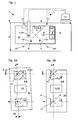
- FIG. 1 shows a plan view of a liquid handling system 4 with a robot arm 7 comprising a single seat 18, a substantially horizontal working field 6 and a device 1 according to the invention for positioning functional elements 2 and / or containers 3.
- This system 4 for working with fluid-containing samples 5 comprises a substantially horizontal working field 6 with a longitudinal extent X and a perpendicularly extending transverse extent Y.
- the robot arm 7 carries a substantially perpendicular to the working field 6 in a Z-direction aligned functional element 2 and can this functional element 2 at least in one Move portion 8 of the work area 6 in the X and / or Y and / or Z direction.
- the device 1 comprises two light barriers 9, 9 ', each crossing a transmitter 10, 10' and a receiver 11, 11 'within the subarea 8 of the working field 6.
- the scanning beams 12, 12 'of these light barriers each extend in a direction deviating from the X direction and / or from the Y direction.
- the scanning beams 12, 12 'of the light barriers 9, 9' preferably intersect at substantially an angle of 90 °, these scanning beams being essentially at an angle of 45 ° both in relation to the X direction and in relation to the Y direction ° (see Fig. 3) expand.
- the device comprises a computer 13 which detects the movements of the robot arm 7 or of the functional element 2 and which evaluates the signals of the receivers 11, 11 '. The computer 13 correlates these signals with the X / Y / Z position of that functional element 2 in the working field 6, which triggers these signals.
- the device may be integrated into a liquid handling system or comprise a plate 14 having the outer dimensions of a standard microplate 15.
- the device 1 can be fixed on a high-precision support 16 for standard microplates arranged within the working field 6.
- FIG. 2 shows a plan view of such a high-precision carrier or carrier 16 for microplates.
- the carrier 16 is still rotated in relation to the coordinate system of the liquid handling system.
- a plate 14 with a device 1 having the outer dimensions of a standard microplate 15 is fixed in a first position on a high precision support 16 for standard microplates located within the working field 6.
- the crossing point is preferably located outside the center of the plate, an operator is allowed by a rotated by 180 ° placing the plate 14 in the same place (the two light barriers are shown in Fig. 2A dotted) the orientation of the surface of the carrier to control along the X-extension of the working field 6 in the Z direction and correct if necessary by means of screws.
- a reference needle 21 is positioned on the robot arm 7 at the intersection point of the scanning beams 12, 12 'of the light barriers 9, 9', then the X, Y and Z values of this first reference point are stored in the computer 13.
- the movements of the robot arm 7 or of the functional element 2 are detected by a computer 13, which evaluates the signals of the receivers 11, 11 'and correlates these signals with the X / Y / Z position of that functional element 2 in the working field 6, which signals triggers.
- the plate 14 with the device 1 is fixed thereon in a second position on the same high-precision support 16 for standard microplates 15 (see Fig. 2A, lower position).
- the robot arm 7 is positioned with the reference needle 21 at the theoretical crossing point of the scanning beams 12, 12 'of the light barriers 9, 9', where it is located at the intersection point of the two light barriers by the amount of the error ⁇ X.
- the high-precision carrier 16 is so far moved in the X or Z direction until the reference needle 21 at the intersection of the scanning beams 12,12 'of the light barriers 9,9' is (see Fig. 2B).
- the carrier 16 is now aligned.
- the alignment of the surface of the carrier along the X-extension of the working field 6 in the Z-direction can be checked again and corrected by means of adjusting screws
- This method is used to position containers 3 in a system 4 for working with fluid-containing samples 5.
- the system 4 comprises a substantially horizontal working field 6 with a longitudinal extent X and a perpendicularly extending transverse extent Y and at least one robot arm 7 with at least one
- the functional element 2 (in this case a reference needle 21) is connected to the robot arm 7 at least in a subregion 8 of the working field 6 in X and / or Y and / or Z direction. Direction moves.
- At least one device 1 is arranged so that two light barriers 9,9 ', each with a transmitter 10,10' and a receiver 11,11 'intersect within the sub-area 8 of the working field 6; the scanning beams 12, 12 'of the light barriers 9, 9' extend in each case in a direction deviating from the X direction and / or from the Y direction. It is particularly preferred that the scanning beams 12, 12 'of the light barriers 9, 9' intersect at substantially an angle of 90 ° and are substantially at an angle of both in relation to the X direction and in relation to the Y direction Extend 45 °
- the transmitters 10, 10 'and the receivers 11, 11' of the light barriers 9, 9 ' are each arranged in a tunnel 17. This reduces the disruptive influence of laboratory lighting or daylight. If in each case a device 1: mounted on the first and third place for receiving a microplate on a carrier, the alignment of the carrier 16 can be accelerated. It can also be provided (not shown) that a plate 14 has four light barriers, which are switchable so that only two intersecting light barriers are active.
- a system 4 for working with fluid-containing samples 5, which comprises at least one device 1 just described, is preferred.
- Preferred functional elements here are pipette or dispenser tips 20.
- These seats 18 comprise correction elements 19, which are used to apply a force to each functional element 2 and thus to correct the position of each functional element 2 in its seat 18 in X and / or Y positions. and / or Z-direction are formed.
- these correction elements 19,19 ' act in a direction on the functional elements 2, which coincides either with the extension direction of the scanning beam 12 of the first photoelectric sensor 9 or with the extension direction of the scanning beam 12' of the second photoelectric sensor 9 '.
- correction elements 19, 19 ' are preferably designed as screws or piezoelements.
- grub screws with hexagon socket have proven particularly useful.
- Piezo elements have the advantage over the screws that the adjustment of the position of the corresponding functional element 2, so e.g. a pipette tip, could be corrected automatically.
- the higher production costs and the smaller adjustment paths could be regarded as disadvantageous with piezo elements.
- Each seat 18 for a functional element 2 comprises, in a more complex embodiment, four correction elements 19, 19 ', 19 ", 19”' of which two and two are respectively opposite to each other and complementary in their effect. It is particularly preferred that the adjustment direction of these correction elements 19, 19 ', 19 ", 19”' coincide with one extension direction of the scanning beams 12, 12 'of a light barrier 9, 9' of the device 1 according to the invention. It has been shown that in most cases a determination of the functional element 2 by tightening the the adjusted correction elements 19,19 'opposite screws or piezo elements 19 ", 19”' can be dispensed with. However, it can sometimes be necessary, so that additional time must be expended for this determination. As a compromise solution with which the locking time can be saved, a seat 18 is provided as a simpler embodiment, in which each correction element 19, 19 'is assigned a counteracting spring 22, 22' (compare FIG. 4).
- the pipette or dispenser tips 20 to be aligned are sequentially brought into a correcting position (black circular disk in Fig. 3). From this correction position, the pipette or dispenser tips 20 are adjusted by means of activation of the corresponding correction elements 19, 19 'by their individual correction values (white or black arrow in FIG. 3) until the tips 20 reach their end position at the intersection point of the scanning beams 12 , 12 'of the light barriers 9, 9' (dashed circle in FIG. 3) occupy.
- this method can be controlled by the computer 13 and run automatically. If simple grub screws are used as correction elements 19, 19 ', the adjustment process can be monitored with the computer and an acoustic signal can be triggered when interrupting the light barriers 9, 9', which indicates to the surgeon that the end of the individual correction value has been reached.
- the device 1 may also be used to control the current position of pipette or dispenser tips 20. Prior to performing liquid handling work, this is preferably done by placing a plate 14 with the intersecting light barriers 9, 9 'on a high precision carrier or carrier 16. Thereafter, the position of the individual, in a robotic arm inserted functional elements 2 and also the position of the carrier 16 tested in one pass and - if necessary - held on a computer file. The printout of such a file can be attached to the pipetting or dispenser protocol. Before executing the liquid handling, the plate 14 is removed again. The laying and removal of the plate 14 is preferably carried out manually by another robot arm (not shown) automatically or by an operator.
- the current position of pipette or dispenser tips 20 can be checked.
- the current top position can be checked at any time or sporadically. If a previously determined error value in the position is exceeded, then a warning signal can be issued, a corresponding protocol can be created or even the liquid handling process can be stopped.
- piezoelectric elements 19, 19 ' it is also possible to readjust the position of the tips 20 during the execution of a longer-lasting liquid handling process.
Claims (20)
- Plaque (14) destinée à une utilisation lors du positionnement d'éléments fonctionnels (2) et/ou de conteneurs (3) dans un système de laboratoire (4) destiné au travail avec des échantillons contenant un fluide (5), dans lequel le système de laboratoire (4) comprend une zone de travail (6) essentiellement horizontale présentant une longueur (X) et une largeur (Y) s'étendant perpendiculairement à celle-ci, ainsi qu'au moins un bras robotisé (7) comportant au moins un élément fonctionnel (2) aligné essentiellement verticalement par rapport à la zone de travail (6), dans une direction (Z), où le bras robotisé (7) peut déplacer l'élément fonctionnel (2) au moins dans une zone partielle (8) de la zone de travail (6) au moins dans une direction X ou Y ou Z, ces directions (X, Y, Z) définissant un système de coordonnées orthogonal pour les déplacements du bras robotisé et/ou des éléments fonctionnels (2); et la plaque (14) pouvant être positionnée au sein de la zone partielle (8) de la zone de travail (6) et comprenant deux barrières photoélectriques (9,9') qui se croisent, avec respectivement un émetteur (10,10') et un récepteur (11,11'), caractérisée en ce que la plaque (14) présente les dimensions externes d'une plaque de microtitration standard (15) et peut être fixée, en position précise, sur un support haute précision(16) de plaques de microtitration standard, disposé au sein de la zone de travail (6), les barrières photoélectriques (9,9') étant disposées sur la plaque (14) de façon telle que les directions de rayonnement des deux faisceaux d'exploration (12,12') ne s'étendent pas parallèlement aux arêtes externes de la plaque (14).
- Plaque (14) selon la revendication 1, caractérisée en ce que les faisceaux d'exploration (12,12') des barrières photoélectriques (9,9') se coupent essentiellement selon un angle de 90° et forment avec les arêtes externes de la plaque (14) essentiellement un angle de 45°.
- Plaque (14) selon l'une des revendications 1 ou 2, caractérisée en ce que les émetteurs (10,10') et les récepteurs (11,11') des barrières photoélectriques (9,9') sont respectivement disposés dans un tunnel (17).
- Plaque (14) selon l'une des revendications précédentes, caractérisée en ce que les deux barrières photoélectriques (9,9') sont disposées sur cette plaque (14) de façon telle que les faisceaux d'exploration (12,12') des barrières photoélectriques (9,9') se coupent en un point qui se trouve dans une position définie par rapport au puits A1 d'une plaque de microtitration standard (15).
- Plaque (14) selon la revendication 4, caractérisée en ce que le point d'intersection des faisceaux d'exploration (12,12') des barrières photoélectriques (9,9') se trouve hors du milieu de la plaque (14).
- Système de laboratoire (4) permettant de travailler avec des échantillons contenant du fluide (5), qui comprend un ordinateur (13) qui commande un bras robotisé (7), caractérisé en ce qu'il comprend au moins une plaque (14) selon l'une des revendications précédentes, l'ordinateur (13) enregistrant les déplacements du bras robotisé (7) et/ou de l'élément fonctionnel (2) et évaluant les signaux des récepteurs (11,11').
- Système de laboratoire (4) selon la revendication 6, caractérisé en ce que l'ordinateur (13) corrèle ces signaux à la position X/Y/Z de chaque élément fonctionnel (2) de la zone de travail (6) qui déclenche ces signaux.
- Système de laboratoire (4) selon la revendication 6 ou 7, comportant un bras robotisé (7) qui comprend un logement unique (18) ou plusieurs logements (18) d'éléments fonctionnels (2), ces logements (18) comportant des éléments de correction (19) qui sont exécutés pour exercer une force sur chaque élément fonctionnel (2) et par conséquent pour corriger la position de chaque élément fonctionnel (2) dans son logement (18) dans au moins une direction X ou Y ou Z, caractérisé en ce que ces éléments de correction (19,19',19",19"') agissent sur les éléments fonctionnels (2) dans une direction qui concorde avec la direction du faisceau d'exploration (12) de la première barrière photoélectrique (9) ou avec la direction du faisceau d'exploration (12') de la seconde barrière photoélectrique (9').
- Système de laboratoire (4) selon la revendication 8, caractérisé en ce que ces éléments fonctionnels (2) sont exécutés en tant que pointes de pipette ou de distributeur (20) pouvant être levées et abaissées dans la direction Z, ou en tant qu'aiguilles de référence (21).
- Système de laboratoire (4) selon l'une des revendications 8 ou 9, caractérisé en ce que ces éléments de correction (19) sont exécutés en tant que vis ou éléments piézo-électriques.
- Système de laboratoire (4) selon l'une des revendications 8 à 10, caractérisé en ce qu'à chaque élément de correction (19) est coordonné un ressort de réaction (22).
- Système de laboratoire (4) selon l'une des revendications 8 à 11, caractérisé en ce que chaque logement (18) d'un élément fonctionnel (2) comprend quatre éléments de correction (19), lesquels sont respectivement opposés deux à deux et se complètent dans leur action.
- Procédé d'alignement de récipients (3) sur une zone de travail (6) d'un système de laboratoire (4) destiné à travailler avec des échantillons contenant des fluides (5), dans lequel le système de laboratoire (4) comprend une zone de travail (6) essentiellement horizontale présentant une longueur (X) et une largeur (Y) s'étendant perpendiculairement à celle-ci, ainsi qu'au moins un bras robotisé (7) comportant au moins un élément fonctionnel (2) aligné essentiellement verticalement par rapport à la zone de travail (6), dans une direction (Z), le bras robotisé (7) pouvant déplacer l'élément fonctionnel (2) au moins dans une zone partielle (8) de la zone de travail (6) au moins dans une direction X ou Y ou Z, ces directions (X, Y, Z) définissant un système de coordonnées orthogonal pour les déplacements du bras robotisé et/ou des éléments fonctionnels, procédé dans lequel une plaque (14), qui comprend deux barrières photoélectriques (9,9') qui se coupent avec respectivement un émetteur (10,10') et un récepteur (11,11'), est positionnée au sein d'une zone partielle (8) de la zone de travail (6), caractérisé en ce que la plaque (14) présente les dimensions externes d'une plaque de microtitration standard (15) et peut être fixée, en position précise, sur un support haute précision (16) de plaques de microtitration standard, disposé au sein de la zone de travail (6), les barrières photoélectriques (9,9') étant disposées sur la plaque (14) de façon telle que les directions de rayonnement des deux faisceaux d'exploration (12,12') ne s'étendent pas parallèlement aux arêtes externes de la plaque (14).
- Procédé selon la revendication 13, caractérisé en ce que les faisceaux d'exploration (12,12') des barrières photoélectriques (9,9') se coupent essentiellement en formant un angle de 90° et forment avec les arêtes externes de la plaque (14) essentiellement un angle de 45°.
- Procédé selon la revendication 13 ou 14, caractérisé en ce que les déplacements du bras robotisé (7) et/ou de l'élément fonctionnel (2) sont enregistrés par un ordinateur (13) qui évalue les signaux des récepteurs (11,11') et corrèle ces signaux avec la position X/Y de chaque élément fonctionnel (2) de la zone de travail (6) qui déclenche ces signaux.
- Procédé selon l'une des revendications 13 à 15, caractérisé en ce qu'avec le bras robotisé (7), une aiguille de référence (21) est positionnée au point d'intersection des faisceaux d'exploration (12,12') des barrières photoélectriques (9,9') et en ce que les valeurs X, Y et Z de ce premier point de référence sont mémorisées dans l'ordinateur.
- Procédé selon la revendication 16, caractérisé en ce que la plaque (14) est fixée dans une seconde position sur le même support haute précision (16) de plaques de microtitration standard (15), en ce que le bras robotisé (7) est positionné avec l'aiguille de référence (21) dans le point d'intersection théorique des faisceaux d'exploration (12,12') des barrières photoélectriques (9,9') et en ce que le support haute précision (16) est déplacé dans la direction X ou Z jusqu'à ce que l'aiguille de référence (21) se trouve au point d'intersection des faisceaux d'exploration (12,12') des barrières photoélectriques (9,9').
- Procédé d'alignement de pointes de pipette ou de distributeur (20) sur un récipient (3), en particulier sur les puits (23) d'une plaque de microtitration standard (15) disposée dans la zone de travail (6) d'un système de laboratoire (4), caractérisé en ce que le récipient (3) est aligné selon le procédé selon la revendication 17, et en ce que toutes les pointes de pipette ou de distributeur (20) à aligner sont déplacées dans la direction X ou Y par les deux barrières photoélectriques (9,9'), chaque interruption des faisceaux d'exploration (12,12') enregistrant les valeurs X et Y des pointes de pipette ou de distributeur (20) correspondantes et les mémorisant dans l'ordinateur (13).
- Procédé selon la revendication 18, caractérisé en ce que les premières et secondes valeurs de correction découlant des valeurs X et Y mémorisées sont calculées pour chacune des pointes de pipette ou de distributeur (20) à aligner, et en ce que les pointes de pipette ou de distributeur (20) à aligner sont amenées les unes après les autres dans une position de correction à partir de laquelle, au moyen de l'activation des éléments de correction (19) correspondants, les pointes de pipette ou de distributeur (20) sont décalées de leurs valeurs de correction individuelles jusqu'à adopter leur position finale dans le point d'intersection des faisceaux d'exploration (12,12') des barrières photoélectriques (9,9').
- Procédé selon l'une des revendications 13 à 19, caractérisé en ce qu'il est commandé par un ordinateur (13) et se déroule automatiquement.
Applications Claiming Priority (2)
| Application Number | Priority Date | Filing Date | Title |
|---|---|---|---|
| CH10802003 | 2003-06-20 | ||
| CH10802003 | 2003-06-20 |
Publications (2)
| Publication Number | Publication Date |
|---|---|
| EP1489425A1 EP1489425A1 (fr) | 2004-12-22 |
| EP1489425B1 true EP1489425B1 (fr) | 2007-02-14 |
Family
ID=33315349
Family Applications (1)
| Application Number | Title | Priority Date | Filing Date |
|---|---|---|---|
| EP04013819A Not-in-force EP1489425B1 (fr) | 2003-06-20 | 2004-06-11 | Dispositif et méthode pour positionner des éléments fonctionnels et/ou des récipients sur la surface de travail d'un manipulateur de laboratoire à l'aide de deux barrières optiques se croisant |
Country Status (3)
| Country | Link |
|---|---|
| US (1) | US7529598B2 (fr) |
| EP (1) | EP1489425B1 (fr) |
| DE (1) | DE502004002881D1 (fr) |
Families Citing this family (17)
| Publication number | Priority date | Publication date | Assignee | Title |
|---|---|---|---|---|
| US9312095B2 (en) * | 2010-03-24 | 2016-04-12 | Brown University | Method and system for automating sample preparation for microfluidic cryo TEM |
| DE102010037084A1 (de) * | 2010-08-20 | 2012-02-23 | LCTech GmbH | Probenaufbereitungssystem sowie ein Verfahren zur Bearbeitung einer Probe |
| US9266241B2 (en) | 2011-03-14 | 2016-02-23 | Matthew E. Trompeter | Robotic work object cell calibration system |
| WO2013122013A1 (fr) * | 2012-02-16 | 2013-08-22 | 株式会社日立ハイテクノロジーズ | Système d'ajustement d'un dispositif d'analyse automatique, et procédé associé |
| US20140304964A1 (en) * | 2013-04-12 | 2014-10-16 | Bio-Rad Laboratories, Inc. | Probe height fixture product profile |
| EP3484669A4 (fr) * | 2016-07-14 | 2019-08-07 | Siemens Healthcare Diagnostics Inc. | Procédés et appareil pour des ajustements de position dynamiques d'un dispositif de préhension de robot sur la base de données d'imagerie de porte-échantillon |
| JP6832418B2 (ja) * | 2016-07-21 | 2021-02-24 | シーメンス・ヘルスケア・ダイアグノスティックス・インコーポレーテッドSiemens Healthcare Diagnostics Inc. | 試験システムの位置合わせ自動化 |
| EP3745081B1 (fr) | 2019-05-28 | 2023-03-22 | Tecan Trading Ag | Détecteur de position et procédé de détermination tridimensionnelle de position |
| CN115151652A (zh) | 2020-02-25 | 2022-10-04 | Dna斯克瑞普特公司 | 用于酶促合成多核苷酸的方法和设备 |
| IL299164A (en) | 2020-06-16 | 2023-02-01 | Dna Script | Systems, devices and kits for the enzymatic synthesis of polynucleotides |
| JP2023015676A (ja) * | 2021-07-20 | 2023-02-01 | 横河電機株式会社 | 検出装置及び検出方法 |
| EP4206679A1 (fr) * | 2021-12-29 | 2023-07-05 | TECAN Trading AG | Lecteure optique pour embout de pipette |
| WO2023170286A2 (fr) | 2022-03-11 | 2023-09-14 | Dna Script | Montant d'alignement et mécanisme sécurisé pour synthèse enzymatique de polynucléotides |
| WO2023170258A1 (fr) | 2022-03-11 | 2023-09-14 | Dna Script | Appareil de synthèse enzymatique d'une pluralité de polynucléotides comprenant un piège à condensation |
| WO2023170266A1 (fr) | 2022-03-11 | 2023-09-14 | Dna Script | Station d'automatisation pour la synthèse enzymatique de polynucléotides |
| WO2023170259A1 (fr) | 2022-03-11 | 2023-09-14 | Dna Script | Support d'accessoire modulaire |
| CN116922449B (zh) * | 2023-09-13 | 2023-11-21 | 沈阳格熙科技有限公司 | 一种机器人定位精度检测装置 |
Citations (2)
| Publication number | Priority date | Publication date | Assignee | Title |
|---|---|---|---|---|
| EP0555739A1 (fr) * | 1992-02-13 | 1993-08-18 | F. Hoffmann-La Roche Ag | Dispositif automatique de pipettage |
| DE19754857A1 (de) * | 1996-12-18 | 1998-07-02 | Motoman Robotec Gmbh | Vorrichtung zum Bestimmen der Position des Schweißdrahtes oder der Elektrode eines Roboters |
Family Cites Families (14)
| Publication number | Priority date | Publication date | Assignee | Title |
|---|---|---|---|---|
| NL7210822A (fr) * | 1972-08-08 | 1974-02-12 | ||
| US4613803A (en) * | 1985-02-14 | 1986-09-23 | Kabushiki Kaisha Kobe Seiko Sho | Industrial robot and a method for positioning same |
| JPH0620097B2 (ja) * | 1987-10-20 | 1994-03-16 | 富士通株式会社 | ウエハ位置決め装置 |
| US4892993A (en) * | 1988-05-19 | 1990-01-09 | Aluminum Company Of America | Welding system for hollow thin walled members |
| US4932777A (en) * | 1988-09-30 | 1990-06-12 | The United States Of America As Represented By The Administrator Of The National Aeronautics And Space Administration | Electro-optical spin measurement system |
| JPH06170768A (ja) * | 1992-12-04 | 1994-06-21 | Meidensha Corp | ロボットの位置ずれ検出装置 |
| US5563798A (en) * | 1994-04-05 | 1996-10-08 | Applied Materials, Inc. | Wafer positioning system |
| US5905850A (en) * | 1996-06-28 | 1999-05-18 | Lam Research Corporation | Method and apparatus for positioning substrates |
| AU2041000A (en) * | 1998-12-02 | 2000-06-19 | Kensington Laboratories, Inc. | Specimen holding robotic arm end effector |
| DE19923222C2 (de) * | 1999-05-20 | 2001-11-22 | Jandratek Gmbh | Verfahren zum genauen Positionieren mindestens einer Pipette in einer Analyseeinrichtung |
| DE10013511A1 (de) * | 2000-03-20 | 2001-10-11 | Brand Gmbh & Co Kg | Mehrkanal-Pipettiereinrichtung sowie Pipettenschaft dafür |
| DE10230772A1 (de) | 2002-01-15 | 2003-07-31 | Thomas Pagel | Einmessvorrichtung und Verfahren zum Einmessen eines Arbeitspunktes von Werkzeugen für Industrieroboter |
| AU2003235693A1 (en) * | 2002-01-15 | 2003-07-30 | Johannes Kemp | Calibration device and method for calibrating a working point of tools for industrial robots |
| JP4235171B2 (ja) * | 2002-05-17 | 2009-03-11 | ジェン−プロウブ インコーポレイテッド | サンプルチューブブロッキング手段を備えるサンプルキャリアおよびそれと共に使用するためのドリップシールド |
-
2004
- 2004-06-11 EP EP04013819A patent/EP1489425B1/fr not_active Not-in-force
- 2004-06-11 DE DE502004002881T patent/DE502004002881D1/de active Active
- 2004-06-16 US US10/869,297 patent/US7529598B2/en not_active Expired - Fee Related
Patent Citations (2)
| Publication number | Priority date | Publication date | Assignee | Title |
|---|---|---|---|---|
| EP0555739A1 (fr) * | 1992-02-13 | 1993-08-18 | F. Hoffmann-La Roche Ag | Dispositif automatique de pipettage |
| DE19754857A1 (de) * | 1996-12-18 | 1998-07-02 | Motoman Robotec Gmbh | Vorrichtung zum Bestimmen der Position des Schweißdrahtes oder der Elektrode eines Roboters |
Also Published As
| Publication number | Publication date |
|---|---|
| EP1489425A1 (fr) | 2004-12-22 |
| US20040267405A1 (en) | 2004-12-30 |
| DE502004002881D1 (de) | 2007-03-29 |
| US7529598B2 (en) | 2009-05-05 |
Similar Documents
| Publication | Publication Date | Title |
|---|---|---|
| EP1489425B1 (fr) | Dispositif et méthode pour positionner des éléments fonctionnels et/ou des récipients sur la surface de travail d'un manipulateur de laboratoire à l'aide de deux barrières optiques se croisant | |
| EP0555739B1 (fr) | Dispositif automatique de pipettage | |
| WO2018015545A1 (fr) | Procédé pour déterminer la position d'un bras robotisé dans un système de manipulation de liquide et système de manipulation de liquide correspondant | |
| EP1738179B1 (fr) | Dispositif pour transporter ou examiner des liquides | |
| EP0332864B1 (fr) | Procédé de micro-injection dans des cellules vivantes et appareillage pour la mise en oeuvre du procédé | |
| EP3452833B1 (fr) | Procédé pour déterminer la position d'un bras robotisé dans un système de manipulation de liquide et système de manipulation de liquide correspondant | |
| DE10254229B4 (de) | Positioniervorrichtung zum Positionieren einerAuffangvorrichtung eines Laser-Mikrodissektionssystems | |
| WO2009046786A1 (fr) | Procédé pour déterminer une position focale et procédé pour déterminer la position d'un rayon laser par rapport à une ouverture, et buse d'usinage laser | |
| DE102015013498B4 (de) | Positionserfassungssystem zum Erfassen einer Position eines Gegenstands | |
| WO2018177790A1 (fr) | Dispositif et procédé servant à retirer une partie de pièce d'une pièce restante | |
| WO2004052591A1 (fr) | Dispositif porte-outil et procédé pour positionner un outil | |
| EP3501655B1 (fr) | Système de distribution d'échantillons et procédé de distribution d'échantillons | |
| WO2018130313A1 (fr) | Procédé de commande d'une machine-outil | |
| DE102009050521B4 (de) | Thermisches Materialbearbeitungsverfahren | |
| EP2350676A2 (fr) | Dispositif d'analyse automatisé présentant un dispositif automatique de prélèvement par pipette et un bras de prélèvement par pipette muni d'un détecteur d'impact | |
| WO2017001676A1 (fr) | Système de pipetage muni d'un dispositif de traitement d'images | |
| DE19923222C2 (de) | Verfahren zum genauen Positionieren mindestens einer Pipette in einer Analyseeinrichtung | |
| EP2158999B1 (fr) | Dispositif de mesure et/ou de réglage d'un outil | |
| EP3924135A1 (fr) | Procédé d'installation d'une machine-outil et système de fabrication | |
| DE19507227C1 (de) | Verfahren zum Kalibrieren des Arbeitspunktes eines automatisch in einem kartesischen Koordinatensystem bewegbaren Werkzeuges | |
| DE102018105922B4 (de) | Anordnung zur Erfassung der Relativlage eines Messkopfes | |
| EP3647714A1 (fr) | Dispositif capteur, dispositif de captage, procédé de détermination et procédé de captage permettant de déterminer une position relative ou de capter un objet dans l'espace | |
| DE102018206232A1 (de) | Verfahren zum Detektieren einer Fehlstellung einer Schneidoptik einer Laserschneidmaschine, Auswerteeinrichtung und Laserschneidmaschine | |
| EP0292426A2 (fr) | Appareil pour la détermination de la position d'un corps manifestant une symétrie de rotation, par rapport à un axe de référence | |
| DE19816051A1 (de) | Verfahren zur Schweißkopfpositionierung |
Legal Events
| Date | Code | Title | Description |
|---|---|---|---|
| PUAI | Public reference made under article 153(3) epc to a published international application that has entered the european phase |
Free format text: ORIGINAL CODE: 0009012 |
|
| AK | Designated contracting states |
Kind code of ref document: A1 Designated state(s): AT BE BG CH CY CZ DE DK EE ES FI FR GB GR HU IE IT LI LU MC NL PL PT RO SE SI SK TR |
|
| AX | Request for extension of the european patent |
Extension state: AL HR LT LV MK |
|
| 17P | Request for examination filed |
Effective date: 20050120 |
|
| 17Q | First examination report despatched |
Effective date: 20050314 |
|
| AKX | Designation fees paid |
Designated state(s): CH DE FR GB LI |
|
| RTI1 | Title (correction) |
Free format text: DEVICE AND METHOD FOR POSITIONING FUNCTIONAL ELEMENTS AND/OR VESSELS ON THE WORK SPACE OF A LABORATORY MANIPULATOR BY THE HELP OF TWO CROSSING LIGHT BARRIERS |
|
| GRAP | Despatch of communication of intention to grant a patent |
Free format text: ORIGINAL CODE: EPIDOSNIGR1 |
|
| GRAS | Grant fee paid |
Free format text: ORIGINAL CODE: EPIDOSNIGR3 |
|
| GRAA | (expected) grant |
Free format text: ORIGINAL CODE: 0009210 |
|
| AK | Designated contracting states |
Kind code of ref document: B1 Designated state(s): CH DE FR GB LI |
|
| REG | Reference to a national code |
Ref country code: GB Ref legal event code: FG4D Free format text: NOT ENGLISH |
|
| RIN1 | Information on inventor provided before grant (corrected) |
Inventor name: LEEMANN, JOAS Inventor name: FISCH, PETER Inventor name: STREBEL, CHRISTIAN Inventor name: INGENHOVEN, NIKOLAUS |
|
| REG | Reference to a national code |
Ref country code: CH Ref legal event code: EP |
|
| REF | Corresponds to: |
Ref document number: 502004002881 Country of ref document: DE Date of ref document: 20070329 Kind code of ref document: P |
|
| REG | Reference to a national code |
Ref country code: CH Ref legal event code: NV Representative=s name: OK PAT AG PATENTE MARKEN LIZENZEN |
|
| GBT | Gb: translation of ep patent filed (gb section 77(6)(a)/1977) |
Effective date: 20070418 |
|
| ET | Fr: translation filed | ||
| PLBE | No opposition filed within time limit |
Free format text: ORIGINAL CODE: 0009261 |
|
| STAA | Information on the status of an ep patent application or granted ep patent |
Free format text: STATUS: NO OPPOSITION FILED WITHIN TIME LIMIT |
|
| 26N | No opposition filed |
Effective date: 20071115 |
|
| REG | Reference to a national code |
Ref country code: FR Ref legal event code: PLFP Year of fee payment: 13 |
|
| REG | Reference to a national code |
Ref country code: FR Ref legal event code: PLFP Year of fee payment: 14 |
|
| REG | Reference to a national code |
Ref country code: FR Ref legal event code: PLFP Year of fee payment: 15 |
|
| PGFP | Annual fee paid to national office [announced via postgrant information from national office to epo] |
Ref country code: DE Payment date: 20200527 Year of fee payment: 17 Ref country code: FR Payment date: 20200512 Year of fee payment: 17 Ref country code: CH Payment date: 20200528 Year of fee payment: 17 |
|
| PGFP | Annual fee paid to national office [announced via postgrant information from national office to epo] |
Ref country code: GB Payment date: 20200603 Year of fee payment: 17 |
|
| REG | Reference to a national code |
Ref country code: CH Ref legal event code: PFUS Owner name: TECAN TRADING AG, CH Free format text: FORMER OWNER: TECAN TRADING AG, CH |
|
| REG | Reference to a national code |
Ref country code: DE Ref legal event code: R119 Ref document number: 502004002881 Country of ref document: DE |
|
| REG | Reference to a national code |
Ref country code: CH Ref legal event code: PL |
|
| GBPC | Gb: european patent ceased through non-payment of renewal fee |
Effective date: 20210611 |
|
| PG25 | Lapsed in a contracting state [announced via postgrant information from national office to epo] |
Ref country code: LI Free format text: LAPSE BECAUSE OF NON-PAYMENT OF DUE FEES Effective date: 20210630 Ref country code: GB Free format text: LAPSE BECAUSE OF NON-PAYMENT OF DUE FEES Effective date: 20210611 Ref country code: DE Free format text: LAPSE BECAUSE OF NON-PAYMENT OF DUE FEES Effective date: 20220101 Ref country code: CH Free format text: LAPSE BECAUSE OF NON-PAYMENT OF DUE FEES Effective date: 20210630 |
|
| PG25 | Lapsed in a contracting state [announced via postgrant information from national office to epo] |
Ref country code: FR Free format text: LAPSE BECAUSE OF NON-PAYMENT OF DUE FEES Effective date: 20210630 |