EP3501655B1 - Système de distribution d'échantillons et procédé de distribution d'échantillons - Google Patents
Système de distribution d'échantillons et procédé de distribution d'échantillons Download PDFInfo
- Publication number
- EP3501655B1 EP3501655B1 EP18215662.0A EP18215662A EP3501655B1 EP 3501655 B1 EP3501655 B1 EP 3501655B1 EP 18215662 A EP18215662 A EP 18215662A EP 3501655 B1 EP3501655 B1 EP 3501655B1
- Authority
- EP
- European Patent Office
- Prior art keywords
- sensor unit
- pipette tips
- pipette
- unit
- light
- Prior art date
- Legal status (The legal status is an assumption and is not a legal conclusion. Google has not performed a legal analysis and makes no representation as to the accuracy of the status listed.)
- Active
Links
- 238000000034 method Methods 0.000 title claims description 44
- 238000001514 detection method Methods 0.000 claims description 32
- 230000004888 barrier function Effects 0.000 claims description 7
- 108010076504 Protein Sorting Signals Proteins 0.000 claims description 6
- 230000001154 acute effect Effects 0.000 claims description 6
- 230000003213 activating effect Effects 0.000 claims description 3
- 230000008859 change Effects 0.000 claims description 3
- 238000006073 displacement reaction Methods 0.000 claims description 3
- 230000008569 process Effects 0.000 description 16
- 239000007788 liquid Substances 0.000 description 12
- 239000002699 waste material Substances 0.000 description 12
- 238000011161 development Methods 0.000 description 10
- 230000018109 developmental process Effects 0.000 description 10
- 238000012360 testing method Methods 0.000 description 10
- 230000007246 mechanism Effects 0.000 description 8
- 238000011156 evaluation Methods 0.000 description 6
- 238000012544 monitoring process Methods 0.000 description 4
- 238000011109 contamination Methods 0.000 description 3
- 238000012864 cross contamination Methods 0.000 description 2
- 230000001419 dependent effect Effects 0.000 description 2
- 238000005259 measurement Methods 0.000 description 2
- 238000005457 optimization Methods 0.000 description 2
- 230000004913 activation Effects 0.000 description 1
- 238000005352 clarification Methods 0.000 description 1
- 238000013461 design Methods 0.000 description 1
- 238000003780 insertion Methods 0.000 description 1
- 230000037431 insertion Effects 0.000 description 1
- 238000012545 processing Methods 0.000 description 1
- 208000008918 voyeurism Diseases 0.000 description 1
Images

Classifications
-
- G—PHYSICS
- G01—MEASURING; TESTING
- G01N—INVESTIGATING OR ANALYSING MATERIALS BY DETERMINING THEIR CHEMICAL OR PHYSICAL PROPERTIES
- G01N35/00—Automatic analysis not limited to methods or materials provided for in any single one of groups G01N1/00 - G01N33/00; Handling materials therefor
- G01N35/10—Devices for transferring samples or any liquids to, in, or from, the analysis apparatus, e.g. suction devices, injection devices
- G01N35/1065—Multiple transfer devices
-
- B—PERFORMING OPERATIONS; TRANSPORTING
- B01—PHYSICAL OR CHEMICAL PROCESSES OR APPARATUS IN GENERAL
- B01L—CHEMICAL OR PHYSICAL LABORATORY APPARATUS FOR GENERAL USE
- B01L3/00—Containers or dishes for laboratory use, e.g. laboratory glassware; Droppers
- B01L3/02—Burettes; Pipettes
- B01L3/021—Pipettes, i.e. with only one conduit for withdrawing and redistributing liquids
- B01L3/0213—Accessories for glass pipettes; Gun-type pipettes, e.g. safety devices, pumps
-
- B—PERFORMING OPERATIONS; TRANSPORTING
- B01—PHYSICAL OR CHEMICAL PROCESSES OR APPARATUS IN GENERAL
- B01L—CHEMICAL OR PHYSICAL LABORATORY APPARATUS FOR GENERAL USE
- B01L3/00—Containers or dishes for laboratory use, e.g. laboratory glassware; Droppers
- B01L3/02—Burettes; Pipettes
- B01L3/0275—Interchangeable or disposable dispensing tips
-
- B—PERFORMING OPERATIONS; TRANSPORTING
- B01—PHYSICAL OR CHEMICAL PROCESSES OR APPARATUS IN GENERAL
- B01L—CHEMICAL OR PHYSICAL LABORATORY APPARATUS FOR GENERAL USE
- B01L3/00—Containers or dishes for laboratory use, e.g. laboratory glassware; Droppers
- B01L3/02—Burettes; Pipettes
- B01L3/021—Pipettes, i.e. with only one conduit for withdrawing and redistributing liquids
- B01L3/0217—Pipettes, i.e. with only one conduit for withdrawing and redistributing liquids of the plunger pump type
- B01L3/0237—Details of electronic control, e.g. relating to user interface
-
- G—PHYSICS
- G01—MEASURING; TESTING
- G01N—INVESTIGATING OR ANALYSING MATERIALS BY DETERMINING THEIR CHEMICAL OR PHYSICAL PROPERTIES
- G01N21/00—Investigating or analysing materials by the use of optical means, i.e. using sub-millimetre waves, infrared, visible or ultraviolet light
- G01N21/17—Systems in which incident light is modified in accordance with the properties of the material investigated
- G01N21/55—Specular reflectivity
- G01N21/552—Attenuated total reflection
- G01N21/553—Attenuated total reflection and using surface plasmons
-
- G—PHYSICS
- G01—MEASURING; TESTING
- G01N—INVESTIGATING OR ANALYSING MATERIALS BY DETERMINING THEIR CHEMICAL OR PHYSICAL PROPERTIES
- G01N35/00—Automatic analysis not limited to methods or materials provided for in any single one of groups G01N1/00 - G01N33/00; Handling materials therefor
- G01N35/00584—Control arrangements for automatic analysers
-
- G—PHYSICS
- G01—MEASURING; TESTING
- G01N—INVESTIGATING OR ANALYSING MATERIALS BY DETERMINING THEIR CHEMICAL OR PHYSICAL PROPERTIES
- G01N35/00—Automatic analysis not limited to methods or materials provided for in any single one of groups G01N1/00 - G01N33/00; Handling materials therefor
- G01N35/10—Devices for transferring samples or any liquids to, in, or from, the analysis apparatus, e.g. suction devices, injection devices
- G01N35/1081—Devices for transferring samples or any liquids to, in, or from, the analysis apparatus, e.g. suction devices, injection devices characterised by the means for relatively moving the transfer device and the containers in an horizontal plane
- G01N35/109—Devices for transferring samples or any liquids to, in, or from, the analysis apparatus, e.g. suction devices, injection devices characterised by the means for relatively moving the transfer device and the containers in an horizontal plane with two horizontal degrees of freedom
-
- B—PERFORMING OPERATIONS; TRANSPORTING
- B01—PHYSICAL OR CHEMICAL PROCESSES OR APPARATUS IN GENERAL
- B01L—CHEMICAL OR PHYSICAL LABORATORY APPARATUS FOR GENERAL USE
- B01L2200/00—Solutions for specific problems relating to chemical or physical laboratory apparatus
- B01L2200/14—Process control and prevention of errors
- B01L2200/143—Quality control, feedback systems
-
- G—PHYSICS
- G01—MEASURING; TESTING
- G01N—INVESTIGATING OR ANALYSING MATERIALS BY DETERMINING THEIR CHEMICAL OR PHYSICAL PROPERTIES
- G01N35/00—Automatic analysis not limited to methods or materials provided for in any single one of groups G01N1/00 - G01N33/00; Handling materials therefor
- G01N35/00584—Control arrangements for automatic analysers
- G01N35/00722—Communications; Identification
- G01N35/00732—Identification of carriers, materials or components in automatic analysers
- G01N2035/00742—Type of codes
- G01N2035/00772—Type of codes mechanical or optical code other than bar code
Definitions
- the invention relates to a sample distribution system according to the preamble of claim 1 and a method for distributing samples according to the preamble of claim 10.
- Sample distribution systems are known in the art and are typically used in laboratories. These sample distribution systems usually work with pipettes that are used to dose liquids. There are automated pipette systems and hand-held and/or hand-operated pipettes. All of these devices have a sample container in which a mostly liquid sample to be pipetted is received and from which it can be released again.
- a sample can be taken up and released by, for example, generating a negative pressure in the sample container to take up the sample and an overpressure to release the sample.
- piston pipettes have, for example, a movable piston, with an air column being arranged between the sample to be pipetted and the piston. When the piston moves in a first direction, the piston displaces the air column, while when it moves in a second direction opposite to the first direction, it pulls the air column and thus also the sample to be pipetted into the sample container.
- pipettes can be equipped with exchangeable sample containers in the form of pipette tips.
- the pipette then has a connecting section onto which the pipette tip can be placed and from which it can be removed again after use.
- the pipette tip usually has two openings, with the connecting section being received in the larger of the two openings and closing it when it is pushed on. The sample is taken up and released through the smaller opening. Since only the pipette tip comes into contact with the sample to be pipetted, contamination during subsequent pipetting processes is prevented.
- the pipette tip is usually a disposable plastic item.
- pipettes can have one (in the case of single-channel pipettes) or several (in the case of multi-channel pipettes) connecting sections.
- Several connecting sections each of which can be equipped with an exchangeable pipette tip, allow several samples to be taken up and dispensed at the same time.
- the release mechanisms used usually have some things in common. This includes a slider that is designed to be movable along the connecting section. When the ejection mechanism is actuated, the slide is moved in the direction of the pipette tip, comes into contact with it and pushes it off the connecting section in the opposite direction to the push-on direction.
- the ejection mechanism can often be actuated manually by means of an operating element.
- automated release mechanisms are also known, which are operated, for example, by electrical or pneumatic drives.
- a force is mechanically transmitted to the slide in order to cause its movement in the direction of the pipette tip.
- the part of the ejector mechanism that makes the connection between the control or drive and the pusher can be designed in a variety of ways, but generally has one or more movable members.
- the movement of the links is linked to the movement of the slide.
- the members are expediently designed to transmit the force exerted on the operating element when it is actuated or the force exerted by the drive on the slide.
- the EP-A-0 114 686 describes an apparatus and method for handling liquid samples that helps avoid cross-contamination or errors in handling small liquid samples during filling, transferring, or mixing such liquid samples through repeated use of the same pipette.
- a means for detaching the tip member from the cylinder so that another pipette tip member can be changed selectively and automatically after each insertion into the liquid in a sample container, to avoid cross-contamination when successive samples are transferred by residual liquid at a To prevent pipette tip element.
- a sensor on the device in order to be able to determine whether or not pipette tips have been received at all connecting sections.
- an LED diode is arranged on one side and a receiver on the other side of the table in the direction of the row of pipettes.
- the WO 02/16036 discloses a robotic pipetting head provided with multiple pipette tips. It has a connecting part that can be rigidly attached to a robot arm and a pipette part to which a plurality of pipette tips can be attached.
- the pipette head with the pipette adapters is lowered through openings provided in a separate plate. A light barrier is assigned to each opening below the plate. If no pipette tip is attached to a pipette adapter, this is detected by one of the many light barriers. If, on the other hand, it is determined that there are pipette tips on all pipette adapters, the pipette head is released for pipetting.
- the ejection mechanism is to be improved in such a way that the correct ejection of the pipette tips can be reliably monitored and accordingly errors during ejection can be reliably detected.
- This object is achieved by a sample distribution system having the features of claim 1.
- Advantageous refinements are described in the dependent claims 2-9.
- this object is achieved by a method having the features of claim 10.
- Advantageous developments of the method are described in the dependent claims 11-15.
- the pipetting process is to be understood as meaning the taking up, in particular, of a liquid in pipettes and the distribution or dispensing of the liquid on a sample container, which generally has a large number of small pots.
- the sample distribution system according to the invention and the method according to the invention are able to look at the pipetting unit from the outside and can therefore advantageously determine whether a pipette tip has been properly ejected or not.
- the shape and position of the pipette tips can be checked, in particular relative to the pipette unit.
- the sensor unit and the pipette unit are designed to be movable relative to one another in order to determine the presence of a pipette tip when this is located in the detection area of the sensor unit.
- a counter can be assigned to the sensor unit in order to determine the number of pipette tips.
- the detection area of the sensor unit is formed by a single light beam or light pulse.
- light barriers which are designed as light grids and which use a plurality of light beams for detection.
- the individual pipette tips are scanned with the light beam, i.e. the light beam is moved relative to the pipette tips. For example, if the light beam hits a pipette tip directly, the beam is not reflected back and a dark spot is created that can be detected by the sensor. The number of pipette tips present can therefore be deduced from the number of dark spots detected. The exact evaluation takes place in a manner known per se using appropriate processing algorithms.
- the sensor unit is pivotably mounted in order to pivot the detection area around the Z-axis from a start position to an end position.
- the sensor unit can be installed in such a way that the Main direction of the detection area with the direction of movement along the X-axis of the actuator forms an acute angle.
- the sensor unit can be fixed in place with respect to the base plate and thus in relation to the container in or on the sample distribution system.
- the sensor unit has a laser diode for emitting light pulses or light beams and, in particular, optics arranged in front of the laser diode, the light pulse or light beam having a beam diameter that is smaller than the width of the smallest pipette tip at its narrowest point.
- the beam diameter consequently defines the achievable resolution of the sensor unit and must be selected according to the small size of the measurement object - i.e. the pipette tip.
- the pipette tip is not detected in the area of the connecting section, but the attempt is made to detect the overlapping of the detection area with the narrow or pointed area of the pipette tip—ie with the area with the small opening of the pipette tip.
- the sensor unit can be designed in such a way that it interacts with a reflector element which is arranged at the edge of the opening of at least one of the containers and emits light beams or light pulses in the direction of this reflector element.
- the reflector element can be attached directly to the container or mounted on a separate holder.
- the sensor unit is arranged, for example, in such a way that it places the detection area over the openings of the containers.
- a detection area can be assigned to each container or a group of containers.
- the detection area is above that container which is designed as a waste box and into which used pipette tips are ejected.
- the sensor unit can be connected to the base plate via a mast-like support element, built into the adjusting device or attached to the adjusting device.
- the sensor unit can be designed to additionally monitor the exceeding of a maximum permissible filling level, in particular of the waste box.
- the pipette tips are dropped into this waste box, i.e. the pipette tips fall into this box after being dropped. It is quite possible that the pipette tips wedge into each other and - although the maximum capacity of the box has not yet been reached - can protrude over the edge of the box. These protruding pipette tips are in the area of the travel path of the adjusting device including the pipetting unit and therefore collisions can occur between ejected, wedged pipette tips and the pipette tips placed on the pipetting unit.
- Pipette tips that are not properly aligned are critical because they can no longer deliver the sample taken up correctly into the sample cups of a sample container, for example, because they are not positioned exactly over the corresponding sample cup due to their changed orientation when the sample is released.
- the sensor unit is therefore assigned an evaluation unit which can determine the position and location of the pipette tips relative to the pipette unit. For this purpose, the detection of the pipette tips should always take place at exactly the same position. If the sensor unit is now pivoted, a pipette tip of a specific channel that is correctly seated on the pipetting unit will always be detected in exactly the same position of the sensor unit. If the expected pipette tip is detected sooner or later, it can be concluded that the pipette tip is not properly seated on the pipetting unit and countermeasures can be taken, such as stopping the pipetting process or issuing an error message.
- the evaluation as to whether the shape, location and position of a pipette tip is correct can take place by means of a transit time measurement. Not only is the number of bright and dark spots evaluated, but how long the bright and dark spots last is also evaluated, and the signal curve can be compared with a reference for the evaluation.
- the sensor unit is installed in such a way that the main direction of the detection area forms an acute angle with the direction of movement along the X-axis of the adjusting device, it is also possible to use an evaluation unit to detect pipette tips that are not properly seated. During the detection process, precise knowledge of the position of the adjusting device with respect to the X-axis is sufficient for this. If no pipette tip is detected at a predefined position, but rather this is detected sooner or later, it can also be concluded from this that the pipette tip is not properly seated on the pipette unit.
- the sensor unit can be designed to monitor the minimum height the pipette unit has to drive over at least one of the containers, and in a further development of the method the minimum height the pipette unit has to drive over over at least one of the containers can be monitored.
- the monitoring of the drive-over height is advantageous because the sensor unit that is already present can take on a further, additional monitoring function. In this way, collisions between the pipetting unit and the container can be reliably avoided.
- each container can be assigned a separate sensor unit.
- each container can be of different heights and separate monitoring is therefore required for each container in order to achieve the minimum crossing height.
- the pipetting unit can be structurally combined with the adjusting device.
- the pipetting unit is integrated into a carrier arm of the adjusting device.
- a check is carried out in a first test step to determine whether all the pipette tips picked up are connected to the pipetting unit, and in a second test step it is checked whether all pipette tips have been ejected, with the pipette tips being ejected between the two test steps.
- the counting can also be carried out by first determining a signal sequence made up of bright and dark spots and then evaluating this signal sequence, with the number of dark spots corresponding to the number of pipette tips.
- the method according to the invention can be carried out as an alternative to the above so that only method steps b) and c) are carried out in order to determine a signal sequence made up of bright and dark spots and that the signal sequence is then evaluated in order to determine from the number of dark spots the Determine the number of pipette tips.
- the test steps are carried out using a sensor unit which is designed as a light barrier.
- the sensor unit can emit light beams or light pulses in the direction of a reflector element during the test steps, with the light beams or light pulses being present in the event that no pipette tip is in the light path of the light beam or light pulse is, are reflected at the reflector element and are directed back to the sensor unit.
- the pipetting process can be continued. This is advantageously done in particular when the removal of the pipette tip that has not been ejected is acknowledged by an input on an operating unit of the sample distribution system.
- the sensor unit can monitor the fill level with ejected pipette tips in the waste box.
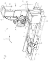
- the adjusting device 4 has an L-shaped support arm 14 which accommodates a pipetting unit 2.
- the pipetting unit is designed as a multi-channel pipette and, in the embodiment shown, is suitable for receiving a total of 12 pipette tips 3 .
- the adjusting device 4 has a tower-like guide arm 17 which has guide slots 18 , 19 .
- the carrier arm 14 can be raised or lowered in these guide slots with respect to the sample containers, which are not shown.
- the guide slots 18, 19 of the adjusting device 4 in connection with the support arm 14 create a freedom of movement that runs parallel to the Z-axis.
- the adjusting device 4 is in an in figure 1 led not visible recess.
- the adjusting device consequently enables, with a drive unit preferably installed in the guide arm 14 (not shown in the figures), that the pipetting unit 2 can be raised or lowered and that it can be moved back and forth.
- a relative change in position of the pipetting unit 2 in relation to the containers (not shown) and a waste box 11 is possible.
- a user interface 13 which is arranged in the area of the front side of the base plate 5, it is possible to program a pipetting process with a large number of work cycles.
- this programming on the control panel 20, which is located on the handle 21 of the pipetting unit 2.
- the base plate 5 also forms the basis for receiving the different containers.
- the containers as such are not shown, but the shelves 7, 8, 9 and 10 can be seen.
- the containers required for an examination are placed there.
- the parking spaces 8, 9 and 10 are provided for receptacles or target containers for samples or liquids, and the parking space 7 is generally used for storage containers for pipette tips.
- unused pipette tips 3 can be automatically picked up by the pipette unit 2 in a known manner.
- the pipetting unit 2 is placed using the positioning device 4 over the parking space 7 or over the reservoir for pipette tips, not shown, and lowered as a result until the free ends of the pipette tips 3 with the Connecting portion 22 of the pipetting unit are engaged.
- the pipette tips 3 are thus connected to the pipetting unit 2 via the connecting section 22 and can be used for taking up a sample or liquid from a receiving container and for the subsequent distribution of the sample or liquid in target containers.
- the adjusting device 4 moves the pipetting unit over the waste box 11.
- the contaminated pipette tips 3 are stripped off the connecting section 22 by means of a mechanism (not shown) and the stripped pipette tips fall into the waste box.
- This process is monitored with a sensor unit 12 .
- This sensor unit 12 is located in a mast-like support arm 6 and is pivotably mounted there. The pivoting movement is aligned in such a way that the detection area of the sensor unit 12, which is formed by a light beam 15, is pivoted in the plane spanned by the X-axis and the Y-axis.
- the pivoting range is approximately +/- 40° in relation to the center position of the sensor unit 12. In this center position of the sensor unit 12, the detection area is aligned parallel to the X-axis. So it's over immediately figure 2 recognizable that when the sensor unit 12 is pivoted from a starting position, which is at -40°, to an end position at +40°, all pipette tips 3 are swept over.
- a reflector element 16 is arranged behind the pipette tips at the opening edge 23 of the waste box 11, which reflects the light beam 15 of the sensor unit 12 and throws it back to a receiver located in the sensor unit. If there is a pipette tip 3 in the light path of the light beam 15, the light beam 15 cannot impinge on the reflector element 16, it is not reflected and the receiver registers the absence or the interruption of the light beam 15 closed the presence of a pipette tip. If a counter that records these interruptions is activated together with the process of pivoting the sensor unit, the number of pipette tips present can be deduced after the pivoting movement has ended.
- Is specified when programming the pipetting process how high the number of used Is pipette tips 3, which can be picked up by the pipetting unit 2, it can be determined by comparing the detected number with the stored number, whether there is an error or not.
- the pipette unit itself can provide information about how many pipette channels it has. In this case, the number of available pipette channels corresponds to the number of pipette tips 3 used.
- the sensor unit 12 with the mast-like support element 6 can also be placed on the narrow side of the waste box. Accordingly, a reflector element 16 is then attached to the opposite narrow side of the waste box.
- pivoting the sensor unit 12 then makes little sense because the individual pipette tips more or less overlap one another from the point of view of the sensor unit and therefore cannot be clearly detected.
- the exit direction of the light beam 15, or to put it another way, that the main direction of the detection area is aligned in such a way that this exit direction assumes an acute angle with the X-axis.
- the light beam runs across or almost diagonally across the opening of the waste box.
- the pipette unit In order to be able to detect the individual pipette tips, the pipette unit must be moved in the X direction. As a result, one pipette tip 3 after the other overlaps the detection area and can be detected sequentially. This alternative is not shown in the figures.
- a further alternative embodiment, not shown, can be chosen for the mast-like support element 6 .
- the carrier element 6 is designed to be adjustable in height in order to be able to adapt the detection range of the sensor unit directly to the height of the containers.
- a pipetting unit 2 in the form of a pipetting module, which is connected to the support arm 14 via a detachable locking system. This makes it possible to remove the pipetting unit 2 from the sample distribution system 1 and use it as a hand-operated pipette.
- the idea according to the invention can also be used in sample distribution systems in which a pipetting unit is permanently is connected to the support arm or in which the pipetting unit is structurally combined with the support arm.
Landscapes
- Chemical & Material Sciences (AREA)
- Health & Medical Sciences (AREA)
- Biochemistry (AREA)
- Physics & Mathematics (AREA)
- Life Sciences & Earth Sciences (AREA)
- Analytical Chemistry (AREA)
- General Health & Medical Sciences (AREA)
- General Physics & Mathematics (AREA)
- Immunology (AREA)
- Pathology (AREA)
- Chemical Kinetics & Catalysis (AREA)
- Clinical Laboratory Science (AREA)
- Engineering & Computer Science (AREA)
- Human Computer Interaction (AREA)
- Automatic Analysis And Handling Materials Therefor (AREA)
Claims (15)
- Système de distribution d'échantillons (1)avec un dispositif de réglage (4) pour recevoir une unité de pipetage (2) avec au moins un embout de pipette interchangeable (3), le dispositif de réglage (4) étant approprié pour changer le positionnement de l'embout de pipette (2) par rapport à une plaque de base (5) etavec une unité de détecteur (12) qui est formée pour détecter l'existence ou le manque d'embouts de pipettes (3),l'unité de détecteur (12) étant réalisé comme une barrière photoélectrique, en particulier comme une barrière photoélectrique à réflexion, et présentant une zone de détection pour balayer les embouts de pipettes (3) etl'unité de détecteur (12) et le dispositif de réglage (4) étant mobiles l'un par rapport à l'autre pour conclure à l'existence d'un embout de pipette (3) lorsque celui-ci se trouve dans la zone de détection de l'unité de capteur (12), caractérisé en ceque l'unité de capteur (12) est appropriée pour balayer tous les embouts de pipettes lors du pivotement de l'unité de capteur (12).
- Système de distribution d'échantillons selon la revendication 1, caractérisé en ce qu'un compteur est associé à l'unité de capteur (12) pour déterminer le nombre des embouts de pipettes (3).
- Système de distribution d'échantillons selon l'une des revendications précédentes, caractérisé en ce que la zone de détection de l'unité de détecteur (12) est formée par un seul faisceau lumineux ou une seule impulsion lumineuse (15).
- Système de distribution d'échantillons selon l'une des revendications précédentes, caractérisé en ce que l'unité de capteur (12) est positionnée pivotante pour pivoter la zone de détection autour de l'axe Z d'une position de départ à une position finale.
- Système de distribution d'échantillons selon l'une des revendications précédentes, caractérisé en ce que l'unité de capteur (12) est montée de telle manière que la direction principale de la zone de détection forme un angle aigu avec la direction de déplacement parallèlement à l'axe X du dispositif de réglage.
- Système de distribution d'échantillons selon l'une des revendications précédentes, caractérisé en ce que l'unité de capteur (12) est placée de telle manière qu'elle met la zone de détection au-dessus des ouvertures des contenants.
- Système de distribution d'échantillons selon l'une des revendications précédentes, caractérisé en ce que l'unité de capteur (12) est reliée à la plaque de base (5) par un élément porteur de type mât (6) et est montée de préférence dans un bras de guidage (17) du dispositif de réglage (4) ou sur un bras de guidage (17) du dispositif de réglage (4).
- Système de distribution d'échantillons selon l'une des revendications précédentes, caractérisé en ce que le dispositif de réglage comprend une unité de pipetage (2) avec au moins un embout de pipette (3) et l'unité de détecteur (12) présente une diode laser pour émettre des impulsions lumineuses ou des faisceaux lumineux (15) et en particulier une optique placée devant la diode laser, l'impulsion lumineuse ou le faisceau lumineux (15) présentant un diamètre de faisceau qui est inférieur à la largeur du plus petit embout de pipette à son endroit le plus étroit et que l'unité de capteur (12) est appropriée pour interagir avec un élément de réflecteur (16) et pour émettre les faisceaux lumineux ou lesi mpulsions lumineuses ( !5) en direction de cet élément de réflecteur (16), l'élément de réflecteur (16) étant placé de préférence sur un bord d'ouverture (23) au moins d'un contenant.
- Système de distribution d'échantillons selon l'une des revendications précédentes, caractérisé en ce que le dispositif de réglage comprend une unité de pipetage (2) avec au moins un embout de pipette (3) et qu'une unité d'évaluation est associée à l'unité de détecteur (12), unité d'évaluation qui est appropriée pour juger la situation et la position des embouts de pipettes (3) par rapport à l'unité de pipetage (2) ainsi que la forme des embouts de pipettes (3).
- Procédé pour distribuer des échantillons avec un système de distribution d'échantillons selon l'une des revendications précédentes qui comprend les étapes suivantes :a) réception d'embouts de pipettes (3) au moyen d'une unité de pipetage (2),b) exécution d'au moins une opération de pipetage,c) déplacement de l'unité de pipetage (2) vers une zone de détection de l'unité de capteur (12),d) déplacement de l'unité de pipetage (2) par rapport à l'unité de capteur (12) pour vérifier dans une étape de vérification par balayage avec un faisceau lumineux ou une impulsion lumineuse si un embout de pipette (3) se trouve dans la zone de détection de l'unité de capteur (12), l'étape de vérification étant exécutée au moyen de l'unité de capteur (12) qui est réalisée comme une barrière photoélectrique,
l'unité de capteur (12) émettant pendant l'étape de vérification des faisceaux lumineux ou des impulsions lumineuses (15) en direction d'un élément de réflecteur (16) et que les faisceau lumineux ou les impulsions lumineuses (15) sont réfléchies sur l'élément réflecteur (16) pour le cas où il n'existe pas d'embout de pipette (3) dans le parcours lumineux du faisceau lumineux ou de l'impulsion lumineuse (15) et soit redirigée vers l'unité de capteur (12). - Procédé pour distribuer des échantillons selon la revendication 10, caractérisé en ce qu'ila) est vérifié dans une première étape de vérification si tous les embouts de pipettes reçus (3) sont reliés à l'unité de pipetage (2),b) et qu'il est vérifié dans une seconde étape de vérification si tous les embouts de pipettes ont été jetés,c) cependant que les embouts de pipettes (3) sont jetés entre les deux étapes de vérification.
- Procédé pour distribuer des échantillons selon la revendication 11, caractérisé en ce que les étapes de procédé suivantes sont exécutées pendant la première et la seconde étape de vérification :a) réglage d'un compteur à zéro,b) activation de l'unité de capteur (12) et émission d'un faisceau lumineux ou d'une impulsion lumineuse (15), la direction principale de la zone de détection forme un angle aigu avec la direction de déplacement le long de l'axe X de l'unité de pipetage (2),c) déplacement de l'unité de pipetage jusqu'à ce qu'un embout de pipette soit détecté par chevauchement avec la zone de détection et l'interruption du faisceau lumineux ou de l'impulsion lumineuse (15) qui lui est liée,d) augmentation du nombre détecté d'embouts de pipettes dans le compteur d'un,e) répétition des étapes en commençant par b).
- Procédé pour distribuer des échantillons selon la revendication 11, caractérisé en ce que les étapes de procédé suivantes sont exécutées pendant la première ou la seconde étape de vérification :a) mise d'un compteur à zéro et pivotement d'une unité de capteur (12) dans une position de démarrage,b) activation de l'unité de détecteur (12) et émission d'un faisceau lumineux ou d'une impulsion lumineuse (15),c) pivotement du faisceau lumineux ou de l'impulsion lumineuse (15) jusqu'à ce qu'un embout de pipette soit détecté par chevauchement avec la zone de détection et l'interruption du faisceau lumineux ou de l'impulsion lumineuse (15) qui lui est liée,d) augmentation du nombre détecté d'embouts de pipettes dans le compteur d'un,e) répétition des étapes en commençant par b) jusqu'à ce qu'une position finale soit atteinte.
- Procédé pour distribuer des échantillons selon l'une des revendications 12 ou 13, caractérisé en ce que les étapes de procédé b) et c) sont exécutées pour détecter une séquence de signaux d'endroits clairs et foncés et que cette séquence de signaux est évaluée pour déterminer le nombre d'embouts de pipettes à partir du nombre d'endroits foncés.
- Procédé pour distribuer des échantillons selon l'une des revendications 11, 12, 13 ou 14, caractérisé en ce que les étapes de procédé suivantes sont exécutées pendant la première ou la seconde étape de vérification :a) lecture du nombre d'embouts de pipettes détecté par le compteur,b) comparaison du nombre d'embouts de pipettes détecté avec le nombre d'embouts de pipettes (3) mis en opération,c) démarrage d'un nouveau cycle de pipetage lors de la coïncidence de la valeur du compteur avec le nombre d'embouts de pipettes,d) émission d'un message d'erreur si la valeur du compteur ne coïncide pas avec le nombre d'embouts de pipettes.
Applications Claiming Priority (1)
| Application Number | Priority Date | Filing Date | Title |
|---|---|---|---|
| CH01583/17A CH714486A1 (de) | 2017-12-21 | 2017-12-21 | Probenverteilsystem und Verfahren zum Verteilen von Proben. |
Publications (2)
| Publication Number | Publication Date |
|---|---|
| EP3501655A1 EP3501655A1 (fr) | 2019-06-26 |
| EP3501655B1 true EP3501655B1 (fr) | 2022-05-18 |
Family
ID=62683071
Family Applications (1)
| Application Number | Title | Priority Date | Filing Date |
|---|---|---|---|
| EP18215662.0A Active EP3501655B1 (fr) | 2017-12-21 | 2018-12-21 | Système de distribution d'échantillons et procédé de distribution d'échantillons |
Country Status (3)
| Country | Link |
|---|---|
| US (1) | US11073530B2 (fr) |
| EP (1) | EP3501655B1 (fr) |
| CH (1) | CH714486A1 (fr) |
Families Citing this family (4)
| Publication number | Priority date | Publication date | Assignee | Title |
|---|---|---|---|---|
| WO2019166512A1 (fr) * | 2018-02-27 | 2019-09-06 | Eppendorf Ag | Appareil de mesure pour une machine automatique de laboratoire, destiné à mesurer un objet, objet pour ledit appareil de mesure et procédé de mesure |
| CN111167532A (zh) * | 2020-01-10 | 2020-05-19 | 济南翼菲自动化科技有限公司 | 一种用于生物试验移液的自动化设备 |
| DE102021204570A1 (de) | 2021-05-06 | 2022-11-10 | Fraunhofer-Gesellschaft zur Förderung der angewandten Forschung eingetragener Verein | Dosierkopf und Fluidiksystem zur Aufnahme und Dosierung wenigstens eines Mediums |
| CN114460320B (zh) * | 2022-04-14 | 2022-06-21 | 深圳市帝迈生物技术有限公司 | 样本分析仪及其样本检测流程 |
Family Cites Families (33)
| Publication number | Priority date | Publication date | Assignee | Title |
|---|---|---|---|---|
| US3588480A (en) | 1968-12-06 | 1971-06-28 | Fairbanks Morse Inc | Processing control system |
| US4478094A (en) * | 1983-01-21 | 1984-10-23 | Cetus Corporation | Liquid sample handling system |
| US4616514A (en) | 1983-06-06 | 1986-10-14 | Rainin Instrument Co., Inc. | Replaceable tip assembly for pipette |
| GB2147996A (en) | 1983-10-12 | 1985-05-22 | Sundberg Carl Axel | Electrical measurement of the dimensions or volumes of articles |
| FI87740C (fi) | 1990-05-04 | 1994-04-08 | Biohit Oy | Pipett |
| US5141871A (en) * | 1990-05-10 | 1992-08-25 | Pb Diagnostic Systems, Inc. | Fluid dispensing system with optical locator |
| US5290521A (en) | 1992-09-04 | 1994-03-01 | Destefano Jr Albert M | Lab-top work station |
| US6090348A (en) | 1997-03-14 | 2000-07-18 | Becton, Dickinson And Company | Method for programming an electronic pipetter |
| DE19850841A1 (de) | 1998-11-04 | 2000-05-25 | Eppendorf Geraetebau Netheler | Verfahren zum Betreiben eines elektronischen Dosiersystems und Dosiersystem zur Durchführung des Verfahrens |
| DE10040849A1 (de) * | 2000-08-21 | 2002-03-21 | Mwg Biotech Ag | Pipettierkopf für einen Roboter mit mehreren Pipettierspitzen |
| US7288228B2 (en) | 2002-02-12 | 2007-10-30 | Gilson, Inc. | Sample injection system |
| US7976793B2 (en) | 2003-11-27 | 2011-07-12 | Gilson S.A.S. | Electronic pipette |
| DE102004003434B4 (de) | 2004-01-21 | 2006-06-08 | Eppendorf Ag | Pipettiervorrichtung mit einer Verdrängungseinrichtung und einer damit lösbar verbundenen Antriebseinrichtung |
| US7618589B2 (en) * | 2004-09-07 | 2009-11-17 | Hitachi Koki Co., Ltd. | Automatic dispenser |
| WO2008027569A2 (fr) | 2006-09-01 | 2008-03-06 | Agr International, Inc. | Système d'inspection en ligne pour profiler verticalement des contenants en matière plastique à l'aide de sources de lumière à spectres discrets à multiples longueurs d'onde |
| US7662344B2 (en) | 2006-10-24 | 2010-02-16 | Viaflo Corporation | Locking pipette tip and mounting shaft |
| DE102008010267A1 (de) | 2008-02-19 | 2009-08-20 | Nyársik, Lajos, Dr. | Pipettiervorrichtung für manuelle Flüssigkeitshandhabung |
| US8029742B2 (en) | 2008-05-05 | 2011-10-04 | Integra Biosciences Corp. | Multi-channel pipettor with repositionable tips |
| US8743368B2 (en) * | 2009-11-12 | 2014-06-03 | General Electric Company | Optical sensor system and method of sensing |
| JP2011115759A (ja) | 2009-12-07 | 2011-06-16 | Fukae Kasei Kk | ピペット装置 |
| DE102010005722A1 (de) | 2010-01-26 | 2011-07-28 | Eppendorf AG, 22339 | Positioniereinrichtung für eine Probenverteilervorrichtung, Probenverteilervorrichtung mit Positioniereinrichtung und Verfahren zum Positionieren |
| US8372356B2 (en) | 2010-05-03 | 2013-02-12 | Integra Biosciences Corp. | Manually directed, multi-channel electronic pipetting system |
| EP2566619B1 (fr) | 2010-05-03 | 2015-04-15 | Integra Biosciences AG | Régulateur de mouvement involontaire pour pipeteur multi-canaux électronique aux controle manuelle |
| KR101944347B1 (ko) | 2010-11-23 | 2019-04-17 | 앤드류 알리안스 에스. 에이. | 피펫의 프로그래밍 가능한 조작을 위한 장치 및 방법 |
| RU2622432C2 (ru) * | 2011-09-30 | 2017-06-15 | Бектон, Дикинсон Энд Компани | Унифицированная полоска для реактивов |
| EP2698202A3 (fr) | 2012-08-15 | 2017-07-19 | Integra Biosciences AG | Sample distribution system and process |
| PL2735369T3 (pl) | 2012-11-23 | 2017-09-29 | Eppendorf Ag | Pipeta wielokanałowa |
| US9815053B2 (en) | 2013-01-15 | 2017-11-14 | Mettler-Toledo Rainin, LLC | Liquid end assembly for a multichannel air displacement pipette |
| US9555407B2 (en) * | 2013-03-14 | 2017-01-31 | Protedyne Corporation | Laser triangulation for pipette tip position |
| EP2884285B1 (fr) * | 2013-12-13 | 2024-07-24 | F. Hoffmann-La Roche AG | Module d'alimentation pour analyseur automatisé |
| AU2016248939B2 (en) | 2015-04-16 | 2018-03-29 | Integra Biosciences Ag | Volume adjustment for manual pipettor |
| WO2017116960A2 (fr) * | 2015-12-30 | 2017-07-06 | Theranos, Inc. | Pointe de transfert de fluide à pièces multiples |
| CH712010B1 (de) | 2016-01-11 | 2021-10-15 | Integra Biosciences Ag | Pipette mit Abwurfmechanismus für Pipettenspitzen. |
-
2017
- 2017-12-21 CH CH01583/17A patent/CH714486A1/de unknown
-
2018
- 2018-12-19 US US16/225,232 patent/US11073530B2/en active Active
- 2018-12-21 EP EP18215662.0A patent/EP3501655B1/fr active Active
Also Published As
| Publication number | Publication date |
|---|---|
| EP3501655A1 (fr) | 2019-06-26 |
| CH714486A1 (de) | 2019-06-28 |
| US20190195906A1 (en) | 2019-06-27 |
| US11073530B2 (en) | 2021-07-27 |
Similar Documents
| Publication | Publication Date | Title |
|---|---|---|
| EP3501655B1 (fr) | Système de distribution d'échantillons et procédé de distribution d'échantillons | |
| DE69835691T2 (de) | Vielkanal-pipettiergerät | |
| EP1726923B1 (fr) | Procédé et dispositif de mesure de remplissage | |
| EP3795254B1 (fr) | Ensemble piston-cylindre interchangeable pour un distributeur | |
| DE3717907A1 (de) | Automatische probenabgabevorrichtung fuer automatische chemische analysiergeraete | |
| EP2027926A1 (fr) | Appareil de fonctionnement de matériel biologique | |
| EP0691158A2 (fr) | Système de pipetage | |
| EP0301390A2 (fr) | Palpeur pour des appareils de mesure de coordonnées | |
| EP1489425B1 (fr) | Dispositif et méthode pour positionner des éléments fonctionnels et/ou des récipients sur la surface de travail d'un manipulateur de laboratoire à l'aide de deux barrières optiques se croisant | |
| EP3554707B1 (fr) | Fixation et séparation d'un ensemble piston-cylindre sur/d'un dispositif servant à aspirer et à expulser des volumes de fluide | |
| EP3403725A1 (fr) | Système d'aide au pipetage | |
| EP2350676B1 (fr) | Dispositif d'analyse automatisé présentant un dispositif automatique de prélèvement par pipette et un bras de prélèvement par pipette muni d'un détecteur d'impact | |
| EP3972736A1 (fr) | Ensemble de tamisage de liquide avec déclenchement mécanique de très petites quantités de liquide | |
| DE4405661C2 (de) | Verfahren und Vorrichtung zum mechanischen Fügen von nichtmetallischen Werkstücken | |
| EP2620775A1 (fr) | Cartouche d'enregistrement | |
| DE19914962A1 (de) | Optoelektronische Vorrichtung | |
| EP3489693B1 (fr) | Procédé de commande d'un dispositif de pipetage | |
| DE3340084C2 (de) | Vorrichtung zur Positionierung von Bauteilen auf einem Werkstück | |
| WO2017001676A1 (fr) | Système de pipetage muni d'un dispositif de traitement d'images | |
| EP1745861A1 (fr) | Appareil de mésurer et de trier | |
| EP3971131A2 (fr) | Distributeur de boissons | |
| DE102018131088A1 (de) | Flüssigkeitsdosiervorrichtung zur ballistischen Abgabe von Dosiermengen im Nanoliterbereich, Flüssigkeitsdosierverfahren und Pipettierspitze hierfür | |
| DE102020211533B3 (de) | Messinstrument für ein Laserwerkzeug, Laserwerkzeug und Werkstückbearbeitungsvorrichtung sowie Verfahren zum Messen eines Abstands | |
| DE19956178C2 (de) | Verfahren und Anordnung zur Dokumentierung und/oder Qualitätsicherung beim manuellen Handling von Stoffen | |
| DE3342504A1 (de) | Pipettiervorrichtung |
Legal Events
| Date | Code | Title | Description |
|---|---|---|---|
| PUAI | Public reference made under article 153(3) epc to a published international application that has entered the european phase |
Free format text: ORIGINAL CODE: 0009012 |
|
| STAA | Information on the status of an ep patent application or granted ep patent |
Free format text: STATUS: THE APPLICATION HAS BEEN PUBLISHED |
|
| AK | Designated contracting states |
Kind code of ref document: A1 Designated state(s): AL AT BE BG CH CY CZ DE DK EE ES FI FR GB GR HR HU IE IS IT LI LT LU LV MC MK MT NL NO PL PT RO RS SE SI SK SM TR |
|
| AX | Request for extension of the european patent |
Extension state: BA ME |
|
| STAA | Information on the status of an ep patent application or granted ep patent |
Free format text: STATUS: REQUEST FOR EXAMINATION WAS MADE |
|
| 17P | Request for examination filed |
Effective date: 20191213 |
|
| RBV | Designated contracting states (corrected) |
Designated state(s): AL AT BE BG CH CY CZ DE DK EE ES FI FR GB GR HR HU IE IS IT LI LT LU LV MC MK MT NL NO PL PT RO RS SE SI SK SM TR |
|
| STAA | Information on the status of an ep patent application or granted ep patent |
Free format text: STATUS: EXAMINATION IS IN PROGRESS |
|
| 17Q | First examination report despatched |
Effective date: 20210224 |
|
| GRAP | Despatch of communication of intention to grant a patent |
Free format text: ORIGINAL CODE: EPIDOSNIGR1 |
|
| STAA | Information on the status of an ep patent application or granted ep patent |
Free format text: STATUS: GRANT OF PATENT IS INTENDED |
|
| INTG | Intention to grant announced |
Effective date: 20210714 |
|
| GRAJ | Information related to disapproval of communication of intention to grant by the applicant or resumption of examination proceedings by the epo deleted |
Free format text: ORIGINAL CODE: EPIDOSDIGR1 |
|
| STAA | Information on the status of an ep patent application or granted ep patent |
Free format text: STATUS: EXAMINATION IS IN PROGRESS |
|
| INTC | Intention to grant announced (deleted) | ||
| GRAP | Despatch of communication of intention to grant a patent |
Free format text: ORIGINAL CODE: EPIDOSNIGR1 |
|
| STAA | Information on the status of an ep patent application or granted ep patent |
Free format text: STATUS: GRANT OF PATENT IS INTENDED |
|
| INTG | Intention to grant announced |
Effective date: 20211208 |
|
| GRAS | Grant fee paid |
Free format text: ORIGINAL CODE: EPIDOSNIGR3 |
|
| GRAA | (expected) grant |
Free format text: ORIGINAL CODE: 0009210 |
|
| STAA | Information on the status of an ep patent application or granted ep patent |
Free format text: STATUS: THE PATENT HAS BEEN GRANTED |
|
| AK | Designated contracting states |
Kind code of ref document: B1 Designated state(s): AL AT BE BG CH CY CZ DE DK EE ES FI FR GB GR HR HU IE IS IT LI LT LU LV MC MK MT NL NO PL PT RO RS SE SI SK SM TR |
|
| REG | Reference to a national code |
Ref country code: GB Ref legal event code: FG4D Free format text: NOT ENGLISH |
|
| REG | Reference to a national code |
Ref country code: CH Ref legal event code: EP |
|
| REG | Reference to a national code |
Ref country code: IE Ref legal event code: FG4D Free format text: LANGUAGE OF EP DOCUMENT: GERMAN |
|
| REG | Reference to a national code |
Ref country code: AT Ref legal event code: REF Ref document number: 1492842 Country of ref document: AT Kind code of ref document: T Effective date: 20220615 Ref country code: DE Ref legal event code: R096 Ref document number: 502018009702 Country of ref document: DE |
|
| REG | Reference to a national code |
Ref country code: LT Ref legal event code: MG9D |
|
| REG | Reference to a national code |
Ref country code: NL Ref legal event code: MP Effective date: 20220518 |
|
| PG25 | Lapsed in a contracting state [announced via postgrant information from national office to epo] |
Ref country code: SE Free format text: LAPSE BECAUSE OF FAILURE TO SUBMIT A TRANSLATION OF THE DESCRIPTION OR TO PAY THE FEE WITHIN THE PRESCRIBED TIME-LIMIT Effective date: 20220518 Ref country code: PT Free format text: LAPSE BECAUSE OF FAILURE TO SUBMIT A TRANSLATION OF THE DESCRIPTION OR TO PAY THE FEE WITHIN THE PRESCRIBED TIME-LIMIT Effective date: 20220919 Ref country code: NO Free format text: LAPSE BECAUSE OF FAILURE TO SUBMIT A TRANSLATION OF THE DESCRIPTION OR TO PAY THE FEE WITHIN THE PRESCRIBED TIME-LIMIT Effective date: 20220818 Ref country code: NL Free format text: LAPSE BECAUSE OF FAILURE TO SUBMIT A TRANSLATION OF THE DESCRIPTION OR TO PAY THE FEE WITHIN THE PRESCRIBED TIME-LIMIT Effective date: 20220518 Ref country code: LT Free format text: LAPSE BECAUSE OF FAILURE TO SUBMIT A TRANSLATION OF THE DESCRIPTION OR TO PAY THE FEE WITHIN THE PRESCRIBED TIME-LIMIT Effective date: 20220518 Ref country code: HR Free format text: LAPSE BECAUSE OF FAILURE TO SUBMIT A TRANSLATION OF THE DESCRIPTION OR TO PAY THE FEE WITHIN THE PRESCRIBED TIME-LIMIT Effective date: 20220518 Ref country code: GR Free format text: LAPSE BECAUSE OF FAILURE TO SUBMIT A TRANSLATION OF THE DESCRIPTION OR TO PAY THE FEE WITHIN THE PRESCRIBED TIME-LIMIT Effective date: 20220819 Ref country code: FI Free format text: LAPSE BECAUSE OF FAILURE TO SUBMIT A TRANSLATION OF THE DESCRIPTION OR TO PAY THE FEE WITHIN THE PRESCRIBED TIME-LIMIT Effective date: 20220518 Ref country code: ES Free format text: LAPSE BECAUSE OF FAILURE TO SUBMIT A TRANSLATION OF THE DESCRIPTION OR TO PAY THE FEE WITHIN THE PRESCRIBED TIME-LIMIT Effective date: 20220518 Ref country code: BG Free format text: LAPSE BECAUSE OF FAILURE TO SUBMIT A TRANSLATION OF THE DESCRIPTION OR TO PAY THE FEE WITHIN THE PRESCRIBED TIME-LIMIT Effective date: 20220818 |
|
| PG25 | Lapsed in a contracting state [announced via postgrant information from national office to epo] |
Ref country code: RS Free format text: LAPSE BECAUSE OF FAILURE TO SUBMIT A TRANSLATION OF THE DESCRIPTION OR TO PAY THE FEE WITHIN THE PRESCRIBED TIME-LIMIT Effective date: 20220518 Ref country code: PL Free format text: LAPSE BECAUSE OF FAILURE TO SUBMIT A TRANSLATION OF THE DESCRIPTION OR TO PAY THE FEE WITHIN THE PRESCRIBED TIME-LIMIT Effective date: 20220518 Ref country code: LV Free format text: LAPSE BECAUSE OF FAILURE TO SUBMIT A TRANSLATION OF THE DESCRIPTION OR TO PAY THE FEE WITHIN THE PRESCRIBED TIME-LIMIT Effective date: 20220518 Ref country code: IS Free format text: LAPSE BECAUSE OF FAILURE TO SUBMIT A TRANSLATION OF THE DESCRIPTION OR TO PAY THE FEE WITHIN THE PRESCRIBED TIME-LIMIT Effective date: 20220918 |
|
| PG25 | Lapsed in a contracting state [announced via postgrant information from national office to epo] |
Ref country code: SM Free format text: LAPSE BECAUSE OF FAILURE TO SUBMIT A TRANSLATION OF THE DESCRIPTION OR TO PAY THE FEE WITHIN THE PRESCRIBED TIME-LIMIT Effective date: 20220518 Ref country code: SK Free format text: LAPSE BECAUSE OF FAILURE TO SUBMIT A TRANSLATION OF THE DESCRIPTION OR TO PAY THE FEE WITHIN THE PRESCRIBED TIME-LIMIT Effective date: 20220518 Ref country code: RO Free format text: LAPSE BECAUSE OF FAILURE TO SUBMIT A TRANSLATION OF THE DESCRIPTION OR TO PAY THE FEE WITHIN THE PRESCRIBED TIME-LIMIT Effective date: 20220518 Ref country code: EE Free format text: LAPSE BECAUSE OF FAILURE TO SUBMIT A TRANSLATION OF THE DESCRIPTION OR TO PAY THE FEE WITHIN THE PRESCRIBED TIME-LIMIT Effective date: 20220518 Ref country code: DK Free format text: LAPSE BECAUSE OF FAILURE TO SUBMIT A TRANSLATION OF THE DESCRIPTION OR TO PAY THE FEE WITHIN THE PRESCRIBED TIME-LIMIT Effective date: 20220518 Ref country code: CZ Free format text: LAPSE BECAUSE OF FAILURE TO SUBMIT A TRANSLATION OF THE DESCRIPTION OR TO PAY THE FEE WITHIN THE PRESCRIBED TIME-LIMIT Effective date: 20220518 |
|
| REG | Reference to a national code |
Ref country code: DE Ref legal event code: R097 Ref document number: 502018009702 Country of ref document: DE |
|
| PLBE | No opposition filed within time limit |
Free format text: ORIGINAL CODE: 0009261 |
|
| STAA | Information on the status of an ep patent application or granted ep patent |
Free format text: STATUS: NO OPPOSITION FILED WITHIN TIME LIMIT |
|
| PG25 | Lapsed in a contracting state [announced via postgrant information from national office to epo] |
Ref country code: AL Free format text: LAPSE BECAUSE OF FAILURE TO SUBMIT A TRANSLATION OF THE DESCRIPTION OR TO PAY THE FEE WITHIN THE PRESCRIBED TIME-LIMIT Effective date: 20220518 |
|
| 26N | No opposition filed |
Effective date: 20230221 |
|
| PG25 | Lapsed in a contracting state [announced via postgrant information from national office to epo] |
Ref country code: SI Free format text: LAPSE BECAUSE OF FAILURE TO SUBMIT A TRANSLATION OF THE DESCRIPTION OR TO PAY THE FEE WITHIN THE PRESCRIBED TIME-LIMIT Effective date: 20220518 |
|
| REG | Reference to a national code |
Ref country code: BE Ref legal event code: MM Effective date: 20221231 |
|
| PG25 | Lapsed in a contracting state [announced via postgrant information from national office to epo] |
Ref country code: LU Free format text: LAPSE BECAUSE OF NON-PAYMENT OF DUE FEES Effective date: 20221221 |
|
| PG25 | Lapsed in a contracting state [announced via postgrant information from national office to epo] |
Ref country code: IE Free format text: LAPSE BECAUSE OF NON-PAYMENT OF DUE FEES Effective date: 20221221 |
|
| PG25 | Lapsed in a contracting state [announced via postgrant information from national office to epo] |
Ref country code: FR Free format text: LAPSE BECAUSE OF NON-PAYMENT OF DUE FEES Effective date: 20221231 Ref country code: BE Free format text: LAPSE BECAUSE OF NON-PAYMENT OF DUE FEES Effective date: 20221231 |
|
| PGFP | Annual fee paid to national office [announced via postgrant information from national office to epo] |
Ref country code: GB Payment date: 20231220 Year of fee payment: 6 |
|
| PG25 | Lapsed in a contracting state [announced via postgrant information from national office to epo] |
Ref country code: IT Free format text: LAPSE BECAUSE OF FAILURE TO SUBMIT A TRANSLATION OF THE DESCRIPTION OR TO PAY THE FEE WITHIN THE PRESCRIBED TIME-LIMIT Effective date: 20220518 |
|
| PGFP | Annual fee paid to national office [announced via postgrant information from national office to epo] |
Ref country code: DE Payment date: 20231214 Year of fee payment: 6 |
|
| REG | Reference to a national code |
Ref country code: CH Ref legal event code: PK Free format text: BERICHTIGUNGEN |
|
| PG25 | Lapsed in a contracting state [announced via postgrant information from national office to epo] |
Ref country code: HU Free format text: LAPSE BECAUSE OF FAILURE TO SUBMIT A TRANSLATION OF THE DESCRIPTION OR TO PAY THE FEE WITHIN THE PRESCRIBED TIME-LIMIT; INVALID AB INITIO Effective date: 20181221 |
|
| PG25 | Lapsed in a contracting state [announced via postgrant information from national office to epo] |
Ref country code: CY Free format text: LAPSE BECAUSE OF FAILURE TO SUBMIT A TRANSLATION OF THE DESCRIPTION OR TO PAY THE FEE WITHIN THE PRESCRIBED TIME-LIMIT Effective date: 20220511 |
|
| PGFP | Annual fee paid to national office [announced via postgrant information from national office to epo] |
Ref country code: CH Payment date: 20240101 Year of fee payment: 6 |
|
| PG25 | Lapsed in a contracting state [announced via postgrant information from national office to epo] |
Ref country code: MK Free format text: LAPSE BECAUSE OF FAILURE TO SUBMIT A TRANSLATION OF THE DESCRIPTION OR TO PAY THE FEE WITHIN THE PRESCRIBED TIME-LIMIT Effective date: 20220511 |
|
| PG25 | Lapsed in a contracting state [announced via postgrant information from national office to epo] |
Ref country code: MC Free format text: LAPSE BECAUSE OF FAILURE TO SUBMIT A TRANSLATION OF THE DESCRIPTION OR TO PAY THE FEE WITHIN THE PRESCRIBED TIME-LIMIT Effective date: 20220518 |
|
| PG25 | Lapsed in a contracting state [announced via postgrant information from national office to epo] |
Ref country code: MC Free format text: LAPSE BECAUSE OF FAILURE TO SUBMIT A TRANSLATION OF THE DESCRIPTION OR TO PAY THE FEE WITHIN THE PRESCRIBED TIME-LIMIT Effective date: 20220518 |
|
| PG25 | Lapsed in a contracting state [announced via postgrant information from national office to epo] |
Ref country code: MT Free format text: LAPSE BECAUSE OF FAILURE TO SUBMIT A TRANSLATION OF THE DESCRIPTION OR TO PAY THE FEE WITHIN THE PRESCRIBED TIME-LIMIT Effective date: 20220511 |